US809339A - Fluid-sealing device for gas-producers. - Google Patents
Fluid-sealing device for gas-producers. Download PDFInfo
- Publication number
- US809339A US809339A US27463905A US1905274639A US809339A US 809339 A US809339 A US 809339A US 27463905 A US27463905 A US 27463905A US 1905274639 A US1905274639 A US 1905274639A US 809339 A US809339 A US 809339A
- Authority
- US
- United States
- Prior art keywords
- gas
- fluid
- sealing device
- water
- chamber
- Prior art date
- Legal status (The legal status is an assumption and is not a legal conclusion. Google has not performed a legal analysis and makes no representation as to the accuracy of the status listed.)
- Expired - Lifetime
Links
Images
Classifications
-
- C—CHEMISTRY; METALLURGY
- C09—DYES; PAINTS; POLISHES; NATURAL RESINS; ADHESIVES; COMPOSITIONS NOT OTHERWISE PROVIDED FOR; APPLICATIONS OF MATERIALS NOT OTHERWISE PROVIDED FOR
- C09K—MATERIALS FOR MISCELLANEOUS APPLICATIONS, NOT PROVIDED FOR ELSEWHERE
- C09K3/00—Materials not provided for elsewhere
Definitions
- WITNESSES INVENTOR. Qwm Z49 %/1/L. Ctbkm dafila UNITED STATES PATENT OFFICE.
- This invention relates to fluid-sealing devices operating by displacement; and the object of the invention is to produce a threeway valve for power gas-producers which automatically creates avent for the producergas into a chimney or elsewhere when the flow of gas to the engine is stopped.
- the invention consists of two or more chambers arranged to form water seals to their inlets and outlets by the movement of a plunger or plungers contained therein which displaces the water in said chambers.
- F and F are two cylindrical chambers having outlet and inlet pipes, as shown. These chambers are provided with movable displacement-plungers D and D, held in position by means of s rings or other devices.
- S and S are st g-boXes through which the piston-rods pass.
- H and H are the operating-handles for same.
- a and C are outlet-pipes, and B is the inlet, while the pipe G connects the two cylinders, as shown.
- A may be connected to a stack, while 0 may be connected to a gas-enine.
- the plunger D is preferably constructed to work loosely in the chamber F in order that any tarry matter deposited by the gas entering at B may not prevent the free operation of said plunger.
- My invention provides a hitherto unknown means for automatically ventin the producer when the gas-flow is cut ofl at the engine, and thus certainly prevents the troublesome explosions, of frequent occurrence in the past, through failure on the part of the operator to properly vent the producer after shutting oif the gas at the engine.
- a fluid-sealing device for gases comprising two chambers adapted to contain wa ter; means for connecting the two chambers; means for raising and lowering the waterlevel in each chamber by displacement; and ports in said chambers aflording inlet and outlet passages for the gas.
- fluid-sealing device consisting of two connecting-chambers having ports opening thereinto, and having displacement-plungers adapted to close one or more ports solely by the water-sealing thereof.
- a fluid -sealing device comprising the chambers F and F having the gas-inlet B and the gas-outlets A and C; displacement-plungers D and D and connecting-passage G.
- a fluid sealing device comprising a chamber having a as-inlet and two gas-outlets one or other 0 said outlets being at all times sealed by a water seal; a second chamber having connection with the first chamber through one of said outlets; means for simultaneously opening one of said outlets and closing the other of said outlets by water displacement.
- a fluid-sealing device comprising two 5 chambers adapted to contain water; in the upper part of one chamber a gas-inlet in the lower part a gas-outlet and midway said inlet and outlet a second outlet connecting with the remaining chamber in its lower part;
Landscapes
- Chemical & Material Sciences (AREA)
- Engineering & Computer Science (AREA)
- Materials Engineering (AREA)
- Organic Chemistry (AREA)
- Multiple-Way Valves (AREA)
Description
No. 809,389. PATBNTED JAN. 9, 1906.
G. M. S. TAIT. FLUID SEALING DEVICE FOR GAS PRODUCERS.
APPLICATION FILED AUG. 17, 1905.
WITNESSES: INVENTOR. Qwm Z49 %/1/L. Ctbkm dafila UNITED STATES PATENT OFFICE.
GODFREY M. S. TAIT, MONTCLAIR, NEW JERSEY, ASSIGNOR TO COMBUSTION UTILITIES COMPANY, OF NEW YORK, N. Y., A COR- PORATION OF NEW YORK.
Specification of Letters Patent.
Patented Jan. 9, 1906.
Application filed August 17,1905- Serial No. 274,639.
To all whom it may concern.-
Be it known that I, GODFREY M. S. TAIT, a subject of the King of Great Britain, and a resident of Montclair, in the county of Essex and State of New Jersey, have invented certain new and useful Improvements in Fluid- Sealing Devices for Gas-Producers, of which the following is a specification.
This invention relates to fluid-sealing devices operating by displacement; and the object of the invention is to produce a threeway valve for power gas-producers which automatically creates avent for the producergas into a chimney or elsewhere when the flow of gas to the engine is stopped.
The invention consists of two or more chambers arranged to form water seals to their inlets and outlets by the movement of a plunger or plungers contained therein which displaces the water in said chambers.
One form of the device is shown in the illustration herewith; but it is not essential that this invention should consist of two separate cylindrical chambers, as shown, it being equally practical'to build them square or both together in one boX with a division or other similar arrangement.
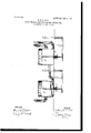
Referring to the illustration herewith, F and F are two cylindrical chambers having outlet and inlet pipes, as shown. These chambers are provided with movable displacement-plungers D and D, held in position by means of s rings or other devices.
S and S are st g-boXes through which the piston-rods pass. H and H are the operating-handles for same.
A and C are outlet-pipes, and B is the inlet, while the pipe G connects the two cylinders, as shown. A may be connected to a stack, while 0 may be connected to a gas-enine.
b The plunger D is preferably constructed to work loosely in the chamber F in order that any tarry matter deposited by the gas entering at B may not prevent the free operation of said plunger.
The operation of the apparatus is as follows; Referrin to the illustration, all ases enter the cham er F through pipe B an will when the apparatus is in the position shown flow out through pipe 0 as pipe G is sealed by the water in chamber F. To change the flow of the gas, it is only necessary to elevate.
the handle H, and the plunger D descends in space F, thereby displacing the water contained in this chamber and causing same to flow out through pipe G into the space F. As soon as the handle is released part D by action of spring or other device resumes its former position, as shown in the illustration. F now contains the water which was in F, with the result that pipe 0 is water-sealed, whereas pipe G is open on account of the removal of Water in chamber F. The flow of the gas is therefore down pipe B, across the surface of the water in chamber F, through pipe G, through chamber F, and out through pipe A to the stack. To reverse this connection, it is only necessary to pull handle H, when part D descends into space F, displacing the water contained therein through ipe G back into space F, as formerly, in w 'ch case the flow of the gas will be, as in the first instance, down pipe B, through space F, and up pipe 0.
My invention provides a hitherto unknown means for automatically ventin the producer when the gas-flow is cut ofl at the engine, and thus certainly prevents the troublesome explosions, of frequent occurrence in the past, through failure on the part of the operator to properly vent the producer after shutting oif the gas at the engine.
What I claim 1s 1. A fluid-sealing device for gases comprising two chambers adapted to contain wa ter; means for connecting the two chambers; means for raising and lowering the waterlevel in each chamber by displacement; and ports in said chambers aflording inlet and outlet passages for the gas.
2. fluid-sealing device consisting of two connecting-chambers having ports opening thereinto, and having displacement-plungers adapted to close one or more ports solely by the water-sealing thereof.
3. A fluid -sealing device, comprising the chambers F and F having the gas-inlet B and the gas-outlets A and C; displacement-plungers D and D and connecting-passage G.
4. A fluid sealing device comprising a chamber having a as-inlet and two gas-outlets one or other 0 said outlets being at all times sealed by a water seal; a second chamber having connection with the first chamber through one of said outlets; means for simultaneously opening one of said outlets and closing the other of said outlets by water displacement.
5. A fluid-sealing device comprising two 5 chambers adapted to contain water; in the upper part of one chamber a gas-inlet in the lower part a gas-outlet and midway said inlet and outlet a second outlet connecting with the remaining chamber in its lower part;
means for alternately water-sealing either of 10 said outlets whereby one outlet is always open whenever the other outlet is closed.
Signed at New York, in the county of New York and State of New York.
GODFREY M. S. TAIT. Witnesses:
OARLETON ELLIs, JAs. K. CLARK.
Priority Applications (1)
| Application Number | Priority Date | Filing Date | Title |
|---|---|---|---|
| US27463905A US809339A (en) | 1905-08-17 | 1905-08-17 | Fluid-sealing device for gas-producers. |
Applications Claiming Priority (1)
| Application Number | Priority Date | Filing Date | Title |
|---|---|---|---|
| US27463905A US809339A (en) | 1905-08-17 | 1905-08-17 | Fluid-sealing device for gas-producers. |
Publications (1)
| Publication Number | Publication Date |
|---|---|
| US809339A true US809339A (en) | 1906-01-09 |
Family
ID=2877820
Family Applications (1)
| Application Number | Title | Priority Date | Filing Date |
|---|---|---|---|
| US27463905A Expired - Lifetime US809339A (en) | 1905-08-17 | 1905-08-17 | Fluid-sealing device for gas-producers. |
Country Status (1)
| Country | Link |
|---|---|
| US (1) | US809339A (en) |
-
1905
- 1905-08-17 US US27463905A patent/US809339A/en not_active Expired - Lifetime
Similar Documents
| Publication | Publication Date | Title |
|---|---|---|
| US809339A (en) | Fluid-sealing device for gas-producers. | |
| US805295A (en) | Apparatus for preventing the escape of gas from gas-generators. | |
| US1001028A (en) | Purge-valve for gas-producer plants. | |
| US825064A (en) | Valve for gas-generators. | |
| US703583A (en) | Device for packing sliding gate-valves. | |
| US1067610A (en) | Automatic back-surge seal for sewerage systems. | |
| US1189566A (en) | Strainer. | |
| US686846A (en) | Liquid-controlled valve. | |
| US606535A (en) | Stop and waste cock | |
| US404392A (en) | Valve | |
| US115334A (en) | Improvement in exhaust apparatus for gas-works | |
| US981708A (en) | Water-gas producer. | |
| US550236A (en) | Apparatus for manufactu re of gas | |
| US687409A (en) | Cut-off valve. | |
| US211590A (en) | Improvement in center-seal purge-valves | |
| US922389A (en) | Water-gas apparatus. | |
| US585592A (en) | Reversing-valve | |
| US948049A (en) | Foul-gas valve. | |
| US561203A (en) | Frederick southwell cripps | |
| US829518A (en) | Apparatus for producing gas. | |
| US1302199A (en) | Construction of gas-generating apparatus. | |
| US934446A (en) | Gas-producer. | |
| US985879A (en) | Balanced valve. | |
| SE409138B (en) | VALVE WITH HALCYLINDRICAL VENTIOR | |
| CA111771A (en) | Water vessel for gas retor furnaces |