US809334A - Disk-sharpener. - Google Patents
Disk-sharpener. Download PDFInfo
- Publication number
- US809334A US809334A US25609805A US1905256098A US809334A US 809334 A US809334 A US 809334A US 25609805 A US25609805 A US 25609805A US 1905256098 A US1905256098 A US 1905256098A US 809334 A US809334 A US 809334A
- Authority
- US
- United States
- Prior art keywords
- disk
- clamp member
- tool
- standard
- cutter
- Prior art date
- Legal status (The legal status is an assumption and is not a legal conclusion. Google has not performed a legal analysis and makes no representation as to the accuracy of the status listed.)
- Expired - Lifetime
Links
- 239000000463 material Substances 0.000 description 3
- 238000010276 construction Methods 0.000 description 2
- 230000000694 effects Effects 0.000 description 2
- 238000005096 rolling process Methods 0.000 description 2
- 239000000853 adhesive Substances 0.000 description 1
- 230000001070 adhesive effect Effects 0.000 description 1
- 230000015572 biosynthetic process Effects 0.000 description 1
- 229910001651 emery Inorganic materials 0.000 description 1
- 239000003292 glue Substances 0.000 description 1
- 210000003141 lower extremity Anatomy 0.000 description 1
- 238000000034 method Methods 0.000 description 1
- NJPPVKZQTLUDBO-UHFFFAOYSA-N novaluron Chemical group C1=C(Cl)C(OC(F)(F)C(OC(F)(F)F)F)=CC=C1NC(=O)NC(=O)C1=C(F)C=CC=C1F NJPPVKZQTLUDBO-UHFFFAOYSA-N 0.000 description 1
- 239000004576 sand Substances 0.000 description 1
Images
Classifications
-
- B—PERFORMING OPERATIONS; TRANSPORTING
- B24—GRINDING; POLISHING
- B24B—MACHINES, DEVICES, OR PROCESSES FOR GRINDING OR POLISHING; DRESSING OR CONDITIONING OF ABRADING SURFACES; FEEDING OF GRINDING, POLISHING, OR LAPPING AGENTS
- B24B3/00—Sharpening cutting edges, e.g. of tools; Accessories therefor, e.g. for holding the tools
- B24B3/36—Sharpening cutting edges, e.g. of tools; Accessories therefor, e.g. for holding the tools of cutting blades
- B24B3/46—Sharpening cutting edges, e.g. of tools; Accessories therefor, e.g. for holding the tools of cutting blades of disc blades
- B24B3/466—Sharpening cutting edges, e.g. of tools; Accessories therefor, e.g. for holding the tools of cutting blades of disc blades of cultivator disc blades
Definitions
- This invention appertains to machines of the type designed most especially for sharpening disks, such as rotary colters and harrow and plow cutters.
- An essential feature of the invention is the provision of means whereby different-sized disks may be firmly and securely clamped, interchangeable clamps being provided for the purpose.
- a further purpose of the invention is to devise a tool-holder of novel formation which may be instantly shifted to adapt the cutter to the disk and which may be instantly moved so as to clear the disk when it may be required to inspect the work or after the sharpening process has been completed.
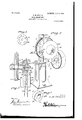
- Figure 1 is a perspective view of a disksharpener constructed in accordance with and embodying the essential features of the invention.
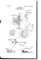
- Fig. 2 is ahorizontal section of the upper portion of the machine, parts being omitted.
- Fig. 3 is a View similar to Fig. 2 of the machine, showing a plow-disk in position to be sharpened.
- Fig. 4 is a perspective view of the series of clamp members or work-holding devices, the parts being arranged in a group.
- Fig. 5 is a detail perspective view of the tool-holder.
- Fig. 6 is an edge view of a disk, showing the relation of the tool and its supporting-standard when applied thereto.
- Fig. 7 is a detail perspective view of the face side of the clamp member or attachment used in connection with a rolling colter or like disk having a hub at its concave side.
- Fig. 8 is a perspective view of the part shown in Fig. 7 as seen from the rear.
- the framework for supporting the operating parts of the machine may be of any desired construction and design and, as illus trated, appears as a stand 1, provided at one side with parallel uprights 2, which are connected at their upper ends.
- the stand 1 is of pedestal form and is provided with bearings in which is journaled the power-driven shaft 4, provided with band-pulley 3 and wormthread 5, in mesh with corresponding cogs 6 ofa wormwheel fast upon the shaft 7, which is provided with the clamp devices for holding the work during the sharpening operation.
- the shafts 4 and 7 are disposed relatively at a right angle to each other, the arrangement being such as to avoid interference of one with the other.
- the work-receiving end of the shaft 7 is provided with a clamp member 8, fast there to and consisting of a disk provided at intervals with projections 9 to make positive connection either with the disk to be sharpened or with a cooperating clamp member 10.
- the clamp member 10 is provided upon the side adapted to lie against the clamp member 8 with depressions 11, corresponding in number and position with the projections 9, so as to insure positive interlocking connection between the two clamp members when placed together.
- the outer side of the clamp member 10 is provided with an abrading material, such as sand, emery, or the like. In preparing the outer face of the member 10 it is first coated with an adhesive material, such as glue or paste, after which the abrading material is dusted thereon.
- the disk 26 to be sharpened if a rolling colter or of such a nature as to have a hub 29 on its hollow or concave side, is confined between the member 10 and a washer 12, the latter being forced home by means of a tap-bolt 13, threaded into the end'ofthe shaft 7, provided with the clamp member 8.
- the member 10 is dispensed with, said disk being slipped upon the shaft 7 and clamped between the parts 8 and 12.
- the member 10 is provided in its outer face with a central depression 28 for reception of the hub 29.
- the roughened face 30 prevents slipping of the disk 26 when sharpening.
- a clamp member 14 is provided for disk stirring-plows, as 31, or like large sized rotary cutters.
- This clamp member 14 is of larger diameter than the clamp member 8, and one side thereof is provided with a central depression 15 of a size to snugly receive the disk 8, and the other side is provided near its periphery with projections 17 for substantially the same purpose as the projections 9 of disk 8namely, to prevent slipping of the Work when the machine is in operation.
- This member 14 supports disk 31 near its outer edge.
- the tool-holder comprises members 18 and 19, crossed near one end and pivoted at their point of crossing, one member carrying an antifriction-roller 20 and the other member provided with a cutter 21, by means of which the sharpening is effected.
- a standard 22 is pendent from the outer end of one of the pivoted members and is pointed at its lower end to form, in effect, a pivot-support to admit of adapting the cutter to the disk being sharpened.
- the standard 22 is curved throughout its length, and this is of vital consequence, as it prevents the cutter from wedging against the work and admits of its ready control and easy detachment from the work when required for any purpose.
- the curvature of the standard 22 enables its foot to obtain a purchase upon the support 23 at a point to one side of a perpendicular line passed through the disk 31, as shown most clearly in Fig. 6.
- the disk 31 occupies a position between perpendicular planes passed through the cutter 21 and the foot of the standard 22. Hence the tendency of the cutter 21 is to fall away from the work instead of being forced toward it, as would be the case if the foot of the standard were on the same side of the disk as the cutter.
- a plate 23 forms the top of the stand and is provided in its upper side with a plurality of depressions 24, designed to receive the lower extremity of the standard 22, so as to prevent slipping thereof after the tool-holder has been adjusted to the required position.
- the plate 23 is preferably an integral part of the stand. This is not essential, as it may be separate from and applied to the stand in any manner and may be of any form.
- the disk 26 to be sharpened is held either between the clamp member 8 and washer 12 or between the member 10 and the washer 12, as shown in Fig. 2, or between the clamp member 14 or washer 12, as shown in Fig. 3.
- the washer 12 is clamped against the outer side of the disk by means of the tap-bolt 13.
- the cutter is adapted to the disk by inserting the lower end of the standard 22 in one of the depressions 24, the antifriction-roller 20 being arranged upon one side of the disk and the cutting-tool 21 upon the opposite side.
- the cutter 21 may be pressed against the disk with any degree of force and may be moved to effect proper sharpening as may be required.
- a disk-sharpener the combination of a power-driven shaft provided with a clamp member having its outer face provided with a centrally-disposed recess and with a circular series of spaced projections, a cooperating clamp member loose upon said shaft and having recesses in its inner face to receive the projections of the first-mentioned clamp member and provided in its outer face with a depression to receive the hub of the disk to be sharpened, and means acting jointly with the said clamp members for holding them and the work securely.
- a holder for disk-sharpeners provided with a supporting-standard curved in its length to admit of the disk to be sharpened occupying a position between parallel planes passed through respectively, the edge of the tool and the foot of the standard, whereby the normal tendency of the tool is to fall away from the disk.
- a tool-holder for disk-sharpeners comprising members pivoted between their ends, one of said members having a pressure-roller and the other provided with a tool and with an integral standard curved and tapered throughout its length to a point, the parts be ing arranged to admit of the disk to be sharpened occupying a position between parallel planes passed through respectively the edge of the tool and the foot of the standard, whereby the normal tendency of the tool is to fall away from the disk.
Landscapes
- Engineering & Computer Science (AREA)
- Mechanical Engineering (AREA)
- Adjustment And Processing Of Grains (AREA)
Description
PATENTED JAN. 9, 1906.
C. M. STRAIN.
DISK SHARPENER.
APPLICATION FILED APR.1'7, 1905.
2 SHEETS-SHEET 1.
' Z0 ml. WWW I PATENTED JAN. 9, 1906.
0. M. STRAIN.
DISK SHARPENBR.
APPLICATION FILED 3.17, 1905.
2 SHEETS-SHEET 2.
.w a u b C Whwoau GNITED PATENT OFFICE.
CHARLES H. STRAIN, OF (JRAWFORDSVILLE, IOWA, ASSIGNOR OF ONE- THIRD TO DAVIDSON BROS, OF GRAWFORDSVILLE, IOWVA.
DlSK-SHARPENER.
Specification of Letters Patent.
Patented Jan. 9, 1906.
Application filed April 17, 19051 Serial No. 256,098.
To a whom it may concern:
Be it known that 1, CHARLES M. STRAIN, a citizen of the United States, residing at Crawfordsville, in the county of lVashington and State of Iowa, have invented certain new and useful Improvements in DiskSharpeners, of which the following is a specification.
This invention appertains to machines of the type designed most especially for sharpening disks, such as rotary colters and harrow and plow cutters.
An essential feature of the invention is the provision of means whereby different-sized disks may be firmly and securely clamped, interchangeable clamps being provided for the purpose.
A further purpose of the invention is to devise a tool-holder of novel formation which may be instantly shifted to adapt the cutter to the disk and which may be instantly moved so as to clear the disk when it may be required to inspect the work or after the sharpening process has been completed.
For a full description of the invention and the merits thereof and also to acquire a knowledge of the details of construction of the means for effecting the result reference is to be had to the following description and accompanying drawings.
.While the invention maybe adapted to difierent forms and conditions by changes in the structure and minor details without departing from the spirit or essential features thereof, still the preferred embodiment of the invention is shown in the accompanying drawings, in which Figure 1 is a perspective view of a disksharpener constructed in accordance with and embodying the essential features of the invention. Fig. 2 is ahorizontal section of the upper portion of the machine, parts being omitted. Fig. 3 is a View similar to Fig. 2 of the machine, showing a plow-disk in position to be sharpened. Fig. 4 is a perspective view of the series of clamp members or work-holding devices, the parts being arranged in a group. Fig. 5 is a detail perspective view of the tool-holder. Fig. 6 is an edge view of a disk, showing the relation of the tool and its supporting-standard when applied thereto. Fig. 7 is a detail perspective view of the face side of the clamp member or attachment used in connection with a rolling colter or like disk having a hub at its concave side. Fig. 8 is a perspective view of the part shown in Fig. 7 as seen from the rear.
Corresponding and like parts are referred to in the following description and indicated in all the views of the drawings by the same reference characters.
The framework for supporting the operating parts of the machine may be of any desired construction and design and, as illus trated, appears as a stand 1, provided at one side with parallel uprights 2, which are connected at their upper ends. The stand 1 is of pedestal form and is provided with bearings in which is journaled the power-driven shaft 4, provided with band-pulley 3 and wormthread 5, in mesh with corresponding cogs 6 ofa wormwheel fast upon the shaft 7, which is provided with the clamp devices for holding the work during the sharpening operation. The shafts 4 and 7 are disposed relatively at a right angle to each other, the arrangement being such as to avoid interference of one with the other.
The work-receiving end of the shaft 7 is provided with a clamp member 8, fast there to and consisting of a disk provided at intervals with projections 9 to make positive connection either with the disk to be sharpened or with a cooperating clamp member 10. The clamp member 10 is provided upon the side adapted to lie against the clamp member 8 with depressions 11, corresponding in number and position with the projections 9, so as to insure positive interlocking connection between the two clamp members when placed together. The outer side of the clamp member 10 is provided with an abrading material, such as sand, emery, or the like. In preparing the outer face of the member 10 it is first coated with an adhesive material, such as glue or paste, after which the abrading material is dusted thereon. The disk 26 to be sharpened, if a rolling colter or of such a nature as to have a hub 29 on its hollow or concave side, is confined between the member 10 and a washer 12, the latter being forced home by means of a tap-bolt 13, threaded into the end'ofthe shaft 7, provided with the clamp member 8. When the disk is smooth upon its concave face, the member 10 is dispensed with, said disk being slipped upon the shaft 7 and clamped between the parts 8 and 12. The member 10 is provided in its outer face with a central depression 28 for reception of the hub 29. The roughened face 30 prevents slipping of the disk 26 when sharpening.
For disk stirring-plows, as 31, or like large sized rotary cutters, a clamp member 14 is provided. This clamp member 14 is of larger diameter than the clamp member 8, and one side thereof is provided with a central depression 15 of a size to snugly receive the disk 8, and the other side is provided near its periphery with projections 17 for substantially the same purpose as the projections 9 of disk 8namely, to prevent slipping of the Work when the machine is in operation. This member 14 supports disk 31 near its outer edge.
The tool-holder comprises members 18 and 19, crossed near one end and pivoted at their point of crossing, one member carrying an antifriction-roller 20 and the other member provided with a cutter 21, by means of which the sharpening is effected. A standard 22 is pendent from the outer end of one of the pivoted members and is pointed at its lower end to form, in effect, a pivot-support to admit of adapting the cutter to the disk being sharpened. The standard 22 is curved throughout its length, and this is of vital consequence, as it prevents the cutter from wedging against the work and admits of its ready control and easy detachment from the work when required for any purpose. Moreover, the curvature of the standard 22 enables its foot to obtain a purchase upon the support 23 at a point to one side of a perpendicular line passed through the disk 31, as shown most clearly in Fig. 6. The disk 31 occupies a position between perpendicular planes passed through the cutter 21 and the foot of the standard 22. Hence the tendency of the cutter 21 is to fall away from the work instead of being forced toward it, as would be the case if the foot of the standard were on the same side of the disk as the cutter.
A plate 23 forms the top of the stand and is provided in its upper side with a plurality of depressions 24, designed to receive the lower extremity of the standard 22, so as to prevent slipping thereof after the tool-holder has been adjusted to the required position. The plate 23 is preferably an integral part of the stand. This is not essential, as it may be separate from and applied to the stand in any manner and may be of any form.
In the practical operation of the machine the disk 26 to be sharpened is held either between the clamp member 8 and washer 12 or between the member 10 and the washer 12, as shown in Fig. 2, or between the clamp member 14 or washer 12, as shown in Fig. 3. In either instance the washer 12 is clamped against the outer side of the disk by means of the tap-bolt 13. The cutter is adapted to the disk by inserting the lower end of the standard 22 in one of the depressions 24, the antifriction-roller 20 being arranged upon one side of the disk and the cutting-tool 21 upon the opposite side. By proper manipulation of the members 18 and 19 the cutter 21 may be pressed against the disk with any degree of force and may be moved to effect proper sharpening as may be required.
Having thus described the invention,what is claimed as new is- 1. In a disk-sharpener, the combination of a power-driven shaft provided with a clamp member having its outer face provided with a centrally-disposed recess and with a circular series of spaced projections, a cooperating clamp member loose upon said shaft and having recesses in its inner face to receive the projections of the first-mentioned clamp member and provided in its outer face with a depression to receive the hub of the disk to be sharpened, and means acting jointly with the said clamp members for holding them and the work securely.
2. A holder for disk-sharpeners provided with a supporting-standard curved in its length to admit of the disk to be sharpened occupying a position between parallel planes passed through respectively, the edge of the tool and the foot of the standard, whereby the normal tendency of the tool is to fall away from the disk.
3. A tool-holder for disk-sharpeners comprising members pivoted between their ends, one of said members having a pressure-roller and the other provided with a tool and with an integral standard curved and tapered throughout its length to a point, the parts be ing arranged to admit of the disk to be sharpened occupying a position between parallel planes passed through respectively the edge of the tool and the foot of the standard, whereby the normal tendency of the tool is to fall away from the disk.
In testimony whereof I aflix my signature in presence oftwo witnesses.
CHARLES M. STRAIN.
Witnesses W. S. SEWELL, G120. R. YEAGER.
Priority Applications (1)
| Application Number | Priority Date | Filing Date | Title |
|---|---|---|---|
| US25609805A US809334A (en) | 1905-04-17 | 1905-04-17 | Disk-sharpener. |
Applications Claiming Priority (1)
| Application Number | Priority Date | Filing Date | Title |
|---|---|---|---|
| US25609805A US809334A (en) | 1905-04-17 | 1905-04-17 | Disk-sharpener. |
Publications (1)
| Publication Number | Publication Date |
|---|---|
| US809334A true US809334A (en) | 1906-01-09 |
Family
ID=2877815
Family Applications (1)
| Application Number | Title | Priority Date | Filing Date |
|---|---|---|---|
| US25609805A Expired - Lifetime US809334A (en) | 1905-04-17 | 1905-04-17 | Disk-sharpener. |
Country Status (1)
| Country | Link |
|---|---|
| US (1) | US809334A (en) |
Cited By (1)
| Publication number | Priority date | Publication date | Assignee | Title |
|---|---|---|---|---|
| US2708377A (en) * | 1952-09-24 | 1955-05-17 | Zentner John | Sharpening device |
-
1905
- 1905-04-17 US US25609805A patent/US809334A/en not_active Expired - Lifetime
Cited By (1)
| Publication number | Priority date | Publication date | Assignee | Title |
|---|---|---|---|---|
| US2708377A (en) * | 1952-09-24 | 1955-05-17 | Zentner John | Sharpening device |
Similar Documents
| Publication | Publication Date | Title |
|---|---|---|
| US4060333A (en) | Apparatus for cutting disks from sheets | |
| EP1127646A3 (en) | Grinding head and saw blade grinding machine with a high-frequency spindle | |
| US809334A (en) | Disk-sharpener. | |
| US1201515A (en) | Glass-cutter. | |
| US1279025A (en) | Tool-holder. | |
| US1219461A (en) | Circular glass-cutter. | |
| US593793A (en) | Saw-file holder and guide | |
| US179905A (en) | Improvement in painting flower-pots | |
| US228849A (en) | Leonard young | |
| US899423A (en) | Winding-machine. | |
| US174808A (en) | Improvement in hollow-ware grinders | |
| US1050891A (en) | Grinding attachment for cloth-cutters and the like. | |
| US600947A (en) | Sharpening device | |
| US614112A (en) | Disk-sharpening device | |
| US504386A (en) | Grinding disk-cutter and apparatus therefor | |
| US633543A (en) | Tool-holder for grindstones. | |
| US580385A (en) | Portable and adjustable disk-sharpener | |
| US935731A (en) | Sausage-meat-cutter grinder. | |
| US602994A (en) | Knife-sharpener | |
| US556919A (en) | Island | |
| US1269619A (en) | Machine for cutting corn-pads. | |
| US664097A (en) | Harrow-disk sharpener. | |
| US261353A (en) | Heel-shave holder | |
| US794797A (en) | Combined holder and guide for sharpening shears or other edged tools. | |
| US797991A (en) | Machine for truing the base of tenpins. |