US809332A - Lip-turner. - Google Patents
Lip-turner. Download PDFInfo
- Publication number
- US809332A US809332A US23135602A US1902231356A US809332A US 809332 A US809332 A US 809332A US 23135602 A US23135602 A US 23135602A US 1902231356 A US1902231356 A US 1902231356A US 809332 A US809332 A US 809332A
- Authority
- US
- United States
- Prior art keywords
- lip
- wheel
- work
- shaft
- block
- Prior art date
- Legal status (The legal status is an assumption and is not a legal conclusion. Google has not performed a legal analysis and makes no representation as to the accuracy of the status listed.)
- Expired - Lifetime
Links
- 230000008093 supporting effect Effects 0.000 description 15
- 230000002093 peripheral effect Effects 0.000 description 3
- 210000003746 feather Anatomy 0.000 description 2
- 229940000425 combination drug Drugs 0.000 description 1
- 238000010276 construction Methods 0.000 description 1
- 230000000881 depressing effect Effects 0.000 description 1
- 210000005069 ears Anatomy 0.000 description 1
- 230000000694 effects Effects 0.000 description 1
- 230000004048 modification Effects 0.000 description 1
- 238000012986 modification Methods 0.000 description 1
- 230000013707 sensory perception of sound Effects 0.000 description 1
Images
Classifications
-
- A—HUMAN NECESSITIES
- A43—FOOTWEAR
- A43D—MACHINES, TOOLS, EQUIPMENT OR METHODS FOR MANUFACTURING OR REPAIRING FOOTWEAR
- A43D43/00—Machines for making stitch lips, or other preparatory treatment of soles or insoles before fixing same
- A43D43/06—Machines for making stitch lips, or other preparatory treatment of soles or insoles before fixing same for applying reinforcing materials to insoles; Attachment of ornamental tapes or ribs, e.g. sewing ribs, on soles, or the like
Definitions
- the invention consists in providing a work supporting and feeding wheel which is detachable and made interchangeable with others of a different construction for use upon the difierent kinds of work, a lip-raising guide, a wiper-wheel revolving in a plane at right angles to the path of the lip and having teeth toengage the lip, and a roll adjacent to the wiper-wheel.
- A represents the base portion of the frame of the machine, and A and A two vertical standards or posts extending upward from the base, one at each end thereof, the standard A being hollow at its lower end and formed with vertical ways A on which ways is the bearing-block B, in which the shaft C is journaled near one end, its opposite end being journaled in the bearing-block C,
- the block B is vertically movable on its ways and is held in its upper position in engagement with the stops B by a spring D, which engages its lower side and extends downward within the hollow portion of the standard A to engage an adjusting-plug D,adjustably held in an opening into the bottom of the standard by adjusting-screws D said block being moved along its ways by a rod D attached to the lower side thereof and passed down through the axis of said spring and of said plug, where it is adapted to be connected to a suitable foot-lever or other operating mechanism at its lower end.
- the end of the shaft C adjacent to the block B is reduced, and on this reduced portion is secured a feed wheel E by a nut on the end of the shaft, a sleeve on the shaft between the wheel and the block preventing said shaft from moving longitudinally in one direction and a gearwheel F on the opposite end of said shaft in engagement with the opposite block C preventing said shaft from moving in the other direction.
- the face of the feed-wheel E is provided with a band of rubber E to form a friction-surface to engage the sole to be operated upon and feed the same forward.
- a tool-supporting block G is secured between the upper ends of the ways A by the flanges G, which engage the ways at one side, and the cross-bar G which engages the opposite side of the ways and has a bindingscrew G extending through the bar and engaging a screw-threaded opening in the block to bind the flanges and bar against the sides of the ways and adjustably secure the block to the standard, which block is extended to form a seat for the tool H, which tool is adjustably secured to the upper face thereof by the set-screw H passing through a slot H in said tool.
- the outer end of the tool is grooved or cut away transversely to form a shoulder H to engage the under side of the lip and lift the same,and the feather or portion from which the lip is severed is firmly clamped between the wheel E and the lower side of said shoulder, said tool at the same time serving as a guide against which the sole is held.
- bracket I Secured to the upper end of the standard A by a set-screw I,passing through a slot in said standard,is a bracket I, which bracket is provided with a bearing in which is journaled a shaft J, extending at right angles to the shaft C, and upon one end of which shaft J is a pulley J, and upon the other end is secured a wiper-wheel K, revolving in a plane at right angles to the plane in which the feed-wheel E revolves, said wheel K being provided with wiper-teeth K, the contact sides and edges of which are rounded off to prevent the cutting of the lip.
- the bracket L To one side of the tool-block Gis adjustably secured the bracket L by set-screws L passing through vertical slots in the bracket, and upon this bracket is journaled the presserroll L, which extends longitudinally parallel with the plane in which the wiper-wheel revolves and adjacent to it to engage the lip after it has been turned by the wiper-wheel and press or roll the same down to set it, thus removing all tendency to spring back to its original position.
- bracket I and block G are each provided with an ear I and an adjusting-screw 1 passes through an opening in one of the ears and engages a screw-threaded opening in the other, so that when the set-screw I is loosened the turning of the screw I will accurately determine the movement of the bracket.
- a stub-shaft M is secured to the standard A near its lower end, and on this shalt is j ournaled a pinion N, which meshes with the gear-wheel F and transmits motion thereto from the drive-wheel N, which is secured to said pinion and also mounted on said shaft, and to the upper end of said standard is adjustably secured a bracket O by a set-screw O passing through a slot in the bracket and an adjusting-screw O engaging the upper end of the standard to raise and lower the bracket, on which bracket is journaled two idlers 0 over which the driving-belt P passes to transmit motion from the drive-wheel N to the pulley J to actuate the wiper-wheel K.
- a bevel-gear Q is substituted for the feedwheel E, and a bracket Q, which is made detachable by being secured to the standard A by screw-bolts, extends outward beyond the end of the shaft 0 and is provided with a bearing for the vertical shaft R, u 3011 the upper end of which is secured to revo ve in a horizontal plane the feed wheel or table R, the lower side of said table being provided with a gear R to mesh with the gear Q.
- a spring S is sleeved on the lower end of the shaft and held thereon by a pin S passing through the shaft, the bracket being recessed to receive the spring and to furnish a shoulder against which it abuts.
- the shaft R has a free longitudinal movement in its bearing, and the spring S holds the gear R in mesh with the gear Q as the latter rises and falls, and so the table R is supported and revolved by the gear Q and pressed yieldingly upward by the spring D to clamp the feather of the sole between its upper face and the tool H.
- the upper face of th1s Wheel or table R is provided with a peripheral groove, in which is secured a band of rubber R to form a frictional contact-surface to prevent the sole from slipping.
- This horizontal work sup porting and feeding wheel is used when the sole or insole to be operated upon is thin and flexible, and therefore requires an extended supporting-surface to hold it up in a position to be effectively operated upon by the wiperwheel and presser-roll.
- the feed-wheel E operating in a vertical instead of a horizontal position, contacts the sole at one point only, which is directly beneath the tool H, and therefore if the sole is very flexible thepresserroll L would have little effect on the lip, as the sole would not be supported directly beneath the said roll to hold it in contact therewith; but when the sole is quite rigid and thick the point at which the sole is supported is so nearly directly beneath the roll that the lip will be effectually rolled down.
- a positive feed may be used, as shown in Fig. 3, which consists in forming the wheel S of outer disks S and S the disk S being formed with a hub portion, and thin inner disks S of slightly larger diameter, between which is interposed the thin separating-disk S, which disks S are provided with teeth at their periphery and are firmly clamped between the outer disks in such a position that their teeth will not coincide, but will be staggered-that is, the teeth on one wheel will project outward at a point intermediate that of the,teeth on the other disk but on work where it is necessary that the surface be left perfectly smooth the rubber band is preferably used, and this form may be used in all cases except where the sole feeds through particularly hard.
- the lips on soles which have been formed in a mold may be turned, and by employing a thin wheel to wipe or turn the lip the tool for raising the lip, the wheel for turning, and the roll for pressing it down may all lie very close together, and thus take up little space, so that in turning the lip on a pointed-toed sole the wheel and roll will not be thrown out of engagement with the li in going around the toe.
- the wiper-whee revolving at right angles to the path of the lip has a lifting and wiping action, which breaks the lip over, but cannot in any way out or injure it, the teeth being rounded or inclined opposite to the direction of revolution and also having their sides which contact the lip rounded off.
- the several parts are all made adjustable, and by providing interchangeable work supporting and feeding wheels the machine may be employed to effectually turn the lips on any kind of work, and a simple, cheap, and very efiicient machine is secured.
- a lip-turning machine the combination with means for supporting and feeding the work, of a lip-raising tool, a wiper-wheel traversing the path of the lipfor turning the lip and a resser-roll for setting the lip.
- a revolving wiperwheel in a plane at right angles to the path of the lip and having wiper-teeth formed with rounded-ofi contactfaces for striking the lip above its base and turning the same.
- a lip-turning machine in combination with the frame thereof, a lip-raising tool mounted upon the frame, a wiper-wheel revoluble in a plane at right angles to the path of the lip and adjacent to said tool, a presserroll adjustably secured to said frame and extending longitudinally across the path of the lip, a work-supportingwheel revoluble in a vertical plane, and means for yieldingly holding said wheel in'contact with the work to clamp the same between the tool and the wheel.
- a lip-turning machine in combination with the frame thereof, a horizontal shaft mounted in movable bearings on said frame, a work supporting and feeding wheel on said shaft, a lip-raising guide adjustably secured on said frame, means for yieldinglysupporting the shaft to clamp the work between the wheel and said guide, a bracket adjustably secured to the frame, a shaft mounted on said bracket, a wiper-wheel on said shaft adjacent to the guide, .and a presser-roll adjacent to the wiper-wheel.
- a lip-turning machine in combination with the frame thereof having vertical Ways, a bearing-block mounted on said ways, a shaft extending longitudinally of the frame and journaled and supported at one end on said block, a work supporting and feeding Wheel on saidshaft, a lip-raising guide on said frame extending over said wheel, a spring engaging said bearing-block to yieldingly clamp the work between the wheel and the guide, means for depressing said spring to lower the wheel, a bracket secured to the frame, a shaft mounted in a bearing on said bracket, a wiper-wheel revolving in a plane at right angles to the path of the lip and secured on the end of said shaft, and a bracket adjustably mounted on the frame adjacent to the wiperwheel and provided with a presser-roll extending across the path of the lip at right angles thereto.
- a bearing-block movable in vertical ways on said frame and a bearing-block secured in an opening in said frame and free to tilt therein a horizontal shaft mounted in said bearings, a work supporting and feeding wheel on said shaft, a lipraising guide on said frame, a spring engaging the lower side of the movable bearingblock to hold the feed-wheel in contact with the work to clamp the same between the wheel and said guide, an adjusting-plug enaging the lower end of said-spring, means or adjusting and holding said plug, a rod secured to said movable block to move the same on its ways, and a wiper-wheel adjacent to the lip-raising guide revolving at right angles to the path of the lip.
- a lip-turning machine in combination with the frame thereof having a vertical standard at each end thereof, one standard being provided with an opening and the other with vertical ways, a bearing-block in said opening and a bearing-block movable on said ways, a horizontal shaft mounted on said blocks, a work supporting and feeding wheel on said shaft, stops adapted to be engaged by the block on said ways, a coil spring engaging the lower side of said block at one end, an adjusting-plug projecting through an'opening in said frame and engaging the lower end of said spring and provided with an axial opening, means for adjusting said plug in the opening, a rod secured to the lower side of the block on the ways and extending downward through the spring and the opening in the plug, a lip-raising guide adjustably secured to the frame, a wiper-wheel revolving at right angles to the path of the lip and adjacent to the guide, a bracket adjustably secured to the frame, and a pressure-roll journaled on said bracket adjacent to the wiperwheel.
- a lip-turning machine in combina tion with the frame thereof having vertical standards, a horizontal shaft mounted in movable hearings on said standards, a work feeding and supporting wheel secured on said shaft, a supporting-block adjustably secured to one of the standards, a lip-raising guide provided with a slot and adjustably secured to said block by a screw passing through said slot, a bracket adjustably secured to the block, a presser-roll journaled on
Landscapes
- Chemical & Material Sciences (AREA)
- Engineering & Computer Science (AREA)
- Materials Engineering (AREA)
- Cleaning In General (AREA)
Description
PATENTED JAN. 9, 1906.
F. F. SMITH.
LIP TURNER.
APPLICATION FILED MAY 10. 1902. RENEWED NOV.4, 1904.
3 in .nh mm/ M m WITNESSES.
UNITED STATES PATENT OFFICE.
FRANK F. SMITH, OF DETROIT, MICHIGAN, ASSIGNOR TO THE ROBERT MITCHELL MACHINERY 00., OF DETROIT, MICHIGAN, A CORPORA- TION OF MICHIGAN.
LIP-TURNER.
Specification of Letters Patent.
Patented Jan. 9, 1906.
lip, so that it will project at right angles to the sole without cutting, tearing, or other wise injuring the lip in the operation, it also being an obj eot of the invention to provide a machine which may be used on either "Mm Kay or welt work and which will effectually turn the lip on soles of any shape or thickness or upon those which have been previously molded in a form.
To this end the invention consists in providing a work supporting and feeding wheel which is detachable and made interchangeable with others of a different construction for use upon the difierent kinds of work, a lip-raising guide, a wiper-wheel revolving in a plane at right angles to the path of the lip and having teeth toengage the lip, and a roll adjacent to the wiper-wheel.
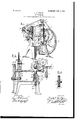
The invention also consists in providing the device with certain other new and useful features and in the peculiar arrangement and combination of parts, all as hereinaftermore fully described, and particularly pointed out in the claims, reference being had to the accompanying drawings, in which Figured is a perspective view of a device embodying my invention; Fig. 2, a longitudinal vertical section of the same, showing a modified form of work-supp ort attached; and Fig. 3 is an edge view of a modified form of work-supporting wheel.
A represents the base portion of the frame of the machine, and A and A two vertical standards or posts extending upward from the base, one at each end thereof, the standard A being hollow at its lower end and formed with vertical ways A on which ways is the bearing-block B, in which the shaft C is journaled near one end, its opposite end being journaled in the bearing-block C,
loosely held in an opening in the standard A The block B is vertically movable on its ways and is held in its upper position in engagement with the stops B by a spring D, which engages its lower side and extends downward within the hollow portion of the standard A to engage an adjusting-plug D,adjustably held in an opening into the bottom of the standard by adjusting-screws D said block being moved along its ways by a rod D attached to the lower side thereof and passed down through the axis of said spring and of said plug, where it is adapted to be connected to a suitable foot-lever or other operating mechanism at its lower end. The end of the shaft C adjacent to the block B is reduced, and on this reduced portion is secured a feed wheel E by a nut on the end of the shaft, a sleeve on the shaft between the wheel and the block preventing said shaft from moving longitudinally in one direction and a gearwheel F on the opposite end of said shaft in engagement with the opposite block C preventing said shaft from moving in the other direction. The face of the feed-wheel E is provided with a band of rubber E to form a friction-surface to engage the sole to be operated upon and feed the same forward.
A tool-supporting block G is secured between the upper ends of the ways A by the flanges G, which engage the ways at one side, and the cross-bar G which engages the opposite side of the ways and has a bindingscrew G extending through the bar and engaging a screw-threaded opening in the block to bind the flanges and bar against the sides of the ways and adjustably secure the block to the standard, which block is extended to form a seat for the tool H, which tool is adjustably secured to the upper face thereof by the set-screw H passing through a slot H in said tool. The outer end of the tool is grooved or cut away transversely to form a shoulder H to engage the under side of the lip and lift the same,and the feather or portion from which the lip is severed is firmly clamped between the wheel E and the lower side of said shoulder, said tool at the same time serving as a guide against which the sole is held. I
Secured to the upper end of the standard A by a set-screw I,passing through a slot in said standard,is a bracket I, which bracket is provided with a bearing in which is journaled a shaft J, extending at right angles to the shaft C, and upon one end of which shaft J is a pulley J, and upon the other end is secured a wiper-wheel K, revolving in a plane at right angles to the plane in which the feed-wheel E revolves, said wheel K being provided with wiper-teeth K, the contact sides and edges of which are rounded off to prevent the cutting of the lip.
To one side of the tool-block Gis adjustably secured the bracket L by set-screws L passing through vertical slots in the bracket, and upon this bracket is journaled the presserroll L, which extends longitudinally parallel with the plane in which the wiper-wheel revolves and adjacent to it to engage the lip after it has been turned by the wiper-wheel and press or roll the same down to set it, thus removing all tendency to spring back to its original position.
It is necessary that the relative positions of the wiper-wheel K and the tool H be accurately determined, so that the wiper-teeth will strike the lip at the proper place, and to aid in this adjustment the bracket I and block G are each provided with an ear I and an adjusting-screw 1 passes through an opening in one of the ears and engages a screw-threaded opening in the other, so that when the set-screw I is loosened the turning of the screw I will accurately determine the movement of the bracket.
A stub-shaft M is secured to the standard A near its lower end, and on this shalt is j ournaled a pinion N, which meshes with the gear-wheel F and transmits motion thereto from the drive-wheel N, which is secured to said pinion and also mounted on said shaft, and to the upper end of said standard is adjustably secured a bracket O by a set-screw O passing through a slot in the bracket and an adjusting-screw O engaging the upper end of the standard to raise and lower the bracket, on which bracket is journaled two idlers 0 over which the driving-belt P passes to transmit motion from the drive-wheel N to the pulley J to actuate the wiper-wheel K.
In the modification of the work supporting and feeding mechanism shown in Fig. 2 a bevel-gear Q is substituted for the feedwheel E, and a bracket Q, which is made detachable by being secured to the standard A by screw-bolts, extends outward beyond the end of the shaft 0 and is provided with a bearing for the vertical shaft R, u 3011 the upper end of which is secured to revo ve in a horizontal plane the feed wheel or table R, the lower side of said table being provided with a gear R to mesh with the gear Q. A spring S is sleeved on the lower end of the shaft and held thereon by a pin S passing through the shaft, the bracket being recessed to receive the spring and to furnish a shoulder against which it abuts. The shaft R has a free longitudinal movement in its bearing, and the spring S holds the gear R in mesh with the gear Q as the latter rises and falls, and so the table R is supported and revolved by the gear Q and pressed yieldingly upward by the spring D to clamp the feather of the sole between its upper face and the tool H. The upper face of th1s Wheel or table R is provided with a peripheral groove, in which is secured a band of rubber R to form a frictional contact-surface to prevent the sole from slipping. This horizontal work sup porting and feeding wheel is used when the sole or insole to be operated upon is thin and flexible, and therefore requires an extended supporting-surface to hold it up in a position to be effectively operated upon by the wiperwheel and presser-roll. The feed-wheel E, operating in a vertical instead of a horizontal position, contacts the sole at one point only, which is directly beneath the tool H, and therefore if the sole is very flexible thepresserroll L would have little effect on the lip, as the sole would not be supported directly beneath the said roll to hold it in contact therewith; but when the sole is quite rigid and thick the point at which the sole is supported is so nearly directly beneath the roll that the lip will be effectually rolled down.
On work where to roughen the surface contacted by the work supporting and feeding wheel will do no harm, such as McKay work, a positive feed may be used, as shown in Fig. 3, which consists in forming the wheel S of outer disks S and S the disk S being formed with a hub portion, and thin inner disks S of slightly larger diameter, between which is interposed the thin separating-disk S, which disks S are provided with teeth at their periphery and are firmly clamped between the outer disks in such a position that their teeth will not coincide, but will be staggered-that is, the teeth on one wheel will project outward at a point intermediate that of the,teeth on the other disk but on work where it is necessary that the surface be left perfectly smooth the rubber band is preferably used, and this form may be used in all cases except where the sole feeds through particularly hard.
By using a feed-wheel which revolves in a vertical plane to support the work the lips on soles which have been formed in a mold may be turned, and by employing a thin wheel to wipe or turn the lip the tool for raising the lip, the wheel for turning, and the roll for pressing it down may all lie very close together, and thus take up little space, so that in turning the lip on a pointed-toed sole the wheel and roll will not be thrown out of engagement with the li in going around the toe. The wiper-whee revolving at right angles to the path of the lip has a lifting and wiping action, which breaks the lip over, but cannot in any way out or injure it, the teeth being rounded or inclined opposite to the direction of revolution and also having their sides which contact the lip rounded off.
The several parts are all made adjustable, and by providing interchangeable work supporting and feeding wheels the machine may be employed to effectually turn the lips on any kind of work, and a simple, cheap, and very efiicient machine is secured.
Having thus fully described my invention, what I claim is 1. In a lip-turning machine, the combination with means for supporting and feeding the work, of a wiper-wheel revolving in a plane at right angles to the path of the lip and having peripheral wiper-teeth traversing the path of the lip.
2. In a lip-turning machine, the combination with means for supporting and feeding the work, of a wiper-wheel revolving in a plane at right angles to the path of the lip and having peripheral wiper-teeth traversing the path of the lip above the surface of the work.
3. In a lip-turning machine, the combination with means for supporting and feeding the work, of a revolving wi er-wheel operating in a plane at right ang es to the path of the lip for turning the lip and a presser for .setting the lip after passing the wiper-wheel.
4. In a lip-turning machine, the combination with means for supporting and feeding the work, of a lip-raising tool, a wiper-wheel traversing the path of the lipfor turning the lip and a resser-roll for setting the lip.
5. In a lip-turning machine, a revolving wiperwheel in a plane at right angles to the path of the lip and having wiper-teeth formed with rounded-ofi contactfaces for striking the lip above its base and turning the same.
6. In a lip-turning machine, the combination with means for supporting and feeding the work, of a wiper-wheel revolving in a plane at right angles to the path of the lip and adapted to turn the lip by a wiping contact therewith and means for holding the work in position against such contact.
7. In a lip-turning machine, in combination with the frame thereof, a lip-raising tool mounted upon the frame, a wiper-wheel revoluble in a plane at right angles to the path of the lip and adjacent to said tool, a presserroll adjustably secured to said frame and extending longitudinally across the path of the lip, a work-supportingwheel revoluble in a vertical plane, and means for yieldingly holding said wheel in'contact with the work to clamp the same between the tool and the wheel.
8. In a lip-turning machine, in combination with the frame thereof, a horizontal shaft mounted in movable bearings on said frame, a work supporting and feeding wheel on said shaft, a lip-raising guide adjustably secured on said frame, means for yieldinglysupporting the shaft to clamp the work between the wheel and said guide, a bracket adjustably secured to the frame, a shaft mounted on said bracket, a wiper-wheel on said shaft adjacent to the guide, .and a presser-roll adjacent to the wiper-wheel.
9. In a lip-turning machine, in combination with the frame thereof having vertical Ways, a bearing-block mounted on said ways, a shaft extending longitudinally of the frame and journaled and supported at one end on said block, a work supporting and feeding Wheel on saidshaft, a lip-raising guide on said frame extending over said wheel, a spring engaging said bearing-block to yieldingly clamp the work between the wheel and the guide, means for depressing said spring to lower the wheel, a bracket secured to the frame, a shaft mounted in a bearing on said bracket, a wiper-wheel revolving in a plane at right angles to the path of the lip and secured on the end of said shaft, and a bracket adjustably mounted on the frame adjacent to the wiperwheel and provided with a presser-roll extending across the path of the lip at right angles thereto.
10. In a lip-turning machine, in combination with the frame thereof, a bearing-block movable in vertical ways on said frame and a bearing-block secured in an opening in said frame and free to tilt therein, a horizontal shaft mounted in said bearings, a work supporting and feeding wheel on said shaft, a lipraising guide on said frame, a spring engaging the lower side of the movable bearingblock to hold the feed-wheel in contact with the work to clamp the same between the wheel and said guide, an adjusting-plug enaging the lower end of said-spring, means or adjusting and holding said plug, a rod secured to said movable block to move the same on its ways, and a wiper-wheel adjacent to the lip-raising guide revolving at right angles to the path of the lip.
11. In a lip-turning machine, in combination with the frame thereof having a vertical standard at each end thereof, one standard being provided with an opening and the other with vertical ways, a bearing-block in said opening and a bearing-block movable on said ways, a horizontal shaft mounted on said blocks, a work supporting and feeding wheel on said shaft, stops adapted to be engaged by the block on said ways, a coil spring engaging the lower side of said block at one end, an adjusting-plug projecting through an'opening in said frame and engaging the lower end of said spring and provided with an axial opening, means for adjusting said plug in the opening, a rod secured to the lower side of the block on the ways and extending downward through the spring and the opening in the plug, a lip-raising guide adjustably secured to the frame, a wiper-wheel revolving at right angles to the path of the lip and adjacent to the guide, a bracket adjustably secured to the frame, and a pressure-roll journaled on said bracket adjacent to the wiperwheel.
12. In a lip-turning machine, in combina tion with the frame thereof having vertical standards, a horizontal shaft mounted in movable hearings on said standards, a work feeding and supporting wheel secured on said shaft, a supporting-block adjustably secured to one of the standards, a lip-raising guide provided with a slot and adjustably secured to said block by a screw passing through said slot, a bracket adjustably secured to the block, a presser-roll journaled on
Priority Applications (1)
| Application Number | Priority Date | Filing Date | Title |
|---|---|---|---|
| US23135602A US809332A (en) | 1902-05-10 | 1902-05-10 | Lip-turner. |
Applications Claiming Priority (1)
| Application Number | Priority Date | Filing Date | Title |
|---|---|---|---|
| US23135602A US809332A (en) | 1902-05-10 | 1902-05-10 | Lip-turner. |
Publications (1)
| Publication Number | Publication Date |
|---|---|
| US809332A true US809332A (en) | 1906-01-09 |
Family
ID=2877813
Family Applications (1)
| Application Number | Title | Priority Date | Filing Date |
|---|---|---|---|
| US23135602A Expired - Lifetime US809332A (en) | 1902-05-10 | 1902-05-10 | Lip-turner. |
Country Status (1)
| Country | Link |
|---|---|
| US (1) | US809332A (en) |
-
1902
- 1902-05-10 US US23135602A patent/US809332A/en not_active Expired - Lifetime
Similar Documents
| Publication | Publication Date | Title |
|---|---|---|
| US809332A (en) | Lip-turner. | |
| US296535A (en) | Abrading-machine | |
| US1280639A (en) | Buffing-machine. | |
| US1869434A (en) | Edge trimmer and the like | |
| US1109199A (en) | Impression or imitation stitch machine. | |
| US1122245A (en) | Machine for scoring leather. | |
| US2128768A (en) | Roughing machine | |
| US1060759A (en) | Machine for grinding toe-caps and the like. | |
| US920488A (en) | Sole-edge-trimming machine. | |
| US1146529A (en) | Leather-buffing machine. | |
| US969183A (en) | Abrading-machine. | |
| US500438A (en) | Sole-channeling machine | |
| US838903A (en) | Skiving-machine. | |
| US1462792A (en) | Rib tightener for gem innersoles | |
| US1005394A (en) | Welt-laying machine. | |
| US1074726A (en) | Welt grooving and beveling machine. | |
| US588970A (en) | Channel-flap turner | |
| US484363A (en) | Channeling-machine | |
| US999482A (en) | Ball winding and rolling machine. | |
| US1206915A (en) | Skiving-machine. | |
| US861084A (en) | Automatic groove-cutting machine for wooden shoe-soles. | |
| US316006A (en) | busell | |
| US1726800A (en) | Sole machine | |
| US564169A (en) | Rounding-out machine for boot or shoe soles | |
| US477459A (en) | Leather-skiving machine |