US809305A - Electrical piano-player. - Google Patents
Electrical piano-player. Download PDFInfo
- Publication number
- US809305A US809305A US25762105A US1905257621A US809305A US 809305 A US809305 A US 809305A US 25762105 A US25762105 A US 25762105A US 1905257621 A US1905257621 A US 1905257621A US 809305 A US809305 A US 809305A
- Authority
- US
- United States
- Prior art keywords
- web
- electromagnets
- circuit
- player
- tracker
- Prior art date
- Legal status (The legal status is an assumption and is not a legal conclusion. Google has not performed a legal analysis and makes no representation as to the accuracy of the status listed.)
- Expired - Lifetime
Links
- QSHDDOUJBYECFT-UHFFFAOYSA-N mercury Chemical compound [Hg] QSHDDOUJBYECFT-UHFFFAOYSA-N 0.000 description 15
- 229910052753 mercury Inorganic materials 0.000 description 15
- 230000000284 resting effect Effects 0.000 description 8
- 230000000881 depressing effect Effects 0.000 description 7
- 239000000126 substance Substances 0.000 description 7
- 238000010276 construction Methods 0.000 description 6
- 239000004020 conductor Substances 0.000 description 4
- 230000001105 regulatory effect Effects 0.000 description 3
- 230000001276 controlling effect Effects 0.000 description 2
- 230000000994 depressogenic effect Effects 0.000 description 2
- 230000000694 effects Effects 0.000 description 2
- 238000004804 winding Methods 0.000 description 2
- 240000006122 Chenopodium album Species 0.000 description 1
- BBBFJLBPOGFECG-VJVYQDLKSA-N calcitonin Chemical compound N([C@H](C(=O)N[C@@H](CC(C)C)C(=O)NCC(=O)N[C@@H](CCCCN)C(=O)N[C@@H](CC(C)C)C(=O)N[C@@H](CO)C(=O)N[C@@H](CCC(N)=O)C(=O)N[C@@H](CCC(O)=O)C(=O)N[C@@H](CC(C)C)C(=O)N[C@@H](CC=1NC=NC=1)C(=O)N[C@@H](CCCCN)C(=O)N[C@@H](CC(C)C)C(=O)N[C@@H](CCC(N)=O)C(=O)N[C@@H]([C@@H](C)O)C(=O)N[C@@H](CC=1C=CC(O)=CC=1)C(=O)N1[C@@H](CCC1)C(=O)N[C@@H](CCCNC(N)=N)C(=O)N[C@@H]([C@@H](C)O)C(=O)N[C@@H](CC(N)=O)C(=O)N[C@@H]([C@@H](C)O)C(=O)NCC(=O)N[C@@H](CO)C(=O)NCC(=O)N[C@@H]([C@@H](C)O)C(=O)N1[C@@H](CCC1)C(N)=O)C(C)C)C(=O)[C@@H]1CSSC[C@H](N)C(=O)N[C@@H](CO)C(=O)N[C@@H](CC(N)=O)C(=O)N[C@@H](CC(C)C)C(=O)N[C@@H](CO)C(=O)N[C@@H]([C@@H](C)O)C(=O)N1 BBBFJLBPOGFECG-VJVYQDLKSA-N 0.000 description 1
- 230000000295 complement effect Effects 0.000 description 1
- 230000003292 diminished effect Effects 0.000 description 1
- 239000011810 insulating material Substances 0.000 description 1
- 239000002023 wood Substances 0.000 description 1
Images

Classifications
-
- G—PHYSICS
- G10—MUSICAL INSTRUMENTS; ACOUSTICS
- G10F—AUTOMATIC MUSICAL INSTRUMENTS
- G10F3/00—Independent players for keyboard instruments
Definitions
- My invention pertains to piano-players, more particularly piano-players of the electric type; and it has for one of its objects to provide a piano-player embodying a perforated web and simple and, reliable means whereby the web is enabled to automatically control-i. (3., increase and diminish the power employed, and thereby assure the power being at all times commensurate with the particular number of keys struck to make a single tone or a chord.
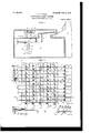
- FIG. 1 is a vertical section of the piano player constituting the present and preferred embodiment of my invention, the said player being shown in its proper position relative to the keyboard of a piano.
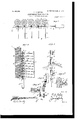
- FIG. 2 is an enlarged detail section taken from the rear and showing a portion of the mechanism for modulating the tones produced.
- Fig. 2' is a detail elevation of one sleeve.
- Fig. 3 is a detail horizontal section taken in the plane indicated by the line 3 3 of Fig. 2 looking down wardly.
- Fig. i is a detail view taken at right angles to Fig.
- Fig. 5 is an enlarged detail perspective view illustrating the relative arrangement of certain parts comprised in the tonemodulating mechanism and hereinafter referred to in detail.
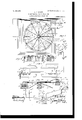
- Fig. 6 is a detail view illustrative of the gearing for causing the web-support and web to move slowly downward.
- Fig. 6 is a detail horizontal section, on an enlarged scale, illustrating a part of the mechanism for caus ing the web to be wound on the roller F when the web-supporting frame moves downwardly.
- Fig. 6 is a detail vertical section of the same.
- Fig. 7 is a top plan view of the means employed to regulate the volume of current supplied to the magnets for actuating the key-striking levers with a view of making the said volume commensurate with the number of keys to be struck at one time.
- Fig. 8 is a detail diametrical section of the said means.
- Fig. 9 is a broken view of the means employed to support the web in its active position.
- Fig. 10 is a detail enlarged section illustrative of two of the circuit-closeis comprised in the player.
- Fig. 11 is a top plan view illustrative of the web, &c.
- Fig. 12 is a diagrammatic view of the tonemodulating magnets and their circuits.
- A is a piano, which may be, and preferably is, of the conventional construction
- B B are electromagnets, of which there is one for each key of the piano.
- the said electromagnets are arranged upright and in a series parallel to the series of piano-keys, and each magnet is of the construction shown in Fig. 4 6. 0., comprises a core a and a wire helix I), wound in sections connected end to end at intervals and provided at the points of connection with terminals whereby various numbers of turns may be utilized, according to the force desired.
- each electromagnet E is upright electromagnets which correspond in number to the magnets B and are arranged in a series parallel to the series of piano-keys and the series of magnets B. Disposed above each electromagnet E is an upright rod F, which is provided at its lower end with an armature f and at intervals of its length with a plurality of, say, ten loose sleeves g, which are arranged below and held against undue upward movement by enlargements h on the rod and are provided with lateral slotted arms 71.
- these slotted arms "L are arranged the before-mentioned vertically-movable contact-pieces G, which are spring-strips, whereby they are adapted when the electromagnet E below the rod F is deenergized to raise the rod and normally support the same in its raised position.
- the loose leaves 9 are supported on the rods F by set-screws and from this it follows that the said sleeves 9 may be adjusted to take up wear or for any other purpose.
- I I are electromagnets, of which there are ten in the present embodiment of my invention.
- a bar J of conductive material, which is provided at one end with an armature 7c and at intervals of its length with enlargements Z, corresponding in number to the number of electromagnets B employed.
- the bars Jv are electrically connected, as hereinafter pointed out, with one pole of the source of electric energy employed to energize the magnets B and draw down the key-striking levers O. From this it follows that when one of the magnets I is energized and its bar J is drawn toward the right (see the second bar J from the top in Fig. 2) and one of the bars F is drawn downward by the energization of its magnet E the contactpieces G, engaged by the sleeves g of the particular bar F mentioned, will be drawn downward. It will be noticed, however, that no one of the contact-pieces G employed in combination with the said bar F will make an electrical contact except the contactpiece G adjacent to the second bar J from the top.
- a plurality of cups K, Figs. 1 and 10 Arranged in a series parallel to the series of piano-keys and the series of electromagnets E is a plurality of cups K, Figs. 1 and 10, containing mercury or other conductive material and corresponding in number to the said magnets E.
- the mercury in the several cups K is electrically connected. by wires m with one pole of a source of electric energy L, Fig. 10, the other pole of which is electrically connected by wires m with the several magnets E.
- Each of the magnets E is also electrically connected, through a wire on or other conductor, to a plate m, which in turn is electrically connected to an individual circuit-closer M, arranged to enter one of the cups K and make electric contact with the mercury therein contained.
- the circuitclosers M are normally held out of engagement with the mercuryin the cups K through the medium of a perforated web N, presently described, and the scheme of my invention is that when a certain perforation is presented to a particular circuit-closer M the said circuit-closer will be permitted to fall, and thereby complete an electric circuit through a particular magnet E and draw down the rod F above the said magnet for the purpose before set forth.
- P P are cups corresponding in number to the cups K, arranged in a series alongside the series of cups K and containing mercury or other suitable conductive substance.
- Q Q are circuit-closers corresponding in number to and arranged in pairs with the circuit-closers M, but electrically isolated from said circuit-closers M by insulating material p.
- R is a source of electrical energy with one pole of which the circuit-closers Q are electrically connected.
- Such electrical connection is made through a wire a, the cup d of the presently-described device U, a certain armaturelever 7t of said device U, the cup 7/ thereof, and a wire a, as diagrammatically shown in Fig. 10.
- circuit-closers Q are each provided with a depending beveled projection 7, which is adapted to take into apertures s in the web N, and thereby permit the circuit-closers M and Q to fall after the manner shown in Fig. 10. When one of the circuit-closers Q falls, the current will pass from one pole of the source of electrical energy It,
- the means U for regulating the volume of current supplied to one or more of the magnets B at one time.
- the said means which is shown in detail in Figs. 7 and 8, comprises a box a, a central cup Z), arranged in said box and containing mercury or the like 0, electrically connected, through wire a as shown in Figs. 7 and 10, with one pole of the source of energy R, a cup d, containing mercury or the like and designed to trio energy V, with one pole of which all of thebe electrically connected with the opposite pole of the source of energy R, and eleven similar cups 6, also containing mercury or the like.
- It also comprises resistancecoilsf, extending between the cups d and e and also between the cups a, twelve electromagnets g, arranged in a circular series, twelve armaturelevers 7t, normally held in the positions shown in Fig. 8 by coiled springs 7c or other means and having inner depending portions disposed in the mercury of the cup Z), and outer depending portions adapted to be moved down into the mercury in the cups cZ e, a source of elecelectromagnets g are electrically connected, as diagrammatically shown in Fig. 7, twelve circuit-closers Z, similar in construction to the circuit-closers Q, and twelve cups m, containing mercury or the like and each elec trically connected. with one of the electro magnets g.
- the circuit between the cup (Z of the meansU and one pole of the source of energy R is through the wire a, one or more of the circuit-closers Q, the respective mercury cup or cups P thereof, one or more of the wires T, one or more of the magnets B, one or more of the terminals 0 thereof, one or more of the contact-pieces G, one or more of the bars J, and the wire S. It is obvious that the number of cups 6, electromagnets g, armature levers h, circuit-closers Z, and cups m may be increased or diminished, as desired, without involving a departure from my invention.
- the circuit-closers Z are normally supported out of contact with the mercury in their cups m by the web N, and the scheme of my invention is to present a perforation Z in the web N to one of the said circuit-closers, according to the volume of current it is desired to supply to the electromagnets B, precedent to the energization of the said magnets B by the de pression of their complementary circuitclosers Q.
- the said perforation Z in the web for permitting depression of one of the circuit-closers Z is arranged in advance of the group of perforations Q for permitting the depression of a group of circuit-closers Q, and in this way the volume of current supplied to the electromagnets B is made commensurate with the number of magnets B energized at one time.
- a perforation Z is provided in the web in advance of the said twelve perforations and in position to permit depression of the first circuit-closer Z toward the left in Fig. 7.
- the magnet g inradial alinement with the cup d of the means for controlling current will be energized and the armature-lever of said magnet will be drawn downwardly.
- the electromagnet g for supplying the proper volume of current is energized.
- the magnet g between which and the cup (1 there are eleven resistance-coils, is energized when but one magnet B is to be energized at one time from the source of electric energy R.
- the magnets I are electrically connected with one pole of a source of electrical energy A and are also electrically connected to individual cups B containing mercury or the like.
- circuit-closers C which are similar in construction to the circuit-closers Q, are normally supported out of the mercury in their cups B by the web N, are controlled by the web, and are connected with the opposite pole of the source of energy A.
- any one of the circuit-closers C is permitted to move downwardly, its respective magnet I will be energized for the purpose before described, and as the magnets I must be energized precedent to the energization of the magnets E and B the perforation C in the web N for energizing one of the magnets I must precede the perforations for energizing the magnets E and B in the order named.
- a second magnet I maybe energized immediately before another of said magnets is denergized, as when it is desired to have the second magnet in radiness for a different (stronger or weaker) variation.
- the said electromagnets L are electrically connected with one pole of a source of electric energy M and are also electrically connected with a cup N containing mercury or the like.
- a circuit-closer P similar to the circuitclosers Q, before described, is employed in connection with the cup i and said circuit-closer is electrically connected with the opposite pole of the source of electric energy N hen the circuit-closer P is permitted to move downwardly by a perforation in the web N, the electromagnets L will be energized, and hence will operate to draw the armaturelatches K out of the notches in the uprights H, thereby permitting the uprights H, the tracker D, and the web N to move downwardly, so as to admit of the said web being wound off the roller G and on the roller F without interference from the projections r of the several resilient circuit-closers.
- A is a shaft designed to be rotated in the direction indicated by arrow through the medium of an electromotor X.
- B is a shaft for rotating the roller G;
- C a shaft for rotating the roller F;
- D a spurgear movable longitudinally on the shaft A E F and F spur-gears for transmitting motion from the gear D to the shaft B when said gear D is in one position, and G H, and H spur-gears for transmitting motion from the gear D to the shaft (7 when said gear D is in its other position.
- the gear D is feathered on shaft A Figs.
- anv suitable means may be employed, such as the switch X, which is shown in F ig. 1]. as in circuit with the electromotor X
- the train of gears shown in Fig. 6 is designed by the friction it affords to retard. the web-supporting frame in its downward movement, and thereby prevent said frame from falling rapidly, the gear P of said train being intermeshed with a rack P on an adjacent up right H of the said frame and being designed when the frame is to be raised by hand to be moved laterally out of engagen'lent with said rack, so as not to interfere with the quick raising of the frame.
- the web N may be and preferably is provided with a longitudinal portion a allotted to perforations Q? for permitting depression of the circuit-closers Q M, of which a plurality are diagrammatically illustrated; a loi'igitudinal portion b, allotted to perforations Z for permitting depression of the circuit-closers Z, of which two are illustrated a longitudinal portion 0 allotted to perforations C for permitting depression of the circuit-closers C, of which two are shown,
- the circuit-closer P which is preferably similar in construction to the circuit-closer M, Fig. 10, is designed when the circuit-closer I falls to break the circuits of the magnets having circuit-closers controlled by the perforated web, this through the medium of the ordinary well-known construction, which I have deemed it unnecessary to illustrate.
- the combination of striking devices provided with armatures, electromagnets disposed below said armatures and having terminals at intervals in the length of their helices and vertically-movable contactpieces connected with said terminals, vertically-movable bars arranged to depress the contact-pieces and having armatures, electromagnets disposed below said armatures, horizontally-movable bars having enlargements normally resting out of vertical alinement with the contact-pieces, and also having armatures, and electromagnets for moving said bars horizontally.
- the combination of striking devices provided with armatures, electromagnets disposed below said armatures and having terminals at intervals the length of their helices and vertically-movable contactpieces connected with said terminals, vertically-movable bars having armatures, sleeves movable vertically on said bars and having loops receiving the contactpieces, adjustable devices for supporting the sleeves on the vertical bars, electromagnets disposed below the armatures of the vertical bars, horizontally movable bars having enlargements normally resting out of vertical alinement with the contactpieccs and also having armatures, and electromagnets for moving said bars horizontally.
- the combination of striking devices provided with armatures, electromagnets disposed below said armatures and having terminals at intervals in the length of their helices, a support, vertically-movable contact-pieces connected to said terminals and the support, vertically-movable bars having armatures, sleeves movable vertically on said bars and having loops receiving the contact-pieces, set-screws adjustable in bearings on the bars and supporting the sleeves, electromagnets disposed below the armatures of the vertical bars, horizontally-movable bars having enlargements normally resting out of vertical alinement with the contactpieces and also having armatures, and electromagnets for moving said bars horizontally.
- a tracker having a depression in its upper side, a web arranged to travel over said tracker and having perforations, electromagnets for depressing the striking devices; said electromagnets having terminals at intervals in the length of their helices and movable contactpieces connected with said terminals, circuit-closers arranged above the tracker and having beveled projections adapted to fall through openings in the web and into the depression of the tracker; said circuit-closers being electrically connected with the said electromagnets and a source of electrical energy, electromechanical means for moving the said contactpieces, circuit-closers arranged above the tracker and having beveled projections adapted to 1 fall through openings in the web and into the depression of the tracker; said circuit-closers being electrically connected with the said electromechanical means and a source of electrical energy, bars having portions designed to be engaged by said contact-pieces; said portions normally resting out of alinement with the contact-pieces,
- a vertically movable tracker a web movable over the tracker, means for normally supporting the tracker, electromechanical means controlled by the web for releasing the tracker and permitting the same to move downwardly at a predetermined time, striking devices, electromagnets controlled by the web and arranged to depress the striking devices, and eleetromechanical means controlled by the web and arranged to take current from the helices of said electromagnets at intervals in the length thereof.
- a vertically-movable tracker having a notch, a web movable over said tracker, an armaturelatch normally resting in the notch of the tracker, an electromagnet arranged adjacent to said armature-latch, and means controlled by the web for energizing the electromagnet at a predetermined time.
- a vertically-movable tracker having a notch, a web movable over the tracker, striking devices, electromagnets controlled by the web and ar ranged to depress the striking devices, electromechanical means controlled by the web and arranged to carry current from the helices of said electromagnets at different points in the length thereof, an armature-latch normally resting in the notch of the tracker, an electromagnet arranged adjacent to the armature-latch, and means controlled by the web for energizing the said magnet at a predetermined time.
- a web striking devices, electromagnets controlled by the web for depressing the said striking devices, a source of electrical energy, a receptacle containing conductive substance and connected with the source of electrical energy, a second receptacle containing conductive substance electrically connected with the electromagnets, a plurality of receptacles e011- taining conductive substance and connected by resistances with the second-mentioned receptacle, armatures for connecting the firstmentioned receptacle and theplurality of receptacles, electromagnets controlling said armatures, and means controlled by the web for energizing said electromagnets.
- aweb a source of electrical energy
- a receptacle containing conductive substance and electrically connected with the source of electrical energy a second receptacle containing conductive substance
- striking devices electromagnets controlled by the web and connected with the second-mentioned receptacle for depressing the striking devices
- a plurality of receptacles containing conductive substance connected by resistances with the secondmentioned receptacle armatures for electrically connecting the first and second men tioned receptacles, magnets for moving said armatures, and means controlled by the web for energizing said magnets.
- a vertically-movable tracker In a player for pianos and other musical instruments, the combination of a vertically-movable tracker, a web movable over the tracker, means for winding the web from one roller to another, the said rollers, a driving connection for the rollers, movable means controlled by the web for normally supporting the tracker and means controlled by the Web for reversing the driving connection.
- a web In a player for pianos and other musical instruments, the combination of a web, a vertically-movable tracker supporting the same, means for normally supporting the tracker, electromechanical means controlled. by the web and arranged to release the tracker and permit the same to move downwardly at a predetermined time, striking devices, electromagnets controlled by the web and arranged to actuate the striking devices means controlled by the web and arranged to regulate the strength of the blows of the striking devices, and means controlled by the web for to the electromagnets.
- a web In a player for pianos and other musical instruments, the combination of a web, a vertically-movable tracker supporting the same, means for supporting the tracker, electromechanical means controlled by the web and arranged to release the tracker and to permit the same to move downwardly at a predetermined time, striking devices, electromagnets controlled by the web and arranged to actuate the striking devices, means conl trolled by the web and arranged to regulate the strength of the blows of the striking devices, means controlled by the web for regulating the volume of current supplied to the electromagnets, means controlled by the web for reversing the direction of movement of the web when the trackermoves downwardly, and means controlled by the web for break I ing the circuits connected with the electro magnets for actuating the striking devices.
Landscapes
- Physics & Mathematics (AREA)
- Engineering & Computer Science (AREA)
- Acoustics & Sound (AREA)
- Multimedia (AREA)
- Electromagnets (AREA)
Description
N. 09305. PATENTED JAN. 19 0 8 P. B. KEHOE. 06
ELEOTRIGAL PIANO PLAYER.
APPLICATION FILED APR-27. 1905.
4 snnn'rs-snnm 1.
E I w'whmowa G f6,
1 5751; 5L 61mm,
No. 809,305. PATENTED JAN. 9, 1906. P. B, KBHOE.
ELECTRICAL PIANO PLAYER.
APPLICATION FILED APBHZI, 1905.
4 SHEETS-SHEET Z.
uuawto r,
Witt wow:
No. 809,305. PATENTED JAN. 9, 1906. P. B. KEHOE.
ELECTRICAL PIANO PLAYER.
APPLICATION FILED APR.27.1905.
4 SHEETS-SHEET 3-,
nvzwto'b J W [7 v I N0. 809,305. PATENTBD JAN. 9, 1906. P. B. KBHOE. ELECTRICAL PIANO PLAYER.
APPLICATION FILED APR.27. 1905.
4 SHEETS-SHEET 4.
Witnuom' PANNELL B. KEHOE, ()F FLEMlNGSBUR-G, KENTUCKY.
ELECTRICAL PIANO-PLAYER.
Specification of Letters Patent.
Patented Jan. 9, 1906.
Application filed April 27,1905. Serial No. 257.621.
10' Ml who/n it 7Tuity concern.-
Be it known that I, PANNELL B. KEnon, a citizen of the United States, residing at Flemingsburg, in the county of Fleming and State of Kentucky, have invented new and useful.
Improvements in Electrical Piano-Players, of which the following is a specification.
My invention pertains to piano-players, more particularly piano-players of the electric type; and it has for one of its objects to provide a piano-player embodying a perforated web and simple and, reliable means whereby the web is enabled to automatically control-i. (3., increase and diminish the power employed, and thereby assure the power being at all times commensurate with the particular number of keys struck to make a single tone or a chord.
Another object of the invention is the provision, in a pianoplayer,of means controlled by the perforated web and through the medium of which the music produced may be nicely modulated and fine effects as regards expression attained; and another object is the provision in a piano-player embodying a perforated web, of automatic means for putting the web out of its operating position when the end of a piece of music is reached and rewinding the web on the roller, from whence it is taken incident to the playing of a piece of music.
Other objects and advantages of the invention will be fully understood from the following description and claims when taken in connection with the accompanying drawings, forming part of this specification, in which Figure 1 is a vertical section of the piano player constituting the present and preferred embodiment of my invention, the said player being shown in its proper position relative to the keyboard of a piano. Fig. 2 is an enlarged detail section taken from the rear and showing a portion of the mechanism for modulating the tones produced. Fig. 2' is a detail elevation of one sleeve. Fig. 3 is a detail horizontal section taken in the plane indicated by the line 3 3 of Fig. 2 looking down wardly. Fig. i is a detail view taken at right angles to Fig. 2 in the plane indicated by the line 4 4 of said figure and illustrating one of the electromagnets, the energization of which is adapted to actuate one key-strik ing lever, and also illustrating the parts appurtenant to the said electromagnet. Fig.
5 is an enlarged detail perspective view illustrating the relative arrangement of certain parts comprised in the tonemodulating mechanism and hereinafter referred to in detail. Fig. 6 is a detail view illustrative of the gearing for causing the web-support and web to move slowly downward. Fig. 6 is a detail horizontal section, on an enlarged scale, illustrating a part of the mechanism for caus ing the web to be wound on the roller F when the web-supporting frame moves downwardly. Fig. 6 is a detail vertical section of the same. Fig. 7 is a top plan view of the means employed to regulate the volume of current supplied to the magnets for actuating the key-striking levers with a view of making the said volume commensurate with the number of keys to be struck at one time. Fig. 8 is a detail diametrical section of the said means. Fig. 9 is a broken view of the means employed to support the web in its active position. Fig. 10 is a detail enlarged section illustrative of two of the circuit-closeis comprised in the player. Fig. 11 is a top plan view illustrative of the web, &c. Fig. 12 is a diagrammatic view of the tonemodulating magnets and their circuits.
Similar letters designate corresponding parts in all of the views of the drawings, referring to which A is a piano, which may be, and preferably is, of the conventional construction, and B B are electromagnets, of which there is one for each key of the piano. The said electromagnets are arranged upright and in a series parallel to the series of piano-keys, and each magnet is of the construction shown in Fig. 4 6. 0., comprises a core a and a wire helix I), wound in sections connected end to end at intervals and provided at the points of connection with terminals whereby various numbers of turns may be utilized, according to the force desired. Through the medium of the magnets B and the key-striking levers C, of which there is one fol each piano-key and each magnet B, the two functions of depressing the keys and modulating the tones are accomplished. T he said key-striking levers C are fulcrumed at (Z in the case D of the player and are normally held in the raised position (shown in Fig. 1) by springs e or other means compatible with the purposes of my invention. The contact-pieces G and the terminals 0 are connected together in any manner that will permit current to pass from the latter to the former. a
E E are upright electromagnets which correspond in number to the magnets B and are arranged in a series parallel to the series of piano-keys and the series of magnets B. Disposed above each electromagnet E is an upright rod F, which is provided at its lower end with an armature f and at intervals of its length with a plurality of, say, ten loose sleeves g, which are arranged below and held against undue upward movement by enlargements h on the rod and are provided with lateral slotted arms 71. In these slotted arms "L are arranged the before-mentioned vertically-movable contact-pieces G, which are spring-strips, whereby they are adapted when the electromagnet E below the rod F is deenergized to raise the rod and normally support the same in its raised position. There are preferably ten of these contact-pieces G employed in combination with each electromagnet B and each rod F, as best shown in Fig. 4, and they are connected at their ends remote from the magnet B to a suitable support II, of wood or other non-conducting material, fixed in the case D, and have their opposite ends in permanent engagement with the terminals 0. The loose leaves 9 are supported on the rods F by set-screws and from this it follows that the said sleeves 9 may be adjusted to take up wear or for any other purpose.
I I are electromagnets, of which there are ten in the present embodiment of my invention. In alinement with each of the said magnets I is a bar J, of conductive material, which is provided at one end with an armature 7c and at intervals of its length with enlargements Z, corresponding in number to the number of electromagnets B employed.
The bars Jv are electrically connected, as hereinafter pointed out, with one pole of the source of electric energy employed to energize the magnets B and draw down the key-striking levers O. From this it follows that when one of the magnets I is energized and its bar J is drawn toward the right (see the second bar J from the top in Fig. 2) and one of the bars F is drawn downward by the energization of its magnet E the contactpieces G, engaged by the sleeves g of the particular bar F mentioned, will be drawn downward. It will be noticed, however, that no one of the contact-pieces G employed in combination with the said bar F will make an electrical contact except the contactpiece G adjacent to the second bar J from the top. This being so, it will be seen that when current is supplied to the first electromagnet B-i. 6., the one at the right of Fig. 2-to energize the said magnet B and draw down its key-striking lever C the current will be taken from the particular magnet B, through the second terminal 0, from the top thereof, the adjacent contact-piece G, and the enlargement Z of the bar J, on which said contact-piece G bears, and as a result the tone produced will be next to the softest which it is possible to produce. It will also be observed that following the energization of the second magnet I from the top the depression of any one or more of the rods F will result in current being taken from said magnets B through the terminals 0 mentioned, the contact-pieces G, and the second bar J from the top.
Arranged in a series parallel to the series of piano-keys and the series of electromagnets E is a plurality of cups K, Figs. 1 and 10, containing mercury or other conductive material and corresponding in number to the said magnets E. The mercury in the several cups K is electrically connected. by wires m with one pole of a source of electric energy L, Fig. 10, the other pole of which is electrically connected by wires m with the several magnets E. Each of the magnets E is also electrically connected, through a wire on or other conductor, to a plate m, which in turn is electrically connected to an individual circuit-closer M, arranged to enter one of the cups K and make electric contact with the mercury therein contained. The circuitclosers M are normally held out of engagement with the mercuryin the cups K through the medium of a perforated web N, presently described, and the scheme of my invention is that when a certain perforation is presented to a particular circuit-closer M the said circuit-closer will be permitted to fall, and thereby complete an electric circuit through a particular magnet E and draw down the rod F above the said magnet for the purpose before set forth.
P P are cups corresponding in number to the cups K, arranged in a series alongside the series of cups K and containing mercury or other suitable conductive substance.
Q Q are circuit-closers corresponding in number to and arranged in pairs with the circuit-closers M, but electrically isolated from said circuit-closers M by insulating material p.
R is a source of electrical energy with one pole of which the circuit-closers Q are electrically connected. Such electrical connection is made through a wire a, the cup d of the presently-described device U, a certain armaturelever 7t of said device U, the cup 7/ thereof, and a wire a, as diagrammatically shown in Fig. 10.
S is an electrical connection between the before-mentioned bars J and the other pole of the source of electric energy R, and T is an electrical connection, of which there is one between each electromagnet B and its respective cup P. The circuit-closers Q are each provided with a depending beveled projection 7, which is adapted to take into apertures s in the web N, and thereby permit the circuit-closers M and Q to fall after the manner shown in Fig. 10. When one of the circuit-closers Q falls, the current will pass from one pole of the source of electrical energy It,
through the wire a, the cup Z), one of the armature-levers h, one or more of the resistance-coils, and the cup cZ of the means U, the wire a", the said circuit-closer Q,its respective cup P, one electrical circuit T, the respective magnet B of said circuit-closer Q, one of the terminals 0 of said magnet, one of the contact-pieces G, one of the bars J, and back through the wire S to the other pole of the source of electric energy. This will obviously energize the particular magnet B mentioned for the purpose set forth. It will also be no ticed by reference to Fig. 10 that because of the depending portion of the circuit-closer M being longer than the corresponding portion of the circuit-closer Q and themercury in the cups K and B being of a common height the respective magnet E of the particular mag net B mentioned will be energized immediately before the energization of said magnet B.
In the electrical circuit between the circuit-closers Q for energizing the electromagnets B and the source of electric energy R is, as before mentioned, the means U for regulating the volume of current supplied to one or more of the magnets B at one time. The said means, which is shown in detail in Figs. 7 and 8, comprises a box a, a central cup Z), arranged in said box and containing mercury or the like 0, electrically connected, through wire a as shown in Figs. 7 and 10, with one pole of the source of energy R, a cup d, containing mercury or the like and designed to trio energy V, with one pole of which all of thebe electrically connected with the opposite pole of the source of energy R, and eleven similar cups 6, also containing mercury or the like. It also comprises resistancecoilsf, extending between the cups d and e and also between the cups a, twelve electromagnets g, arranged in a circular series, twelve armaturelevers 7t, normally held in the positions shown in Fig. 8 by coiled springs 7c or other means and having inner depending portions disposed in the mercury of the cup Z), and outer depending portions adapted to be moved down into the mercury in the cups cZ e, a source of elecelectromagnets g are electrically connected, as diagrammatically shown in Fig. 7, twelve circuit-closers Z, similar in construction to the circuit-closers Q, and twelve cups m, containing mercury or the like and each elec trically connected. with one of the electro magnets g. The circuit between the cup (Z of the meansU and one pole of the source of energy R is through the wire a, one or more of the circuit-closers Q, the respective mercury cup or cups P thereof, one or more of the wires T, one or more of the magnets B, one or more of the terminals 0 thereof, one or more of the contact-pieces G, one or more of the bars J, and the wire S. It is obvious that the number of cups 6, electromagnets g, armature levers h, circuit-closers Z, and cups m may be increased or diminished, as desired, without involving a departure from my invention. The circuit-closers Z are normally supported out of contact with the mercury in their cups m by the web N, and the scheme of my invention is to present a perforation Z in the web N to one of the said circuit-closers, according to the volume of current it is desired to supply to the electromagnets B, precedent to the energization of the said magnets B by the de pression of their complementary circuitclosers Q. The said perforation Z in the web for permitting depression of one of the circuit-closers Z is arranged in advance of the group of perforations Q for permitting the depression of a group of circuit-closers Q, and in this way the volume of current supplied to the electromagnets B is made commensurate with the number of magnets B energized at one time. For instance, if twelve perforations Q are provided in the web in position to energize twelve of the electromagnets B at one and the same time a perforation Z is provided in the web in advance of the said twelve perforations and in position to permit depression of the first circuit-closer Z toward the left in Fig. 7. When the particular circuitcloser Z mentioned is depressed, the magnet g inradial alinement with the cup d of the means for controlling current will be energized and the armature-lever of said magnet will be drawn downwardly. As a result of this the full volume of current will pass from one pole of the source of electric energy B through wire a to the cup Z) and from said cup through the armature-lever h and the cup (Z mentioned to the respective circuit closers Q of the twelve electromagnets B mentioned and thence through the terminals 0, contactpieces G, and bar J back to the opposite pole of the source of energy R. If ten perforations Q are provided in the web in position to energize ten of the magnets B at one and the same time, a perforation Z is provided in the web in advance of the said ten perforations Q and in position to permit depression of the third circuit-closer Z from the left in Fig. 7. hen said circuit-closer Z is depressed, the respective magnet g of the second cup (5 from the cup (Z, counting toward the left, will be energized, and hence the current supplied to the ten magnets will pass from one pole of the source of energy R, through the wire a, the cup Z), the respective armature-lever of the magnet g mentioned, the cup 6, and two of the resistance-coils 1 before it reaches the cup cZ, from whence it passes through wire a to the ten circuitclosers Q of the ten electromagnets B to be energized, the said magnets B, and back through the terminals 0, contact-pieces G, bar J, and wire S to the opposite pole of the source of energy R. If current is to be supplied to less than ten magnets B at one and the same time, the electromagnet g for supplying the proper volume of current is energized. The magnet g, between which and the cup (1 there are eleven resistance-coils, is energized when but one magnet B is to be energized at one time from the source of electric energy R.
As shown diagrammatically in Fig. 12, the magnets I are electrically connected with one pole of a source of electrical energy A and are also electrically connected to individual cups B containing mercury or the like. In combination with the said cups B are circuit-closers C, which are similar in construction to the circuit-closers Q, are normally supported out of the mercury in their cups B by the web N, are controlled by the web, and are connected with the opposite pole of the source of energy A. lVhen any one of the circuit-closers C is permitted to move downwardly, its respective magnet I will be energized for the purpose before described, and as the magnets I must be energized precedent to the energization of the magnets E and B the perforation C in the web N for energizing one of the magnets I must precede the perforations for energizing the magnets E and B in the order named. l/Vhen deemed necessary, a second magnet I maybe energized immediately before another of said magnets is denergized, as when it is desired to have the second magnet in radiness for a different (stronger or weaker) variation.
As shown in the drawings, the web N is supported in its active position by a tracker D, having a groove E in its upper side, and is designed, incident to the playing of a piece of music, to be moved in the direction indicated by arrow off one roller F and on another roller G. These rollers preferably are removable from the player The tracker D is supported by uprights H, Fig. 9, which are guided in a crossbar I and are provided in their inner sides with notches J. These notches are designed to receive spring-pressed armature-latches K, which have for their purpose to hold the uprights H and the bar D against downward movement while a piece of music is being played. Adjacent to the said armature-latches K and on the bar I are arranged electromagnets L. The said electromagnets L are electrically connected with one pole of a source of electric energy M and are also electrically connected with a cup N containing mercury or the like. A circuit-closer P, similar to the circuitclosers Q, before described, is employed in connection with the cup i and said circuit-closer is electrically connected with the opposite pole of the source of electric energy N hen the circuit-closer P is permitted to move downwardly by a perforation in the web N, the electromagnets L will be energized, and hence will operate to draw the armaturelatches K out of the notches in the uprights H, thereby permitting the uprights H, the tracker D, and the web N to move downwardly, so as to admit of the said web being wound off the roller G and on the roller F without interference from the projections r of the several resilient circuit-closers. A", Figs. 6 and 11, is a shaft designed to be rotated in the direction indicated by arrow through the medium of an electromotor X. B is a shaft for rotating the roller G; C, a shaft for rotating the roller F; D a spurgear movable longitudinally on the shaft A E F and F spur-gears for transmitting motion from the gear D to the shaft B when said gear D is in one position, and G H, and H spur-gears for transmitting motion from the gear D to the shaft (7 when said gear D is in its other position. The gear D is feathered on shaft A Figs. 6" and 11, and is connected with the web-supporting frame through the medium of lever P and an endwise-movable rod P", disposed in the notch P of one upright H, Figs. 6 and (3", and hence it will be observed that when the said frame moves downwardly the gear D will be shifted out of engagement with the gear E and into engagement with the gear G this to effect winding of the web on the roller F. hen the frame formed by the uprights H and the bar D is raised, which operation is preferably accomplished by hand, a spring K, surrounding the .rod P and interposed between a collar K thereon and a stationary guide K", will return the rod to the position shown in Fig. 6" relative to the upright H, and thereby move the gear D" into engagement with the gear E", so as to reestablish the movement of the web in the direction indicated by arrow in Fig. 1.
To stop the motor when the web-supporting frame is in its lower position and the web has been wound on the roller F, anv suitable means may be employed, such as the switch X, which is shown in F ig. 1]. as in circuit with the electromotor X The train of gears shown in Fig. 6 is designed by the friction it affords to retard. the web-supporting frame in its downward movement, and thereby prevent said frame from falling rapidly, the gear P of said train being intermeshed with a rack P on an adjacent up right H of the said frame and being designed when the frame is to be raised by hand to be moved laterally out of engagen'lent with said rack, so as not to interfere with the quick raising of the frame.
As shown in Fig. 1], the web N may be and preferably is provided with a longitudinal portion a allotted to perforations Q? for permitting depression of the circuit-closers Q M, of which a plurality are diagrammatically illustrated; a loi'igitudinal portion b, allotted to perforations Z for permitting depression of the circuit-closers Z, of which two are illustrated a longitudinal portion 0 allotted to perforations C for permitting depression of the circuit-closers C, of which two are shown,
and a longitudinal portion (Z allotted to a perforation d for permitting depression of the circuit-closer P, and a perforation (Z for permitting depression of a circuit-closer P presently described.
The circuit-closer P which is preferably similar in construction to the circuit-closer M, Fig. 10, is designed when the circuit-closer I falls to break the circuits of the magnets having circuit-closers controlled by the perforated web, this through the medium of the ordinary well-known construction, which I have deemed it unnecessary to illustrate.
While I have illustrated an individual source of electric energy for the electromotor and individual sources of electric energy for the electromagnets B, E, and I and g, I desire it understood that one or more sources of electric energy common to all of the said elements may be employed without involving a departure from the scope of my invention.
Having described my invention, what I claim, and desire to secure by Letters Patent, is
1. In a player for pianos and other musical instruments, the combination of striking devices, electromagnets for depressing the striking devices; said electromagnets having terminals at intervals in the'length of their helices and movable contact-pieces connected with said terminals, electromechanical means for moving the said contact-pieces, bars having portions designed to be engaged 'by said contact-pieces; said portions normally resting out of alinement with the contact-pieces, and electromechanical means for moving the bars to carry the said portions thereof into alinement with the contactpieces.
2. In a player for pianos and other musical instruments, the combination of striking devices provided with armatures, electromagnets disposed below said armatures and having terminals at intervals in the length of their helices and vertically-movable contactpieces connected with said terminals, vertically-movable bars arranged to depress the contact-pieces and having armatures, electromagnets disposed below said armatures, horizontally-movable bars having enlargements normally resting out of vertical alinement with the contact-pieces, and also having armatures, and electromagnets for moving said bars horizontally.
3. In a player for pianos and other musical instruments, the combination of striking devices provided with armatures, electromagnets disposed below said armatures and having terminals at intervals the length of their helices and vertically-movable contactpieces connected with said terminals, vertically-movable bars having armatures, sleeves movable vertically on said bars and having loops receiving the contactpieces, adjustable devices for supporting the sleeves on the vertical bars, electromagnets disposed below the armatures of the vertical bars, horizontally movable bars having enlargements normally resting out of vertical alinement with the contactpieccs and also having armatures, and electromagnets for moving said bars horizontally.
l. In a player for pianos and other musical instruments, the combination of striking devices provided with armatures, electromagnets disposed below said armatures and having terminals at intervals in the length of their helices, a support, vertically-movable contact-pieces connected to said terminals and the support, vertically-movable bars having armatures, sleeves movable vertically on said bars and having loops receiving the contact-pieces, set-screws adjustable in bearings on the bars and supporting the sleeves, electromagnets disposed below the armatures of the vertical bars, horizontally-movable bars having enlargements normally resting out of vertical alinement with the contactpieces and also having armatures, and electromagnets for moving said bars horizontally.
5. In a player for pianos and other musical instruments, the combination of a web, striking devices, electromagnets for depressing the striking devices said electromagnets having terminals at intervals in the length of their helices and movable contact-pieces connected with said terminals, means controlled by the web for energizing said electromagnets, electromechanical means for moving the said contact-pieces, means controlled by the web for energizing said electromechanical means, bars having portions designed to be engaged by said contact-pieces; said portions normally resting out of alinement with the contactpieces, electromechanical means for moving the bars to carry the said portions thereof into alinement with the contactpieces, and means controlled by the web for energizing the latter electromechanical means.
6. In a player for pianos and other musical instruments, the combination of a tracker having a depression in its upper side, a web arranged to travel over said tracker and having perforations, electromagnets for depressing the striking devices; said electromagnets having terminals at intervals in the length of their helices and movable contactpieces connected with said terminals, circuit-closers arranged above the tracker and having beveled projections adapted to fall through openings in the web and into the depression of the tracker; said circuit-closers being electrically connected with the said electromagnets and a source of electrical energy, electromechanical means for moving the said contactpieces, circuit-closers arranged above the tracker and having beveled projections adapted to 1 fall through openings in the web and into the depression of the tracker; said circuit-closers being electrically connected with the said electromechanical means and a source of electrical energy, bars having portions designed to be engaged by said contact-pieces; said portions normally resting out of alinement with the contact-pieces, electromechanical means for moving the bars to carry the said portions thereof into alinement with the contact pieces, and circuit closers arranged above the tracker and having beveled projections adapted to fall through openings in the web and into the depression of the tracker; said circuit-closers being electrically connected with the latter electromechanical means and a source of electrical energy.
7. In a player for pianos and other musical instruments, the combination of striking devices, electromagnets for depressing the striking devices, and electromechanical means for carrying current from the helices of said electromagnets at different points in the length thereof.
8. In a player for pianos and other musical instruments, the combination of striking devices, a web, electromagnets controlled by the web and arranged to depress the striking devices, and electromechanical means controlled by the web and arranged to carry current from the helices of said electromagnets at different points in the length thereof.
9. In a player for pianos and other musical instruments, the combination of a vertically movable tracker, a web movable over the tracker, means for normally supporting the tracker, electromechanical means controlled by the web for releasing the tracker and permitting the same to move downwardly at a predetermined time, striking devices, electromagnets controlled by the web and arranged to depress the striking devices, and eleetromechanical means controlled by the web and arranged to take current from the helices of said electromagnets at intervals in the length thereof.
10. In a player forpianos and other musical instruments, the combination of a vertically-movable tracker, a web movable over the tracker, means for normally supporting the tracker and electromechanical means, controlled by the web, for releasing the tracker and permitting the same to move downwardly at a predetermined time.
11. In a player for pianos and other musical instruments, the combination of a vertically-movable tracker having a notch, a web movable over said tracker, an armaturelatch normally resting in the notch of the tracker, an electromagnet arranged adjacent to said armature-latch, and means controlled by the web for energizing the electromagnet at a predetermined time.
12. In a player for pianos and other musical instruments, the combination of a vertically-movable tracker having a notch, a web movable over the tracker, striking devices, electromagnets controlled by the web and ar ranged to depress the striking devices, electromechanical means controlled by the web and arranged to carry current from the helices of said electromagnets at different points in the length thereof, an armature-latch normally resting in the notch of the tracker, an electromagnet arranged adjacent to the armature-latch, and means controlled by the web for energizing the said magnet at a predetermined time.
13. In a player for pianos and other musical instruments, the combination of striking devices, a web, electromagnets controlled by the web and arranged to depress the striking devices, electromechanical means controlled by the web and arranged to carry current from the helices of said electromagnets at different points in the length thereof, a source of electrical energy, and means, intermediatethe source of electrical energy and the electromagnets, and controlled by the web for making the volume of the current supplied to the electromagnets correspond with the number of electro magnets energized at one and the same time.
14. In a player for pianos and other musical instruments, the combination of a web, striking devices, electromagnets controlled by the web for depressing the said striking devices, a source of electrical energy, a receptacle containing conductive substance and connected with the source of electrical energy, a second receptacle containing conductive substance electrically connected with the electromagnets, a plurality of receptacles e011- taining conductive substance and connected by resistances with the second-mentioned receptacle, armatures for connecting the firstmentioned receptacle and theplurality of receptacles, electromagnets controlling said armatures, and means controlled by the web for energizing said electromagnets.
15. In a player for pianos and other musical instruments, the combination of aweb, a source of electrical energy, a receptacle containing conductive substance and electrically connected with the source of electrical energy, a second receptacle containing conductive substance, striking devices, electromagnets controlled by the web and connected with the second-mentioned receptacle for depressing the striking devices, a plurality of receptacles containing conductive substance connected by resistances with the secondmentioned receptacle, armatures for electrically connecting the first and second men tioned receptacles, magnets for moving said armatures, and means controlled by the web for energizing said magnets.
16. In a player for pianos and other musical instruments, the combination of a vertically-movable tracker, a web movable over the tracker, means for winding the web from one roller to another, the said rollers, a driving connection for the rollers, movable means controlled by the web for normally supporting the tracker and means controlled by the Web for reversing the driving connection.
17. In a player for pianos and other mu sical instruments,the combination of a web, striking devices, electromagnets controlled by the web and arranged to actuate the strik ing devices, means controlled by the web and arranged to regulate the strength of the blows of the striking devices, and means controlled by the web for regulating the volume of current supplied to the electromagnets.
18. In a player for pianos and other musical instruments, the combination of a web, a vertically-movable tracker supporting the same, means for normally supporting the tracker, electromechanical means controlled. by the web and arranged to release the tracker and permit the same to move downwardly at a predetermined time, striking devices, electromagnets controlled by the web and arranged to actuate the striking devices means controlled by the web and arranged to regulate the strength of the blows of the striking devices, and means controlled by the web for to the electromagnets.
l 19. In a player for pianos and other musical instruments, the combination of a web, a vertically-movable tracker supporting the same, means for supporting the tracker, electromechanical means controlled by the web and arranged to release the tracker and to permit the same to move downwardly at a predetermined time, striking devices, electromagnets controlled by the web and arranged to actuate the striking devices, means conl trolled by the web and arranged to regulate the strength of the blows of the striking devices, means controlled by the web for regulating the volume of current supplied to the electromagnets, means controlled by the web for reversing the direction of movement of the web when the trackermoves downwardly, and means controlled by the web for break I ing the circuits connected with the electro magnets for actuating the striking devices.
In testimony whereof I have hereunto set my hand in presence of two subscribing witnesses.
PANNELL B. KEHOE.
Witnesses:
JOHN S. LAWSON, l JosErr-r D. PUMPHREY.
regulating the volume of the current supplied
Priority Applications (1)
| Application Number | Priority Date | Filing Date | Title |
|---|---|---|---|
| US25762105A US809305A (en) | 1905-04-27 | 1905-04-27 | Electrical piano-player. |
Applications Claiming Priority (1)
| Application Number | Priority Date | Filing Date | Title |
|---|---|---|---|
| US25762105A US809305A (en) | 1905-04-27 | 1905-04-27 | Electrical piano-player. |
Publications (1)
| Publication Number | Publication Date |
|---|---|
| US809305A true US809305A (en) | 1906-01-09 |
Family
ID=2877786
Family Applications (1)
| Application Number | Title | Priority Date | Filing Date |
|---|---|---|---|
| US25762105A Expired - Lifetime US809305A (en) | 1905-04-27 | 1905-04-27 | Electrical piano-player. |
Country Status (1)
| Country | Link |
|---|---|
| US (1) | US809305A (en) |
-
1905
- 1905-04-27 US US25762105A patent/US809305A/en not_active Expired - Lifetime
Similar Documents
| Publication | Publication Date | Title |
|---|---|---|
| US809305A (en) | Electrical piano-player. | |
| US507703A (en) | zimmerman | |
| US853888A (en) | System for electrical distribution. | |
| US1243169A (en) | Automatic player for musical instruments. | |
| US964274A (en) | Electric playing apparatus for musical instruments. | |
| US681261A (en) | Automatic piano. | |
| US778908A (en) | Self-playing musical instrument. | |
| US1152841A (en) | Electrically-operated piano-player. | |
| US898218A (en) | Electrical piano-playing instrument. | |
| US1281392A (en) | Expression-controlling means for electrically-operated musical instruments. | |
| US1045444A (en) | Electric piano. | |
| US973839A (en) | Automatic piano-player. | |
| US470294A (en) | Electrical attachment foe pianos | |
| US1106819A (en) | Playing apparatus for musical instruments. | |
| US859620A (en) | Electrical self-playing instrument. | |
| US645405A (en) | Electrical music-box. | |
| US636685A (en) | Weight and pressure recording apparatus. | |
| US795313A (en) | Self-playing musical instrument. | |
| US1303863A (en) | Electric perforating and recording machine | |
| US961313A (en) | System of electrical distribution. | |
| US580010A (en) | Harold w | |
| US1243221A (en) | Circuit-controller. | |
| US752221A (en) | Apparatus for perforating music-sheets | |
| US1290658A (en) | Circuit-controlling apparatus. | |
| US1174813A (en) | Electromagnetic musical instrument. |