US809283A - Machine for forming round cotton-bales. - Google Patents
Machine for forming round cotton-bales. Download PDFInfo
- Publication number
- US809283A US809283A US24353705A US1905243537A US809283A US 809283 A US809283 A US 809283A US 24353705 A US24353705 A US 24353705A US 1905243537 A US1905243537 A US 1905243537A US 809283 A US809283 A US 809283A
- Authority
- US
- United States
- Prior art keywords
- frame
- roller
- bale
- baling
- compression
- Prior art date
- Legal status (The legal status is an assumption and is not a legal conclusion. Google has not performed a legal analysis and makes no representation as to the accuracy of the status listed.)
- Expired - Lifetime
Links
- 230000006835 compression Effects 0.000 description 17
- 238000007906 compression Methods 0.000 description 17
- 239000012530 fluid Substances 0.000 description 11
- 229920000742 Cotton Polymers 0.000 description 6
- 241001125879 Gobio Species 0.000 description 4
- 238000007599 discharging Methods 0.000 description 3
- 239000000463 material Substances 0.000 description 3
- XEEYBQQBJWHFJM-UHFFFAOYSA-N Iron Chemical compound [Fe] XEEYBQQBJWHFJM-UHFFFAOYSA-N 0.000 description 2
- 230000015572 biosynthetic process Effects 0.000 description 2
- 238000010276 construction Methods 0.000 description 2
- 230000000994 depressogenic effect Effects 0.000 description 2
- 229910052742 iron Inorganic materials 0.000 description 1
- 239000010985 leather Substances 0.000 description 1
- 238000004519 manufacturing process Methods 0.000 description 1
- 238000000034 method Methods 0.000 description 1
- 238000005096 rolling process Methods 0.000 description 1
- 238000004804 winding Methods 0.000 description 1
Images


Classifications
-
- B—PERFORMING OPERATIONS; TRANSPORTING
- B30—PRESSES
- B30B—PRESSES IN GENERAL
- B30B11/00—Presses specially adapted for forming shaped articles from material in particulate or plastic state, e.g. briquetting presses, tabletting presses
- B30B11/22—Extrusion presses; Dies therefor
- B30B11/222—Extrusion presses; Dies therefor using several circumferentially spaced rollers, e.g. skewed rollers
Definitions
- Httomegs UNITED STATES CARTER M. JAGLE, OF BECKVILLE, TEXAS.
- This invention relates to baling-presses, and more particularly to presses of that type employed in the production of cylindrical cottonbalcs.
- the principal object of the invention is to provide a machine of the most simple construction in which the cotton is received from the condenser or other source of supply and is first formed into a bat and thence gradually rolled until it forms a bale of any predetermined diameter, a further object in this connection being to provide means whereby when the bale has reached the desired size it will be automatically discharged from the balingchamber.
- a further object of the invention is to provide a novel formof bale-discharging means which may be quickly adjusted to provide for the automatic discharge of the bales when they have assumed the diameter required by such adjustment.
- a still further object of the invention is to provide a bale-rolling machine in which provision is made for the automatic feeding of bale-cores to the baling-chamber immediately after the discharge of a complete bale.
- a still further object of the invention is to provide a round bale-forming machine in which the operation of the parts will be continuous, it being unnecessary to stop the feeding of the cotton or the feeding of the bat between the bale-forming intervals.
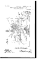
- Figure 1 1s aside elevation of a bale-forming machine constructed in accordance with the invention.
- Fig. 2 is a longitudinal sectional elevation of the same.
- Fig. 3 is an end elevation of the machine.
- Fig. 4 is a detail perspective view of one of the bale-cores.
- a substantial frame 10 which may be formed of either wooden beams orof structural iron.
- an inolined table 11 which receives the loose cotton or similar material to be baled.
- the lower portion of this table is provided with transversely-disposed slots, through which extend portions of the peripheries of compressionrollers 12, the opposite ends of which are in the form of shafts or 'gudgeons 13, that extend through suitable bearings formed in the frame and are provided at one or both sides with small gears 14:.
- the gears are connected in a practically continuous train by agear 15 to a main driving-gear l6, and the lowermost of the gears 14 intermeshes with a transmission-gear 17, that is mounted on suitable bearings in a strap fulcrumed on the shaft or gudgeon of the lowermost roller.
- rollers 12 Immediately above the rollers 12 are upper compression-rollers 20, the end shafts 0r gudgeons of which extend through suitable bearings carried by the frame.
- the upper halves of the bearing-boxes are held down by springs 21, and the stress of the springs may be adjusted by screws 22.
- the shafts or gudgeons of the upper rollers are provided with gears 24, arranged in a continuous train and so disposed that they may freely rise and fall in accordance with the thickness of the bat being formed. This train of gears is in mesh with the end gear 17 of the lower train.
- the frame is provided with bearings for the support of the shafts of three transverselyextending rollers 25, 27, and a lower roller 28, and over all of these rollers extends a belt 29, formed of leather, canvas, or other suitable material.
- the two upper rollers constitute a portion of the bale-forming means, while the shaft of the lower roller is provided with a belt-pulley 30 or a suitable gear, to which power may be transmitted in any desired man-
- the bearings of the rollers 28 are yieldable, the caps of the bearings being depressed by adjustable springs 31, that will allow some slight upward movement of the roller to permit variations in the diameter of the bale during the compressing operation.
- a slidable frame 35 In the opposite sides of the frame are guideways 34 for the reception of the side bars of a slidable frame 35, that is provided with transversely-disposed brace-bars 36 and 37.
- a shaft 38 At the forward end of the frame 35 are bearings for a shaft 38, carrying a compressionroller 39 of comparatively large diameter and serving to coact with the rollers 25 27 and operating to form a bale.
- One or both ends of the shaft 38 is provided with sprocket-wheel 40, connected by a link belt 41 to a sprocketwheel 42, mounted on a shaft 43, held in suitable bearings in the frame.
- the shaft 43 is further provided with a gear 44, connected by a link belt with a gear 45 on the shaft of the lower roller 28.
- At one end of the frame are bearings for the support of a transversely-extending windingroller 48, around which are wound the ends of a pair of cables or chains 49, said end portions being rigidly secured to the roller.
- the opposite ends of said cables or chains are connected to the sides of the frame 35.
- Wrapped around the center of the roller 48 and secured thereto is one end of a cord or chain 50, carrying a heavy weight or spring, and said weight may be adjusted in accordance with the extent to which the cotton or other material is to be compressed, it being merely necessary to add or remove portions of the weight.
- afiuid-pressure cylinder 55 in which is arranged a suitable piston connected by a rod 56 to a cross-bar 57, and one end of the cross-bar has an opening 58 for the passage of the weighted cable 50, the walls of the opening being arranged at such an angle that the crossbar is held in position to bite into the cable or cord, this occurring at the end of each compression operation in order that the roller 39 may be relieved of the weight and the baling-chamber opened to permit the discharge of the bale.
- a hook 59 To the opposite end of the cross-bar 57 is connected a hook 59, the lower end of which passes under a cross-bar 60.
- the cross-bar 60 is connected at its opposite ends to two angular frames 61, pivoted at 62 to the main frame and connected at their upper ends by pivot-bolts 63 to bars 64, said bars 64 being connected to the opposite ends of the shaft 38, the connections being such that when steam, air, or other fluid under pressure is admitted below the piston the cross-bar 57 will be raised, the weight elevated, and the frame 35 and compressing-roller moved outward from contact with the finished bale.
- the bales are wound on cores or spools 70, having enlarged end flanges 71 provided with projecting end disks 72. These cores or spools are placed in a hopper or chute 7 3, and normally the end disk 72 of the lowermost core rests on spring-fingers 75, arranged at the lower ends of a pair of arms 76.
- the arms 76 are pivotall y connected at their upper ends to the upper ends of levers 77, that are pivoted at 78 to the frame, and the lower ends of said levers extend between the two cross-bars 36 and 37 of the slidable frame 35.
- cushioning-springs 79 To the rear of the levers are arranged cushioning-springs 79, which form back-stops for limiting the rearward movement of said levers.
- inclined slots or grooves 80 of a width sufficient to receive the end disks 72 of the cores, and when the arms 76 are forced downward the lowermost core is forced down into the grooves 80 and finally rests on the lower wall of the guideway 34 at a point between the belt 29 and the main compressionroller 39, or, in other words, is placed in the baling-chamber.
- the inner walls ofthe frame are provided with grooves 81, extending from the lower walls of the guideways 34 and of a width sufficient to receive the disk 72, and in discharging the disks pass through the grooves 81 and fall onto inclined bars 82, down which they roll, carrying the compressed bale to other portions of the machine, where the bale is wrapped and tied.
- the cylinder 55 herein referred to is connected by a pipe 84 to a suitable source of pressure-supply, and in said pipe is a valve 85, that is connected by a link 86 to one end of a lever 87, that is pivoted at a point intermediate of its length to the frame.
- the opposite end of the lever 87 is connected to a rod 88, that in turn is connected to the lower end of a small lever 89, pivoted at a point intermediate of its length to the frame.
- the upper end of the lever 89 is connected to an arm 90, that is disposed in the path of movement of a lug or pin 91, projecting from one side of the frame 35, and the lug serves to engage this arm during the outward movement of the frame in order to transmit movement to the valve.
- the rod 88 is provided with a shoulder 92, that normally rests in engagement with a stop 93, projecting from the frame,
- a spring 94 the opposite end of which is carried by a pin 95.
- the function of the spring is to hold the shoulder in engagement with the stop 93, and in this position of the parts the valve is held closed.
- the rod 88 is slotted for the passage of a bolt 96, carrying a cam 97, which may be adjusted to any desired point in the length of the rod.
- the frame 35 carries a finger 98 for engagement with the cam as the frame and compression-roller move outward, and when this occurs the rod 88 is moved downward until the shoulder 92 is free from the stop 93, whereupon the spring 94 pulls the rod to the left and opens the valve 85.
- the loose cotton passing down the table 11 is compressed between the three sets of rollers 12 20, and by proper adjustment of the screws 22 the pressure at first may be slight and afterward increased, so that the bat will be tightly compressed when it issues fromthe final rollers.
- the bat then passes between the compression-roller 39 and the core, and as the opposite side of the spool or core is engaged by the belt 29 it will be rotated in such manner as to gradually wind the bat thereon.
- the bat will be compressed into the form of a bale, owing to the weight 51, and the pressure of the belt 29 Will gradually alter as the diameter of the bale increases. In all cases, however, the pressure will be uniform and regular, and the bale in process of formation will act as a friction-roller for transmitting movement from the belt to the roller 39, and this is utilized in the driving of other portions of the machine, as hereinafter described.
- a belt, atransfer-roller serving as a bale-forming means, and means for imparting movement to the belt, the bale being formed serving as a friction member for transmitting movement from the belt to the roller.
- a compression means and means under the control of the bale being formed for automatically moving the compression means to inoperative position when said bale has reached a predetermined size.
- a compression-roller In a baling-press, a compression-roller, means for automatically moving the roller to inoperative position, and means for adjusting the time of operation in accordance with the diameter of the bale to be formed.
- a baling-press a compression-roller, amovable frame supporting the roller, means for moving the roller out of contact with the bale, and mechanism operable by the movement of the frame for controlling the operation of the roller-moving means.
- valve-operating rods disposed in the path of movement of said frame.
- baling-machine having a baling-chamber, of a pair of compression members, means for automatically feeding empty cores or spools to the compression-chamber, and means for automatically discharging completed bales from said chamber.
- baling-machine the combination with compression members, of a frame having grooves leading between said compression members, and means for feeding cores or spools along said grooves.
Landscapes
- Engineering & Computer Science (AREA)
- Mechanical Engineering (AREA)
- Preliminary Treatment Of Fibers (AREA)
Description
No. 809,283. PATENTED JAN. 9, 1906. c. M. OAGLE. MACHINE FOR FORMING ROUND COTTON BALES.
APPLIGATION FILED JAN. 31. 1905.
3 SHEETS-SHEET 1. "w
Inventor.
Witnesses Httomegs No. 809,283. PATENTED JAN. 9, 1906.
-- 0. M. OAGLE.
MACHINE POR'PORMING ROUND COTTON BALES APPLICATION FILED JAN. 31, 1905.
3SHEETS-SHEET Z.
648%? Cagle,
Witnesses Inventor,
PATBNTED JAN. 9, 1906.
s SHEETSSHEET s.
0. M. GAGLB.
APPLICATION FILED JAN. 31, 1905.
MACHINE FOR FORMING ROUND COTTON BALES.
Q56 Q? s Inventor, W
Httomegs UNITED STATES CARTER M. (JAGLE, OF BECKVILLE, TEXAS.
MACHINE FOR FORMING ROUND COTTON-BALES.
Specification of Letters Patent.
Patented Jan. 9, 1906.
Application filed January 31, 1905. Serial No. 243,537.
To all whom it may concern.-
Be it known thatl, CARTER M. CAeLE, acitizen of the United States, residing at Beokville.
in the county of Panola and State of Texas, have invented a new and useful Machine for Forming Round Cotton-Bales, of which the following is a specification.
This invention relates to baling-presses, and more particularly to presses of that type employed in the production of cylindrical cottonbalcs.
The principal object of the invention is to providea machine of the most simple construction in which the cotton is received from the condenser or other source of supply and is first formed into a bat and thence gradually rolled until it forms a bale of any predetermined diameter, a further object in this connection being to provide means whereby when the bale has reached the desired size it will be automatically discharged from the balingchamber.
A further object of the invention is to provide a novel formof bale-discharging means which may be quickly adjusted to provide for the automatic discharge of the bales when they have assumed the diameter required by such adjustment.
A still further object of the invention is to provide a bale-rolling machine in which provision is made for the automatic feeding of bale-cores to the baling-chamber immediately after the discharge of a complete bale.
A still further object of the invention is to provide a round bale-forming machine in which the operation of the parts will be continuous, it being unnecessary to stop the feeding of the cotton or the feeding of the bat between the bale-forming intervals.
With these and other objects in view, as will more fully hereinafter appear, the invention consists in certain novel features of. construction and arrangement of parts hereinafter fully described, illustrated in the accompanying drawings, and particularly pointed out in the appended claims, it being understood that various changes in the form, proportions, size, and minor details of the structure may be made without departing from the spirit or sacrificing any of the advantages of the invention.
In the accompanying drawings, Figure 1 1s aside elevation of a bale-forming machine constructed in accordance with the invention. Fig. 2 is a longitudinal sectional elevation of the same. Fig. 3 is an end elevation of the machine. Fig. 4: is a detail perspective view of one of the bale-cores.
Similar numerals of reference are employed to indicate corresponding parts throughout the several figures of the drawings.
The various working parts of the apparatus are supported on a substantial frame 10, which may be formed of either wooden beams orof structural iron.
At the upper portion of the frame is an inolined table 11. which receives the loose cotton or similar material to be baled. The lower portion of this table is provided with transversely-disposed slots, through which extend portions of the peripheries of compressionrollers 12, the opposite ends of which are in the form of shafts or 'gudgeons 13, that extend through suitable bearings formed in the frame and are provided at one or both sides with small gears 14:. The gears are connected in a practically continuous train by agear 15 to a main driving-gear l6, and the lowermost of the gears 14 intermeshes with a transmission-gear 17, that is mounted on suitable bearings in a strap fulcrumed on the shaft or gudgeon of the lowermost roller.
Immediately above the rollers 12 are upper compression-rollers 20, the end shafts 0r gudgeons of which extend through suitable bearings carried by the frame. The upper halves of the bearing-boxes are held down by springs 21, and the stress of the springs may be adjusted by screws 22. The shafts or gudgeons of the upper rollers are provided with gears 24, arranged in a continuous train and so disposed that they may freely rise and fall in accordance with the thickness of the bat being formed. This train of gears is in mesh with the end gear 17 of the lower train.
The frame is provided with bearings for the support of the shafts of three transverselyextending rollers 25, 27, and a lower roller 28, and over all of these rollers extends a belt 29, formed of leather, canvas, or other suitable material. The two upper rollers constitute a portion of the bale-forming means, while the shaft of the lower roller is provided with a belt-pulley 30 or a suitable gear, to which power may be transmitted in any desired man- The bearings of the rollers 28 are yieldable, the caps of the bearings being depressed by adjustable springs 31, that will allow some slight upward movement of the roller to permit variations in the diameter of the bale during the compressing operation.
In the opposite sides of the frame are guideways 34 for the reception of the side bars of a slidable frame 35, that is provided with transversely-disposed brace-bars 36 and 37. At the forward end of the frame 35 are bearings for a shaft 38, carrying a compressionroller 39 of comparatively large diameter and serving to coact with the rollers 25 27 and operating to form a bale. One or both ends of the shaft 38 is provided with sprocket-wheel 40, connected by a link belt 41 to a sprocketwheel 42, mounted on a shaft 43, held in suitable bearings in the frame. The shaft 43 is further provided with a gear 44, connected by a link belt with a gear 45 on the shaft of the lower roller 28.
At one end of the frame are bearings for the support of a transversely-extending windingroller 48, around which are wound the ends of a pair of cables or chains 49, said end portions being rigidly secured to the roller. The opposite ends of said cables or chains are connected to the sides of the frame 35. Wrapped around the center of the roller 48 and secured thereto is one end of a cord or chain 50, carrying a heavy weight or spring, and said weight may be adjusted in accordance with the extent to which the cotton or other material is to be compressed, it being merely necessary to add or remove portions of the weight. At this end of the machine is afiuid-pressure cylinder 55, in which is arranged a suitable piston connected by a rod 56 to a cross-bar 57, and one end of the cross-bar has an opening 58 for the passage of the weighted cable 50, the walls of the opening being arranged at such an angle that the crossbar is held in position to bite into the cable or cord, this occurring at the end of each compression operation in order that the roller 39 may be relieved of the weight and the baling-chamber opened to permit the discharge of the bale. To the opposite end of the cross-bar 57 is connected a hook 59, the lower end of which passes under a cross-bar 60. The cross-bar 60 is connected at its opposite ends to two angular frames 61, pivoted at 62 to the main frame and connected at their upper ends by pivot-bolts 63 to bars 64, said bars 64 being connected to the opposite ends of the shaft 38, the connections being such that when steam, air, or other fluid under pressure is admitted below the piston the cross-bar 57 will be raised, the weight elevated, and the frame 35 and compressing-roller moved outward from contact with the finished bale.
The bales are wound on cores or spools 70, having enlarged end flanges 71 provided with projecting end disks 72. These cores or spools are placed in a hopper or chute 7 3, and normally the end disk 72 of the lowermost core rests on spring-fingers 75, arranged at the lower ends of a pair of arms 76.
The arms 76 are pivotall y connected at their upper ends to the upper ends of levers 77, that are pivoted at 78 to the frame, and the lower ends of said levers extend between the two cross-bars 36 and 37 of the slidable frame 35. To the rear of the levers are arranged cushioning-springs 79, which form back-stops for limiting the rearward movement of said levers.
In the inner faces of the frame members are arranged inclined slots or grooves 80 of a width sufficient to receive the end disks 72 of the cores, and when the arms 76 are forced downward the lowermost core is forced down into the grooves 80 and finally rests on the lower wall of the guideway 34 at a point between the belt 29 and the main compressionroller 39, or, in other words, is placed in the baling-chamber. The inner walls ofthe frame are provided with grooves 81, extending from the lower walls of the guideways 34 and of a width sufficient to receive the disk 72, and in discharging the disks pass through the grooves 81 and fall onto inclined bars 82, down which they roll, carrying the compressed bale to other portions of the machine, where the bale is wrapped and tied.
The cylinder 55 herein referred to is connected by a pipe 84 to a suitable source of pressure-supply, and in said pipe is a valve 85, that is connected by a link 86 to one end of a lever 87, that is pivoted at a point intermediate of its length to the frame. The opposite end of the lever 87 is connected to a rod 88, that in turn is connected to the lower end of a small lever 89, pivoted at a point intermediate of its length to the frame. The upper end of the lever 89 is connected to an arm 90, that is disposed in the path of movement of a lug or pin 91, projecting from one side of the frame 35, and the lug serves to engage this arm during the outward movement of the frame in order to transmit movement to the valve. The rod 88 is provided with a shoulder 92, that normally rests in engagement with a stop 93, projecting from the frame,
and to the rod is secured one end of a spring 94, the opposite end of which is carried by a pin 95. The function of the spring is to hold the shoulder in engagement with the stop 93, and in this position of the parts the valve is held closed.
The rod 88 is slotted for the passage of a bolt 96, carrying a cam 97, which may be adjusted to any desired point in the length of the rod. The frame 35 carries a finger 98 for engagement with the cam as the frame and compression-roller move outward, and when this occurs the rod 88 is moved downward until the shoulder 92 is free from the stop 93, whereupon the spring 94 pulls the rod to the left and opens the valve 85.
' machine.
soasa In the operation of the machine a core or spool is first placed in the baling-chamber,
and the machine is then started. The loose cotton passing down the table 11 is compressed between the three sets of rollers 12 20, and by proper adjustment of the screws 22 the pressure at first may be slight and afterward increased, so that the bat will be tightly compressed when it issues fromthe final rollers. -The bat then passes between the compression-roller 39 and the core, and as the opposite side of the spool or core is engaged by the belt 29 it will be rotated in such manner as to gradually wind the bat thereon. During the winding operation the bat will be compressed into the form of a bale, owing to the weight 51, and the pressure of the belt 29 Will gradually alter as the diameter of the bale increases. In all cases, however, the pressure will be uniform and regular, and the bale in process of formation will act as a friction-roller for transmitting movement from the belt to the roller 39, and this is utilized in the driving of other portions of the machine, as hereinafter described.
As the bale nears completion the frame 35 in moving outward will force the finger 98 into contact with the. cams 97, and in moving over the cam the rod 88 will be depressed until the shoulder 92 is free from the stop 93. The spring 9 pulls on the rod 88, and the movement is transmitted to lever 87 and link 86 to the valve. When the valve is opened, air, steam, or other fluid under pressure enters the cylinder and elevates the piston therein. This movement is transmitted, through the cross-bar 57 to the hook 59, raising the outer portion of the frame 61, and as the latter swings on'its pivot 62 the movement is transmitted to the bars 64 and from thence to the frame 35, causing the latter to carry the compression-roller 39 outward from the bale at a comparatively rapid rate of speed. The pull on the hook-supporting end of the crossbar 57 causes the inner end of the latter to tilt upward, and the inclined walls of the opening 58 then grip the cable 50 and a portion of the pressure is utilized in raising the weight. IVhen the belt 29 is relieved from the pressure of the beltand the roller 39, the springs 31 tend to force the roller downward, and thus strengthen the forward side of the belt. This movement ejects the bale, and the disks 72 of the spool roll under the guideways 34 until the grooves 81 are reached, the bale then passing down on the skids or bars 82 to the wrapping and tying portions of the As the frame 35 moves to the rear the-bar 37 will engage the lower ends of the lever 7 7 and this movement is transmitted to the arm 7 6, causing the latter to feed another spool into the baling-chamber, so that the operation may be continued; Further movement of the frame 35 causes lug 91 to engage the bar 90, whereupon movement is transmitted through the lever 89, rod 88, lever 87,
and link. 86 to the valve, closing the pressuresupply port and opening the cylinder to an exhaust-pipe 100, so that the frame and compression-roller are free to move forward to operative position, and the operation of forming a fresh bale may be immediately commenced without stopping the feeding of the cotton or the formation of the bat.
Having thus described the invention, what is claimed is" 1. In a bale-forming machine,a belt, atransfer-roller serving as a bale-forming means, and means for imparting movement to the belt, the bale being formed serving as a friction member for transmitting movement from the belt to the roller.
2. In a baling-press, a compression means, and means under the control of the bale being formed for automatically moving the compression means to inoperative position when said bale has reached a predetermined size.
3. In a baling-press, a compression-roller, and means for automatically moving the same to inoperative position when the bale has reached a predetermined size.
4. In a baling-press, a compression-roller, means for automatically moving the roller to inoperative position, and means for adjusting the time of operation in accordance with the diameter of the bale to be formed.
5. In a baling-press, a compression-roller, amovable frame supporting the roller, means for moving the roller out of contact with the bale, and mechanism operable by the movement of the frame for controlling the operation of the roller-moving means.
6. The combination in a baling-press, of a compression-roller,a frame carrying the same, frame-engaging means for adjusting the roller to inoperative position, and an adjustable mechanism operable by the frame for controlling the operation of said frame-engaging means.
7. The combination in a baling-press, of a compressionroller,a frame carrying the same, a fluid-pressure-actuated mechanism for moving the roller to inoperative position, and means controlled by said frame for governing the supply of fluid under pressure to said mechanism.
8. The combination in a baling-press, of a compression-roller, a movable frame carrying said roller,a fluid-pressure-operated means for engaging said frame, and adjusting the rollers to inoperative position, a normally closed valve for governing the flow of fluid under pressure to said mechanism, and means operable by the frame for opening said valve.
9. The combination in a balingpress, of a compression-roller, a slidable frame for said roller, a fluid-pressure-operated mechanism for moving the roller to inoperative position,
a valve for controlling the flow of fluid under pressure to such mechanism, and valve-operating rods disposed in the path of movement of said frame.
10. The combination in a baling-press, of a compression-roller, a slidable frame carrying said compression-roller, a fluid-pressure-operated mechanism for moving the roller to inoperative position, a valve controlling the flow of fluid to said mechanism, a valve-operating rod having a locking-shoulder, a fixed stop for engaging the shoulder, a valve-opening spring engaging the rod, and adjustable means operable on movement of the frame for moving said shoulder from engagement with the stop.
11. The combination in a baling-press, of a compression-roller, a movable frame carrying said roller, a fluid pressure operated mechanism for moving said roller to inoperative position, a valve for controlling the flow of fluid under pressure to said mechanism, a valve-operating rod having a locl ing-shoulder, a fixed stop with which said shoulder engages, a spring engaging the rod and serving when the latter is released to move the valve to open position, an adjustable cam carried by the rod, and a lug or finger carried by the frame and adapted to engage said cam.
12. The combination in a baling-press, of a compression-roller, a movable frame carrying said roller, a fluid-pressure-operated means engaging said frame, a normally closed valve controlling the flow of fluid to and from said means, and valve-operating means carried by the frame.
13. The combination with a compressionroller, of a movable frame carrying said roller. a fluid-pressure-operated means engaging said frame, a valve for controlling the flow of fluid under pressure to and from said means, a valve-operating device, and means carried by the frame for engaging said device and first opening and then closing said valve.
14:. The combination in a baling-press, of a compression device, and means for automatically moving the same into and out of operative position.
15. The combination in a baling-press, of a compression means, means for automatically moving the same to inoperative position at the completion of each bale-forming operation, and mechanism for restoring the compression means to operative position after the discharge of a finished bale.
16. The combination in a baling-machine, of a compression-roller, a slidable frame carrying said roller, a weight connected to the frame and tending to hold the roller in engagement with the bale, a fluid-pressure cylinder, a piston in said cylinder, links forming aconnection between the piston and theframe, and means connecting the piston to the link to adjust the roller to inoperative position.
17. The combination in abaling-machine, of a compression-roller, a frame carrying the same, a Winding-drum, cables or chains connecting the frame to the drum, a weighted cable or chain secured to said frame, a rocking frame connected to the roller-carrying frame, a fluid-pressure cylinder, a piston arranged therein and connected to the rocking frame, a valve for controlling the flow of fluid under pressure to and from the cylinder, a rod connected to the valve and provided with a shoulder, a stop with which said shoulder engages, a spring connected to the rod, a cam on said rod, a lug or finger arranged on the movable frame and serving to engage said cam, an arm connected to the valve-rod, and a projecting lug carried by the frame and adapted to engage said arm as the roller-carrying frame nears the limit of its rearward movement.
18. The combination in a baling-press, of compression members, and means for automatically feeding cores or spools between said compression members.
19. The combination in a baling-machine having a baling-chamber, of a pair of compression members, means for automatically feeding empty cores or spools to the compression-chamber, and means for automatically discharging completed bales from said chamber.
20. In a baling-machine, the combination with compression members, of a frame having grooves leading between said compression members, and means for feeding cores or spools along said grooves.
21. The combination in a baling-machine, of grooved frames, means for feeding cores or spools along said grooves, and a compression member serving at the completion of'each baling operation to feed the filled core or spool to discharge position .in said grooves.
22. The combination in a baling-maehine, of a baling-chamber, compression members, a core or spool reservoir, and means for feeding single spools therefrom to the balingchamber.
23. The combination in a baling-press, of compression members forming a baling-chamher, a core or spool reservoir, and means under the control of one of said compression members for automatically feeding single cores or spools from the reservoir to the baling-chamber.
24:. The combination with a frame, of a compression-roller, a slidable carrier therefor, a core-feeding frame, and an arm secured to said frame and arranged in the path of movement of the carrier.
25. The combination in a baling-machine, of compression members forming a baling-chamher, a movable frame carrying one of said compression members, a core or spool reservoir, a rocking frame having one end in the path of movement of the movable frame, and yieldable fingers carried by the rocking frame and serving to engage successive cores as they are fed to the baling-chamber.
IIO
form of a cylindrical bale, means for automatically feeding fresh cores to the balingchamber, and means for automatically dischargingfillecl cores from said chamber.
In testimony that I claim the foregoing as my own 1 have hereto affixed my signature 1n IO the presence of two Witnesses.
CARTER M. OAGLE.
Witnesses:
E. T. CRAWFORD; B. H. NEIL.
Priority Applications (1)
| Application Number | Priority Date | Filing Date | Title |
|---|---|---|---|
| US24353705A US809283A (en) | 1905-01-31 | 1905-01-31 | Machine for forming round cotton-bales. |
Applications Claiming Priority (1)
| Application Number | Priority Date | Filing Date | Title |
|---|---|---|---|
| US24353705A US809283A (en) | 1905-01-31 | 1905-01-31 | Machine for forming round cotton-bales. |
Publications (1)
| Publication Number | Publication Date |
|---|---|
| US809283A true US809283A (en) | 1906-01-09 |
Family
ID=2877764
Family Applications (1)
| Application Number | Title | Priority Date | Filing Date |
|---|---|---|---|
| US24353705A Expired - Lifetime US809283A (en) | 1905-01-31 | 1905-01-31 | Machine for forming round cotton-bales. |
Country Status (1)
| Country | Link |
|---|---|
| US (1) | US809283A (en) |
-
1905
- 1905-01-31 US US24353705A patent/US809283A/en not_active Expired - Lifetime
Similar Documents
| Publication | Publication Date | Title |
|---|---|---|
| US4176596A (en) | Machine for forming a round bale of fibrous agricultural material | |
| US2336491A (en) | Rotary baler | |
| US4499714A (en) | Method of baling, and baling press | |
| US3722197A (en) | Method and machine for forming a large round bale of a fibrous material | |
| US4212149A (en) | Crop baling machines | |
| SU1743328A3 (en) | Baling press | |
| US4667592A (en) | Agricultural baler | |
| CN110884711A (en) | Trailed Smart Cotton Baler | |
| CA1212578A (en) | Method for unplugging cylindrical baler | |
| ITRM950505A1 (en) | ROUND BALER FOR COLLECTING AND FORMING CYLINDRICAL BALES OF FORAGE OR STRAW, OF THE VARIABLE CHAMBER TYPE, WITH CHAMBER | |
| US4288971A (en) | Round baler | |
| EP3593627A1 (en) | Constant tension mechanism of tying net for roll bales | |
| US963775A (en) | Baling mechanism. | |
| US809283A (en) | Machine for forming round cotton-bales. | |
| GB2128542A (en) | Baler for forming cylindrical bales | |
| US862105A (en) | Method of forming round bales. | |
| US1510885A (en) | Round-bale gin compress | |
| US798969A (en) | Machine for reeling edible fibrous material and grain. | |
| US20200015423A1 (en) | Roll bales tying material feeding mechanism | |
| US614186A (en) | Ments | |
| US400912A (en) | Baling-press | |
| US1069112A (en) | Hay-baling machine. | |
| US851131A (en) | Baling-press. | |
| US660243A (en) | Cotton-press. | |
| US1227761A (en) | Hay-press. |