US809268A - Sparking ignition system. - Google Patents
Sparking ignition system. Download PDFInfo
- Publication number
- US809268A US809268A US23316504A US1904233165A US809268A US 809268 A US809268 A US 809268A US 23316504 A US23316504 A US 23316504A US 1904233165 A US1904233165 A US 1904233165A US 809268 A US809268 A US 809268A
- Authority
- US
- United States
- Prior art keywords
- breaker
- inductor
- circuit
- frame
- stator
- Prior art date
- Legal status (The legal status is an assumption and is not a legal conclusion. Google has not performed a legal analysis and makes no representation as to the accuracy of the status listed.)
- Expired - Lifetime
Links
Images
Classifications
-
- H—ELECTRICITY
- H02—GENERATION; CONVERSION OR DISTRIBUTION OF ELECTRIC POWER
- H02K—DYNAMO-ELECTRIC MACHINES
- H02K21/00—Synchronous motors having permanent magnets; Synchronous generators having permanent magnets
- H02K21/38—Synchronous motors having permanent magnets; Synchronous generators having permanent magnets with rotating flux distributors, and armatures and magnets both stationary
Definitions
- My invention relates to apparatus for the generation of high-tension sparks suitable for the efficient ignition of explosive mixtures.
- One object of the invention is to design a single-phase generator to deliver periodically an alternating current having suflicient energy for the desired purpose, the relation between the stator and the rotor being such that the time of generation of the alternating current may be varied at will.
- a further object of the invention is to combine with such generator a circuit-breaker so mounted with relation to the stator as that they shall always occupy the same relative positions however adjusted in order to secure at all times coincidence between the period of maximum intensity of the current and the time of breaking of the circuit to obtain in a transformer a high-tension spark suitablefor ignition purposes.
- the alternating-current generator used by me belongs to the type known as inductor-alternators, in which type the moving element may be an iron inductor modifying by its rotation the distribution of the magnetic flux through the stationary coils, whereby alternating electromotive forces are set up in the coils.
- I mount the stator of the generator with such relation to the rotor that the former is capable of rotary adjustment at will, either by hand or automat-ically, so that the time of current generation is made to depend upon the relative angular positions between the magnetic axis of the coil and the polar projection on the inductor.
- I rigidly secure to the stator of the generator a circuit-breaker and operate said breaker positively and automatically by a camon the inductor so placed as to break the circuit at or near the time when the alternating current reaches its maximum intensity.
- the function of said breaker is to short-circuit the alternating current on its own circuit at or near its maximum and to suddenly open the circuit, so as to throw the energy accumulated in the form of self-induction in the primary of an induction coil shunted by a condenser of determined condensence, so that part of the energy of the current generated shall appear in the spark taking place across the terminals of the secondary of the induction-coil.
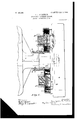
- FIG. 1 is a top view, certain of the parts being shown in section along the plane of the line 1 1 of Fig. 3.
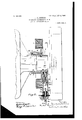
- Fig. 2 is aside view with certain of the parts shown in section on the plane of the line 2 2 of Fig. 3.
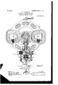
- Fig. 3 is a front view with the inductor removed and the breaker in section on the plane of the line 3 3 of Fig. 2 and also showing the circuit dia grammatically, and
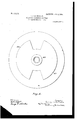
- Fig. 4 is a face view of the inductor.
- the numeral 1 designates a portion of the crank-casing of an internal-combustion engine, said casing having a bearing for the motor-shaft 2.
- the end of the casing 1 is formed with a hub 3, and keyed to said hub is a sleeve 4, having an outwardly-turned flange 5, said sleeve constituting a bearing for a frame 6, preferably made of non-magnetic material and constructed, as shown, to support the field -magnet 7 and breaker 20, as hereinafter more fully described.
- inductor or rotor of the generator therefore rotates at the same speed as the motorshaft, or it may be so connected by gearing or other suitable means to rotate at a multiple of the speed of the motor-shaft.
- a thrust-washer 9 bears against the flange 5, and bolts 10, having lock-nuts 11, bearing against said washer, pass through said washer and the frame 6 to maintain the latter against longitudinal movement toward or away from the inductor, the construction permitting, however, rotary movement of said frame and the magnet and breaker carried thereby about the sleeve A, such rotary adjustment being effected through a lever 12, secured to an extension 13 of said frame and operated either by hand or automatically at will.
- the field-magnet 7 supported by the frame 6, is an annular permanent magnet constructed in accordance with my application, Serial No. 229,310, filed October 20, 1904. P*ieiiy stated, it is formed of a steel ribbon continuously Wound in the form of a helix after it has been hardened, suitable insulating material being interposed between adjacent convolutions of the ring. After the steel ring has been securely fastened to the frame 6 it is accurately ground at two opposite Zones of the same diameter and placed in a powerful magnetic circuit, closing itself about the two Zones and about each side vof the magnet to develop two opposite magnetic poles.
- Two annular segments 14, constituting polar projections, are securely fastened to the two opposite zones by bolts 15, care being taken that said segments fit perfectly over the whole surface of the zones in order to reduce the reluctance of the magnetic joint to a minimum.
- the polar projections 11 are slotted, as shown in Fig. 1, in order to prevent closed-circuited currents around the edges of said projections.
- Coils 16 are wound on the polar projections 14.
- the polar projections 14 are insulated both electrically and mechanically from the frame, and the inside terminals of the coils 16 are grounded in the frame, the outside terminal of said coils being connected in parallel with the primary of an induction-coil, and in order to completely protect the coils 16 they are surrounded, as shown in Fig. 1, by a filling 18, of waterproof material.
- fly-wheel 8 of the motor to serve as an inductor
- any disk of suitable material would answer the same purpose, inasmuch as its function consists mainly in permitting the magnetic lield concentrated, respectively, about the poles 14 to close its circuit through the polar projections 19 on the inductor and the central mass of the inductor.
- the utilization of the fly-wheel as an inductor presents a compact form of generator.
- the inductor 8 is so mounted on the shaft 2 as to rotate in close proximity to the polar projections of the field-magnet, (about one sixty-fourth of an inch,) suitable means being provided to prevent any side motion of the inductor.
- Fig. 3 the circuit is diagrammatically shown.
- the outside terminals of the coils 16 are connected in parallel to one of the terminals of the primary of the induction-coil and the inside terminals of the coils 16 are grounded on the frame, as well as the other terminal of the primary.
- the secondary 51 of the induction-coil is grounded in mass, the other terminal being connected to the jump-spark plug 23.
- a condenser 2 L having a condensence equal to the reactance of the primary, is connected to one terminal of the primary and to ground.
- the breaker now to be described, is connected across the terminals of the primary of the inductioncoil.
- the breaker (shown in detail in Fig. 3) is inclosed within a casing 20, having a flanged head 25, adapted to fit snugly into an opening in the frame 6.
- the easing 20 is closed by a plug 26, having a head 27 threaded thereinto, said head being provided with a concave seatll to receive the end of a screw 28, the latter passing through a yoke 30.
- the screw 28 By turning up the screw 28 the breaker-casing 20 will be held firmly in position in its seat in the frame 6, the flange of the head 25 bearing against the outer wall of said frame, a pin 50, inserted in the frame 6, servingas aguide.
- the breaker-casing 20 may be held to its seat in the frame 6 by an eccentric or other suitable form of clamp.
- the casing 20 is provided with a chamber 31, in which the breaker-terminals 32 and 33 are supported, said chamber being filled with a non-volatile liquid, preferably glycerin, to prevent oxidation and consequent burning of the terminals.
- a non-volatile liquid preferably glycerin
- the breaker proper comprises two terminals 32 and 33, formed, preferably, of hardened nickel-steel.
- the lower terminal 33 is secured to a U-shaped head on one end of a plunger 36, extending upwardly through a chamber in the upper part of the casing 20.
- the upper terminal 32 is likewise secured to a U-shaped head on one end of a post 37, maintained in fixed position in the plug 26 by means of a lock-nut 38, suitable insulation 29 being interposed between said post and plug.
- the two terminals are held normally in contact with each other within the chamber 31 by a spring 34, surrounding the plunger 36 and held between a shoulder or ring 35, secured to the inner wall of the casing 20, and a shoulder on said plunger, said spring exerting. an upward tendency on said plunger.
- the plunger 36 has free vertical movement in they upper part of the casing 20 and is provided with a steel head 40, which normally projects through the opening in frame 6 and into the path of a cam 41, forming part of or attached to the hub 42 of the rotating inductor 8, the function of said cam being to depress the plunger 36 against the stress of spring 34, and thereby cause a sudden break in the circuit by separating the terminals 32 and 33 once for each revolution of the inductor, the said cam being so positioned as to cause a break in the current-circuit at or near the time when the current is at its maximum intensity.
- the cam 41 wipes from off the head 40 the plunger 36 will be moved by the spring 34 to close the circuit through the two terminals. This closing of the circuit takes place at a definite time.
- the breaker should be readily accessible and easily removed from the frame 6 without interfering with the circuit connections.
- I have devised a simple means. (Shown in Fig. 3.)
- the breaker is maintained in position by means of the screw 28 bearing against the head 27, the yoke 30 being supported upon two arms 44.
- the frame 6 has two lugs 45 formed thereon, through which pass screw-pins 46, terminating in a suitable insulating-ring 47.
- the arms 44 are screwed into the insulating-ring 47, said arms being maintained in their relative positions separated from the screw-pins 46 by means of heads 48 bearing against the outer arms of the yoke 30.
- a ring 49 surrounds the insulating-ring 47 to strengthen it.
- the arms 44 and screw pins 46 are separated from each other, as shown in Fig. 3.
- the yoke 30 is pivoted upon the right-hand arm 44, so as to swing thereon as a center, the left-hand end of said yoke having a notch to engage the other arm 44.
- By withdrawing the screw 28 from its seat in the head 27 the yoke 30 is free to be swung to one side, when the entire breaker may be moved from its socket in the frame 6.
- the coils 16 are in parallel and one terminal of said coils is connected to either or both of the arms 44.
- a sparking ignition system comprising an alternating-current generator of the inductor type, said generator consisting of astator having a field-magnet in the form of a permanently-magnetized ring Wound from a continuous steel ribbon, symmetrically-located polar projections secured to said ring, coils wound on said polar projections, an inductor mounted on a revoluble shaft whose axis is coincident with the axis of said stator and co nstituting a rotor, a circuit-breaker rigidly secured to said stator, a cam mounted on the rotor-shaft and adapted to actuate said breaker at the period of maximum current generation, a transformer, sparking electrodes included in the secondary circuit of the transformer, and means for shifting said stator and breaker relative to said rotor and cam respectively so as to modify at will the time of sparking.
- a sparking ignition system comprising an alternating-current generator of the inductor type, said generator consisting of a stator having a field-magnet in the form of a permanently-magnetized ring wound from a continuous steel ribbon, symmetrically-located polar projections secured to said ring, coils wound on said polar projections, an inductor mounted on a revoluble shaft whose axis is coincident with the axis of said stator and con- 1 stituting a rotor, a circuit-breaker rigidly secured to said stator, said breaker comprising a chambered casing filled with a non-volatile electrically-non-conductive liquid, terminals supported in said liquid, one of said terminals being fixed in position and insulated from the casing, a movably-supported plunger to which the other terminal is secured, a cam mounted on the rotor-shaft and adapted to actuate said breaker at the period of maximum current generatioma transformer, sparking electrodes included in
- an alternatingcurrent generator comprising a rotor and a stator, a supporting-frame for said stator, a circuit-breaker seated in an opening in said frame, a yoke carried by the frame and a clamp supported by said yoke and adapted to bear against the head of the breaker to force it to its seat.
- an alternatingcurrent generator comprising a rotor and a stator, a supporting-frame for said stator, a circuit-breaker seated in an opening in said frame, a yoke pivotally carried by said frame and a clamp supported by said yoke and adapted to bear against said breaker to force it to its seat.
Landscapes
- Engineering & Computer Science (AREA)
- Power Engineering (AREA)
- Ignition Installations For Internal Combustion Engines (AREA)
Description
4 SHEETS-SHEET 1.
PATBNTED JAN. 2, 1906.
L. J. LE PONTOIS. SPARKING IGNITION SYSTEM.
APPLIOATION FILED NOV 17,1904
No. 809,268. PATENTED JAN. 2, 1906. L. J. LE PONTOIS. SPARKING IGNITION SYSTEM.
APPLIOATION FILED NOV. 17,1904.
4 SHEETS-SHEET 2.
PATENTED JAN. 2, 1906.
L. J. LE PONTOIS.
SPARKING IGNITION SYSTEM.
urmouxon rum) NOV. 17,1904.
4 SHEETS-SHEET 3.
NO- 809,268 PATENTED JAN. 2, 1906.
L. J. LE PONTOIS.
SPARKING IGNITION SYSTEM.
APPLICATION FILED NOV.17,1904.
4 SHEETS-SHEET 4.
win-Manama gwug vt $31.3 elite buc UNITED STATE PATENT OFFICE.
LEON JULES LE PONTOIS, OF NEW ROCHELLE, NEW YORK, ASSIGNOR TO POLY-PHASE IGNITION SYSTEM COMPANY, A CORPORATION OF NEW YORK.
SPARKING IGNITION SYSTEM.
Patented Jan. 2, 1906.
Application filed November 17, 1904. Serial No. 233,165.
To all whom it may concern:
Be itknown that I, LEON JULnsLn PONTOIS, acitizen of the Republic of France, and a resident of New Rochelle, WVestchester county, New York, have invented a certain new and useful Improvement in Sparking Ignition Systems, of which the following is a specification.
My invention relates to apparatus for the generation of high-tension sparks suitable for the efficient ignition of explosive mixtures.
One object of the invention is to design a single-phase generator to deliver periodically an alternating current having suflicient energy for the desired purpose, the relation between the stator and the rotor being such that the time of generation of the alternating current may be varied at will.
A further object of the invention is to combine with such generator a circuit-breaker so mounted with relation to the stator as that they shall always occupy the same relative positions however adjusted in order to secure at all times coincidence between the period of maximum intensity of the current and the time of breaking of the circuit to obtain in a transformer a high-tension spark suitablefor ignition purposes.
Generally speaking, the alternating-current generator used by me belongs to the type known as inductor-alternators, in which type the moving element may be an iron inductor modifying by its rotation the distribution of the magnetic flux through the stationary coils, whereby alternating electromotive forces are set up in the coils.
In carrying out my invention I mount the stator of the generator with such relation to the rotor that the former is capable of rotary adjustment at will, either by hand or automat-ically, so that the time of current generation is made to depend upon the relative angular positions between the magnetic axis of the coil and the polar projection on the inductor. In order to secure the coincidence above referred to, I rigidly secure to the stator of the generator a circuit-breaker and operate said breaker positively and automatically by a camon the inductor so placed as to break the circuit at or near the time when the alternating current reaches its maximum intensity. By securing and maintaining the stator and breaker in fixed relation to each other it follows that whatever he the angular position of the stator relative to the rotor the time of operation of the breaker will always coincide with the time when the current reaches its maximum intensity. As a change in the time of sparking is required for the efficient working of internal-combustion engines running at variable speeds, I am enabled by the present invention to obtain any range of sparking by simply shifting the stator and its attached breaker on their common axis. It may be stated here that the function of said breaker is to short-circuit the alternating current on its own circuit at or near its maximum and to suddenly open the circuit, so as to throw the energy accumulated in the form of self-induction in the primary of an induction coil shunted by a condenser of determined condensence, so that part of the energy of the current generated shall appear in the spark taking place across the terminals of the secondary of the induction-coil. To prevent oxidation or deterioration of the contact-points of the breaker, due to inevitable arcing, notwithstanding the presence of the condenser across the gap, I inclose the breaker-terminals in a bath of non-volatile liquid, preferably glycerin.
I am aware that it is not new in the art to break currents in an oil-bath; but I believe that the idea of utilizing a glycerin-bath in connection with an apparatus of the type herein described to be new and original.
The invention will be understood by reference to the accompanying drawings, which illustrate one embodiment thereof, and in which- Figure 1 is a top view, certain of the parts being shown in section along the plane of the line 1 1 of Fig. 3. Fig. 2 is aside view with certain of the parts shown in section on the plane of the line 2 2 of Fig. 3. Fig. 3 is a front view with the inductor removed and the breaker in section on the plane of the line 3 3 of Fig. 2 and also showing the circuit dia grammatically, and Fig. 4 is a face view of the inductor.
Similar reference-numeralsindicate similar parts in the several views.
Referring to the drawings, the numeral 1 designates a portion of the crank-casing of an internal-combustion engine, said casing having a bearing for the motor-shaft 2. The end of the casing 1 is formed with a hub 3, and keyed to said hub isa sleeve 4, having an outwardly-turned flange 5, said sleeve constituting a bearing for a frame 6, preferably made of non-magnetic material and constructed, as shown, to support the field -magnet 7 and breaker 20, as hereinafter more fully described.
8 designates the flywheel of the motor,
.more mounted on shaft 2, and for convenience I have selected it to serve as an inductor, 19 designating two polar projections thereon. The inductor or rotor of the generator therefore rotates at the same speed as the motorshaft, or it may be so connected by gearing or other suitable means to rotate at a multiple of the speed of the motor-shaft.
A thrust-washer 9 bears against the flange 5, and bolts 10, having lock-nuts 11, bearing against said washer, pass through said washer and the frame 6 to maintain the latter against longitudinal movement toward or away from the inductor, the construction permitting, however, rotary movement of said frame and the magnet and breaker carried thereby about the sleeve A, such rotary adjustment being effected through a lever 12, secured to an extension 13 of said frame and operated either by hand or automatically at will.
The field-magnet 7 supported by the frame 6, is an annular permanent magnet constructed in accordance with my application, Serial No. 229,310, filed October 20, 1904. P*ieiiy stated, it is formed of a steel ribbon continuously Wound in the form of a helix after it has been hardened, suitable insulating material being interposed between adjacent convolutions of the ring. After the steel ring has been securely fastened to the frame 6 it is accurately ground at two opposite Zones of the same diameter and placed in a powerful magnetic circuit, closing itself about the two Zones and about each side vof the magnet to develop two opposite magnetic poles. Two annular segments 14, constituting polar projections, are securely fastened to the two opposite zones by bolts 15, care being taken that said segments fit perfectly over the whole surface of the zones in order to reduce the reluctance of the magnetic joint to a minimum. The polar projections 11 are slotted, as shown in Fig. 1, in order to prevent closed-circuited currents around the edges of said projections. Coils 16 are wound on the polar projections 14. The polar projections 14 are insulated both electrically and mechanically from the frame, and the inside terminals of the coils 16 are grounded in the frame, the outside terminal of said coils being connected in parallel with the primary of an induction-coil, and in order to completely protect the coils 16 they are surrounded, as shown in Fig. 1, by a filling 18, of waterproof material.
Although I have for the purpose of illustration selected the fly-wheel 8 of the motor to serve as an inductor, it is obvious that any disk of suitable material would answer the same purpose, inasmuch as its function consists mainly in permitting the magnetic lield concentrated, respectively, about the poles 14 to close its circuit through the polar projections 19 on the inductor and the central mass of the inductor. However, the utilization of the fly-wheel as an inductor presents a compact form of generator. The inductor 8 is so mounted on the shaft 2 as to rotate in close proximity to the polar projections of the field-magnet, (about one sixty-fourth of an inch,) suitable means being provided to prevent any side motion of the inductor. It has been found preferable to connect the coils 16 in parallel, grounding one terminal of their convolutions in order to secure a better insulation for their combined circuits. As the inductor is rotated it will cause variations in the intensity of the magnetic flux threading through the coils 16, and they will become the seats of alternating currents. Although it would be feasible to use a single coil, I prefer to use two coils in order to equalize the magnetic pull exerted by the poles of the inductor, as the pull exerted individually by each pole is modified by the current flowing through the coils surrounding it.
In Fig. 3 the circuit is diagrammatically shown. The outside terminals of the coils 16 are connected in parallel to one of the terminals of the primary of the induction-coil and the inside terminals of the coils 16 are grounded on the frame, as well as the other terminal of the primary. The secondary 51 of the induction-coil is grounded in mass, the other terminal being connected to the jump-spark plug 23. A condenser 2 L, having a condensence equal to the reactance of the primary, is connected to one terminal of the primary and to ground. The breaker, now to be described, is connected across the terminals of the primary of the inductioncoil.
The breaker (shown in detail in Fig. 3) is inclosed within a casing 20, having a flanged head 25, adapted to fit snugly into an opening in the frame 6. At its outer end the easing 20 is closed by a plug 26, having a head 27 threaded thereinto, said head being provided with a concave seatll to receive the end of a screw 28, the latter passing through a yoke 30. By turning up the screw 28 the breaker-casing 20 will be held firmly in position in its seat in the frame 6, the flange of the head 25 bearing against the outer wall of said frame, a pin 50, inserted in the frame 6, servingas aguide. Instead of using a screw the breaker-casing 20 may be held to its seat in the frame 6 by an eccentric or other suitable form of clamp. The casing 20 is provided with a chamber 31, in which the breaker-terminals 32 and 33 are supported, said chamber being filled with a non-volatile liquid, preferably glycerin, to prevent oxidation and consequent burning of the terminals. The glycerin-bath prevents the formation of an are,
JIO
which would be practically a continuation of the short circuit and deprive the primary circuit of the induction-coil of a large amount of energy of self-induction which should be wholly delivered to the primary circuit of the induction-coil.
The breaker proper comprises two terminals 32 and 33, formed, preferably, of hardened nickel-steel. The lower terminal 33 is secured to a U-shaped head on one end of a plunger 36, extending upwardly through a chamber in the upper part of the casing 20. The upper terminal 32 is likewise secured to a U-shaped head on one end of a post 37, maintained in fixed position in the plug 26 by means of a lock-nut 38, suitable insulation 29 being interposed between said post and plug. The two terminals are held normally in contact with each other within the chamber 31 by a spring 34, surrounding the plunger 36 and held between a shoulder or ring 35, secured to the inner wall of the casing 20, and a shoulder on said plunger, said spring exerting. an upward tendency on said plunger. The plunger 36 has free vertical movement in they upper part of the casing 20 and is provided with a steel head 40, which normally projects through the opening in frame 6 and into the path of a cam 41, forming part of or attached to the hub 42 of the rotating inductor 8, the function of said cam being to depress the plunger 36 against the stress of spring 34, and thereby cause a sudden break in the circuit by separating the terminals 32 and 33 once for each revolution of the inductor, the said cam being so positioned as to cause a break in the current-circuit at or near the time when the current is at its maximum intensity. As the cam 41 wipes from off the head 40 the plunger 36 will be moved by the spring 34 to close the circuit through the two terminals. This closing of the circuit takes place at a definite time. It is well known that in generators of this class the alternating current has a magnetizing and demagnetizing influence on the magnetic field. Under normal conditions that is, when the current does not manifest a reactance or a condensence in its circuitboth the magnetizing and demagnetizing actions are sensibly equal and the density of the magnetic field, if it be a permanent field, is practically unaltered. Taking advantage of these facts, I utilize for the operation of the induction-coil the current-wave obtained at the time when the inductor leaves the polar projections of the field, which, according to the law of Lenz, tends to oppose the decrease in the magnetic flux threading through the generator-coil. The demagnetizing action on the field by the other currentwave generated when the inductor approaches or covers the polar projections is, however, very slight, owing to the fact that the generating-coils 16 are in series with the primary 43 of the induction-coil and that the combined reactance of the circuits is suficient to prevent the current from reaching a harmful value. It can thus be seen that the action of the alternating current on the density of the magnetic fieldfthat is, on the life of the magnet tends to maintain the magnetic field in its normal degree of permanent magnetization. I have even observed that under such conditions the permanent magnetic field becomes strengthened. I therefore make the length of the cam 41 sufficient to maintain the circuit open while a demagnetizing current-wave occurs;
Inasmuch as the magnet 7 and the breaker are rigidly secured to the frame 6, the same relative positions of those parts are maintained whatever may be the position of said frame on the sleeve 4. This feature of adjustability of the magnet and breaker, while maintaining the same relative positions, provides means for interrupting the circuit at a time when the current is at or near its maximum intensity.
it is of importance that the breaker should be readily accessible and easily removed from the frame 6 without interfering with the circuit connections. For that purpose I have devised a simple means. (Shown in Fig. 3.) As before stated, the breaker is maintained in position by means of the screw 28 bearing against the head 27, the yoke 30 being supported upon two arms 44. The frame 6 has two lugs 45 formed thereon, through which pass screw-pins 46, terminating in a suitable insulating-ring 47. The arms 44 are screwed into the insulating-ring 47, said arms being maintained in their relative positions separated from the screw-pins 46 by means of heads 48 bearing against the outer arms of the yoke 30. A ring 49 surrounds the insulating-ring 47 to strengthen it. The arms 44 and screw pins 46 are separated from each other, as shown in Fig. 3. The yoke 30 is pivoted upon the right-hand arm 44, so as to swing thereon as a center, the left-hand end of said yoke having a notch to engage the other arm 44. By withdrawing the screw 28 from its seat in the head 27 the yoke 30 is free to be swung to one side, when the entire breaker may be moved from its socket in the frame 6.
As above stated, the coils 16 are in parallel and one terminal of said coils is connected to either or both of the arms 44.
In the present drawings 1 have shown the invention applied to a two-cycle engine, requiring, therefore, but a single cam 41. If the invention is' applied to a four-cycle onecylinder engine, it will be necessary to shortcircuit by suitable means the high-tension spark occurring at alternate revolutions of the inductor. If applied to a four-cycle two-cyl inder engine, but one cam is required, giving a spark at each revolution of the inductor. For a four-cycle four-cylinder engine two cams, located at diametrically opposite points,
will be required in order to give. two sparks for each revolution of the inductor. For a four-cycle eight-cylinder engine the inductor will have four polar projections and four cams. In the case of a multiple-cylinder engine it Will be necessary to connect one of the terminals of the transformer to a suitable currentdistributer to lead the current to the difierent spark-plugssuch, for example, as that shown in my application, Serial No. 236,664, filed December 13, 1904.
' What I claim, and desire to secure by Letters Patent, is
1. A sparking ignition system comprising an alternating-current generator of the inductor type, said generator consisting of astator having a field-magnet in the form of a permanently-magnetized ring Wound from a continuous steel ribbon, symmetrically-located polar projections secured to said ring, coils wound on said polar projections, an inductor mounted on a revoluble shaft whose axis is coincident with the axis of said stator and co nstituting a rotor, a circuit-breaker rigidly secured to said stator, a cam mounted on the rotor-shaft and adapted to actuate said breaker at the period of maximum current generation, a transformer, sparking electrodes included in the secondary circuit of the transformer, and means for shifting said stator and breaker relative to said rotor and cam respectively so as to modify at will the time of sparking.
2. A sparking ignition system comprising an alternating-current generator of the inductor type, said generator consisting of a stator having a field-magnet in the form of a permanently-magnetized ring wound from a continuous steel ribbon, symmetrically-located polar projections secured to said ring, coils wound on said polar projections, an inductor mounted on a revoluble shaft whose axis is coincident with the axis of said stator and con- 1 stituting a rotor, a circuit-breaker rigidly secured to said stator, said breaker comprising a chambered casing filled with a non-volatile electrically-non-conductive liquid, terminals supported in said liquid, one of said terminals being fixed in position and insulated from the casing, a movably-supported plunger to which the other terminal is secured, a cam mounted on the rotor-shaft and adapted to actuate said breaker at the period of maximum current generatioma transformer, sparking electrodes included in the secondary circuit of the transformer, and means for shifting said stator and breaker relative to said rotor and cam respectively so as to modify at will the time of sparking.
3. In an apparatus of the character described the combination with an alternatingcurrent generator comprising a rotor and a stator, a supporting-frame for said stator, a circuit-breaker seated in an opening in said frame, a yoke carried by the frame and a clamp supported by said yoke and adapted to bear against the head of the breaker to force it to its seat.
4. In an apparatus of the character described the combination with an alternatingcurrent generator comprising a rotor and a stator, a supporting-frame for said stator, a circuit-breaker seated in an opening in said frame, a yoke pivotally carried by said frame and a clamp supported by said yoke and adapted to bear against said breaker to force it to its seat.
In testimony whereof I have hereunto signed my name in the presence of two subscribing witnesses.
LEON JULES LE PONTOIS.
Witnesses:
E. F. PORTER, CHARLES S. JONES.
Priority Applications (1)
| Application Number | Priority Date | Filing Date | Title |
|---|---|---|---|
| US23316504A US809268A (en) | 1904-11-17 | 1904-11-17 | Sparking ignition system. |
Applications Claiming Priority (1)
| Application Number | Priority Date | Filing Date | Title |
|---|---|---|---|
| US23316504A US809268A (en) | 1904-11-17 | 1904-11-17 | Sparking ignition system. |
Publications (1)
| Publication Number | Publication Date |
|---|---|
| US809268A true US809268A (en) | 1906-01-02 |
Family
ID=2877749
Family Applications (1)
| Application Number | Title | Priority Date | Filing Date |
|---|---|---|---|
| US23316504A Expired - Lifetime US809268A (en) | 1904-11-17 | 1904-11-17 | Sparking ignition system. |
Country Status (1)
| Country | Link |
|---|---|
| US (1) | US809268A (en) |
Cited By (4)
| Publication number | Priority date | Publication date | Assignee | Title |
|---|---|---|---|---|
| US2483305A (en) * | 1947-01-14 | 1949-09-27 | Vollenweider Emil | Model engine magneto |
| US2847490A (en) * | 1955-03-04 | 1958-08-12 | Russell E Phelon | Magneto mechanism |
| US3836800A (en) * | 1973-05-01 | 1974-09-17 | Fox Motori Ceci Napoleone | Ignition sy tem for internal-combustion-micro-engines |
| US4907561A (en) * | 1989-04-03 | 1990-03-13 | Tecumseh Products Company | Ignition system in an air-cooled engine |
-
1904
- 1904-11-17 US US23316504A patent/US809268A/en not_active Expired - Lifetime
Cited By (4)
| Publication number | Priority date | Publication date | Assignee | Title |
|---|---|---|---|---|
| US2483305A (en) * | 1947-01-14 | 1949-09-27 | Vollenweider Emil | Model engine magneto |
| US2847490A (en) * | 1955-03-04 | 1958-08-12 | Russell E Phelon | Magneto mechanism |
| US3836800A (en) * | 1973-05-01 | 1974-09-17 | Fox Motori Ceci Napoleone | Ignition sy tem for internal-combustion-micro-engines |
| US4907561A (en) * | 1989-04-03 | 1990-03-13 | Tecumseh Products Company | Ignition system in an air-cooled engine |
Similar Documents
| Publication | Publication Date | Title |
|---|---|---|
| US809268A (en) | Sparking ignition system. | |
| US2874309A (en) | Combination starter motor and magneto for internal combustion engines | |
| US2430379A (en) | Magneto distributor | |
| US1074724A (en) | System of ignition for explosive-engines. | |
| US2469133A (en) | Magnetoelectric machine | |
| US2221521A (en) | Electric ignition system | |
| US1577437A (en) | Magneto | |
| US2205561A (en) | Ignition system and magneto therefor | |
| US808555A (en) | Self-exciting alternator. | |
| US1022832A (en) | Magneto for internal-combustion engines. | |
| US2020078A (en) | Magneto generator | |
| US1944590A (en) | Ignition magneto | |
| US1019354A (en) | Explosive-engine. | |
| US1461234A (en) | Assxg | |
| US808553A (en) | Method of igniting combustible mixtures. | |
| US808554A (en) | Apparatus for generating and utilizing polyphase alternating currents for the ignition of explosive mixtures. | |
| US1209003A (en) | Ignition-dynamo. | |
| US752692A (en) | Leon jules le pontois | |
| US752690A (en) | Method of producing sparks in the cylinders of internal-combustion engines | |
| US1066729A (en) | Magneto. | |
| US1330038A (en) | Leon j | |
| US1366475A (en) | Apparatus for the production of alternating currents | |
| US1258098A (en) | Ignition system. | |
| US1058244A (en) | Induction-alternator. | |
| US1133053A (en) | Ignition magneto-generator. |