US809256A - Machine for making gaskets. - Google Patents
Machine for making gaskets. Download PDFInfo
- Publication number
- US809256A US809256A US24442605A US1905244426A US809256A US 809256 A US809256 A US 809256A US 24442605 A US24442605 A US 24442605A US 1905244426 A US1905244426 A US 1905244426A US 809256 A US809256 A US 809256A
- Authority
- US
- United States
- Prior art keywords
- plate
- carrier
- shaft
- gaskets
- machine
- Prior art date
- Legal status (The legal status is an assumption and is not a legal conclusion. Google has not performed a legal analysis and makes no representation as to the accuracy of the status listed.)
- Expired - Lifetime
Links
Images

Classifications
-
- B—PERFORMING OPERATIONS; TRANSPORTING
- B21—MECHANICAL METAL-WORKING WITHOUT ESSENTIALLY REMOVING MATERIAL; PUNCHING METAL
- B21D—WORKING OR PROCESSING OF SHEET METAL OR METAL TUBES, RODS OR PROFILES WITHOUT ESSENTIALLY REMOVING MATERIAL; PUNCHING METAL
- B21D53/00—Making other particular articles
- B21D53/26—Making other particular articles wheels or the like
- B21D53/34—Making other particular articles wheels or the like brake drums
-
- Y—GENERAL TAGGING OF NEW TECHNOLOGICAL DEVELOPMENTS; GENERAL TAGGING OF CROSS-SECTIONAL TECHNOLOGIES SPANNING OVER SEVERAL SECTIONS OF THE IPC; TECHNICAL SUBJECTS COVERED BY FORMER USPC CROSS-REFERENCE ART COLLECTIONS [XRACs] AND DIGESTS
- Y10—TECHNICAL SUBJECTS COVERED BY FORMER USPC
- Y10T—TECHNICAL SUBJECTS COVERED BY FORMER US CLASSIFICATION
- Y10T29/00—Metal working
- Y10T29/49—Method of mechanical manufacture
- Y10T29/49789—Obtaining plural product pieces from unitary workpiece
- Y10T29/49792—Dividing through modified portion
Definitions
- My invention relates in general to apparatus for manufacturing gaskets, and Inore particularly to an automatic machine for simultaneously making a plurality of corrugated annular Inetallic gaskets.
- the primary object of my invention is to provide a machine by means of which'a plurality lof concentric gaskets may be simultaneously corrugated and cut at a single operation.
- a further object of my invention is to provide a machine in which a plurality of concentric gaskets may be simultaneously made at one operation from a roll of sheet metal and the roll of metal then automatically fed forward to the machine in position for a second series of gaskets to be made.
- a still further object of my invention is to provide a machine for making corrugated gaskets which will be comparatively simple in construction, durable in operation, and efficient in use.
- the embodiment of my invention herein disclosed may be generally described as comprising a rotary carrier upon which are one or more dies, such as j ournaled corrugated rolls, and cutting-disks, a rotary table supporting plates having concentric corrugations, means for retaining a sheet of metal around the plates on .the table, means for rotating and intermittently elevating said carrier, and means for rotating said table coincidently with the elevation ol' said carrier to successively locate said corrugated plates beneath the carrier.
- FIG. 1 is an elevational view, parts being shown in section; Fig. 2, a detail view on line 2 2, Fig. 3; Fig. 3, a plan view of a cuttingblade Fig. 4, a sectional View Online 4 4', Fig. l; Fig. 5, an elevational view looking from the right in Fig. 1 Fig. 6, .an end elevation of the rotary table Fig. 7, a sectional view on line 7 7, Fig. 6; Fig. 8, a sectional view on line 8 8, Fig. 6; Fig. 9, an enlarged plan view of the carrier and rollers carried thereby Fig. l0, a sectional view on line l() 10, Fig. 9;
- FIG. 11 a plan view of one of the corrugated plates
- Fig. l2 a detail sectional view through a portion of the plate and a coperating roller.
- Reference character A indicates a supporting base of any desired size upon which is mounted a vertical post B.
- a power-shaft C is journaled in a bearing a at the upper end of a standard A', projecting upwardly from the base A.
- the inner end of the shaft C is j ournaled in a bearing c on the post B.
- C and C2 indicate belt pulleys, Aone of which is iixed to the shaft C, while the other of which is loose thereon.
- a horizontal bar B' upon which are mounted standards b and b2, upon which is journaled a shaft D.
- Fixed upon the shaft D are a series of graduated belt-pulleys d', d2, and d3, from any one of which a belt E extends to the corresponding pulley in a graduated series c', c2, and c3, fixed to the power-shaft C.
- a bevel-gear d is xed upon one end of the shaft D and meshes with a bevel-gear g, splined upon a vertical shaft G.
- the upper end of the shaft G immediately below the bevel-gear g is journaled in a bearing g/, formed at the outer end of the bar B.
- a sleeve H Surrounding the shaft G is a sleeve H, within which the shaft rotates. The sleeve is held Alongitudinally immovable relatively to the shaft by means of collars g2 and h2, fixed to the shaft immediately above and below the IIO center of the carrier.
- sleeve ball-bearings being preferably interposed between such collars and the adjacent ends of the sleeve.
- a coil-spring G2 interposed between the collar g2 and the bar B' is a coil-spring G2, which surrounds the shaft G.
- the sleeve H is supported by n'ieans of brackets B2 and B2, extending from the post B and having circular bearings within which the sleeve is located and through which it reciprocates.
- the sleeve H is provided with a series of teeth 7L', which slide within a vertical groove t3, formed in the bracket B3, such teeth and grooves serving to prevent the rotation of the sleeve.
- a mutilated gear 7c' cooperates with the teeth 7i.' and is xed upon a shaft K, the opposite ends of the latter being journaled in brackets b2 and 125, projecting from the bracket B3, as shown in Fig. 5.
- Fixed upon the shaft K is a bevel-gear f, the latter being fixed upon a stub-shaft F.
- the stubshaft F is journaled in any suitable form of bracket (indicated by dotted lines in Fig. 1) secured 'to the post B.
- the stub-shaft F is rovided with a series of graduated belt-pul eys F' F2 F3, any one of which may be connected, by means of a belt e, with one of a series of graduated pulleys f f 2, and f3 fixed upon the shaft D.
- a disk p Fixed to the lower end of the shaft G is a disk p, having a circular flange P and a concentric collar P', located in axial alinement with the shaft G.
- the disk p serves as a carrier for supporting dies, such as the corrugated rollers, and cutting-disks.
- a plurality of radial rods R', R2, R2, R, R5, and R" are fixed at their outer ends to the lower edge of the circular Harige P and are supported at their inner ends by the collar P'.
- Rotatively supported upon the rods are dies in the form of corrugated rollers T' and T2, a plurality of such Irollers being located end to end, as shown in Fig.
- Any suitable means may be provided for securing the annular plate P2 to the rod s-such, for instance, as clanip-scrcws p3.
- a small disk T constituting an additional die and having concen tric corrugations, is fixed to the lower end of the collar' P in any suitable manner-such, for instance, as by having a pin t thereon extended within the collar P', to which it is se cured bya clampscrew t'.
- a shaft L is fixedupon the base A below the shaft G in any suitable manner-such, for instance, as by having one end thereof supported in the post B and the other end thereof supported in a standard A2, projecting upwardly from the base.
- a sleeve L' Rotatively surrounding the shaft L is a sleeve L', which is provided with radial arms Z2, at the outer ends of which are supported tables L2.
- the tables L2 are preferably four in number and are arranged to form a square.
- Secured to each table L2 is a plate O, having concentric corrugations. Any suitable means may be provided for securing the plates to the respective tables-such, for instance, as screws passing through holes 0, formed through the corners of the plates.
- a pair of radial holes is formed through the side of each plate O in alinement with the sleeve L.
- a bar N is located between each plate O and thensleeve L' and has its opposite ends extended laterally, as shown at a' a2.
- a pair of pins a is carried by each end a' a2 of each of the bars N, such pins passing through the pairs of holes extending through the tables L2 and plates O.
- a strap or yoke N2 serves as a guide for each pair of pins and is secured at each side of each table L2.
- Surrounding each pin of the pins a is a coil-spring N', bearing at one end upon the yoke a2 and its opposite end upon a' disk fixed to the pin a.
- a hook a3 projects inwardly from each of the bars N and engages a cam Z3, projecting radially from a collar L3, fixed to the shaft L.
- a ratchet-wheel Z' The end of the sleeve L' adjacent the post B has fixed thereon a ratchet-wheel Z', with which cooperates a pawl m', carried by a plate M, the latter being rotatively mounted upon the shaft L intermediate of the post B and ratchet l.
- the lower end of a link m is pivotally connected to the plate M and at its opposite end is pivotally connected to an arm m2, rotatively carried by the shaft G.
- Any suitable means may be provided for securing the arm m2 to the shaft G-such, for instance, as a ring rotatively surrounding a reduced portion on the collar h2.
- a2 indicates a rod secured to the standard A2 and projecting beneath the shaft L, which serves as a guide, around which passes the ICO sheet of copper V, the copper then passing around the plates O, as shown in Fig. 5.
- a bifurcated rod R such as shown in Figs. 2 and 3, may be used.
- a block s through which extends a blade S.
- Any means may be provided for adjustably securing the blade within the block-such, for instance, as a clamp-screw U.
- a clamp-screw fa is also provided for securing the block s in any desired position upon the rod R.
- the operation of my invention is as follows: A power-belt is applied to the pulley C or C2, fixed upon the power-shaft C, rotary motion from such power-shaft being transmitted to the shaft D by means of the belt E and graduated pulleys. Rotary motion is transmitted from the shaft D to the shaft G through the rneshed bevel-gears d and g.
- the carrier consisting in the disk p and circular flange thereon, rotates with the shaft G and causes the corrugated rollers and cuttingdisks to rotate above the corrugated plate O immediately beneath the same.
- the end of a sheet of copper V which has been previously interposed between 4the plate and carrier, is consequently corrugated and cut into annular gaskets.
- the size of the gaskets may be determined by adjusting the cuttingdisks upon their supporting-rods.
- the central portion of the copper beneath the corrugated disk T is formed into a corrugated disk, While the portion of the copper between such disk and the outer ends of the rollers is formed into concentric annular gaskets.
- the -downward movement of the sleeve II oscillates the plate M, so that the pawl m engages a succeeding tooth on the ratchet Z preparatory to again rotating the tables a distance of ninety degrees, when the sleeve is again elevated.
- the pairs of pins n are provided.
- the tension of the springs N surrounding the pins is such that the ends of the pins are forced through the copper, and the atter thereby carried with the plates as they are rotated.
- the guide-rod a2 causes the copper to lie closely against the plates.
- the shaft G continues to rotate even when elevated owing to the spline between the same and the bevel-gear G. It is also obvious that the speed of rotation of the carrier may be varied by adjusting the belt E upon the coperating graduated pulleys and that the interval between the reciprocations of the carrier may be varied by adjusting the belt e upon the coperating graduated pulleys.
- My improved carrier with the corrugated rollers and cutting-disks is capable of being attached to other forms af drill-presses than that shown herein, and I consider such use of my improved carrier as coming within the scope of my invention.
- a machine for making corrugated gaskets the combination with a plate having concentric corrugations, of' a roller having corrugations corresponding to those oi said plate, a carrier upon which said roller is ournaled, a cutting-disk journaled upon said carrier, means for rotating said. carrier relatively to said plate, and means for intermittently reciprocating said carrier toward and away from said plate.
- a machine for making corrugated gaskets the combination with a plate having concentric corrugations, of a die having corrugations corresponding to those of said plate, means ⁇ for rotating said die relatively to said plate, means for intermittently reciprocating said die toward and away from said plate, and means for automatically interposing sheet-copper between said die and plate.
- a machine for making corrugated gaskets the combination with a plate having concentric corrugations, of a die having corrugations corresponding to those of said plate, a carrier for supporting said die, a cutter mounted upon said carrier, means for radially adjusting the position of said cutter uponsaid carrier, and means for relatively rotating said carrier and said plate.
- a machine for making corrugated gaskets the combination with a plate having concentric corrugations, of a plurality of rollers having corrugations corresponding to those of said plate, a carrier upon which said rollers are j ournaled, a plurality of cuttingdisks journaled upon said carrier and located different distances from its axis, means for relatively rotating said carrier and said plate, and means for relatively moving said carrier and plate toward and away from each other.
Landscapes
- Engineering & Computer Science (AREA)
- Mechanical Engineering (AREA)
- Perforating, Stamping-Out Or Severing By Means Other Than Cutting (AREA)
Description
No. 809,256. PATENTED JAN. 2, 1906. J. W. GUILLOTT. MACHINE FOR MAKING GASKETS.
APPLICATION FILED FEB.6. 1905.
N0. 809,256. PATENTED JAN. 2, 1906. J. W. GUILLOTT.
MACHINE FOR MAKING GASKETS.
APPLIGATION FILED mlmI 190s.
4 SHEETS-SHEET 2.
)EQ /ZZd67Z/ZLO7'/ 6?.' MM @y www..
N0. 809,256. PATENTED JAN. 2, 1906.
J. W. GUILLOTT. MACHINE FOR MAKING'GASKETS.
APPLIOATIGN FILED FEB. 6, 1905.
4 SHEETS-SHBET 3.
No. 809,256. PATENTBD JAN. 2, 1906. J. W. GUILLOTT.
MACHINE POR MAKING GASKETS. AAAAAAAAA 0N FILED FEB. 6, 1905.
/ 4M-MMM i UNITED STATES PATENT OFFICE. JAMES W. GUILLOTT, OF OHIOAGO, ILLINOIS.
MACHlNE FOR lvlAKlNG GASKETS.
NoA 809,256.
Specification of Letters Patent.
Patented Jan. 2, 1906.
Application filed February 6, 1905. Serial No. 244,426.
To all whom, it nur/y con/cern;
Be it known that I, JAMES W. GUILLOTT, a citizen of the United States, residing at Chicago, county of Cook, State of Illinois, have invented a certain new and useful Improvement in Machines for Making Gaskets, and I declare the following to be a full, clear, and exact description of the invention7 such as will enable others skilled in the art to which it pertains to make and use the same, reference being had to the accompanying drawings, which form a part of this specification.
My invention relates in general to apparatus for manufacturing gaskets, and Inore particularly to an automatic machine for simultaneously making a plurality of corrugated annular Inetallic gaskets.
Heretofore in the manufacture of corrugated metallic gaskets it has been .necessary to first cut a disk from a sheet of metal, then punch a hole through the center of the disk in order to locate it in position between two corrugating-rolls, the corrugated annular portion being then cut from the disk, after which a smaller gasket may be made from the remaining portion of the disk by adjusting the corrugating rolls, and the second annular y corrugated portion then cut from the disk.
A separate operation is therefore necessary to make each of the concentric gaskets which it is possible to obtain from the disk.
The primary object of my invention is to provide a machine by means of which'a plurality lof concentric gaskets may be simultaneously corrugated and cut at a single operation.
A further object of my invention is to provide a machine in which a plurality of concentric gaskets may be simultaneously made at one operation from a roll of sheet metal and the roll of metal then automatically fed forward to the machine in position for a second series of gaskets to be made.
A still further object of my invention is to provide a machine for making corrugated gaskets which will be comparatively simple in construction, durable in operation, and efficient in use.
The embodiment of my invention herein disclosed may be generally described as comprising a rotary carrier upon which are one or more dies, such as j ournaled corrugated rolls, and cutting-disks, a rotary table supporting plates having concentric corrugations, means for retaining a sheet of metal around the plates on .the table, means for rotating and intermittently elevating said carrier, and means for rotating said table coincidently with the elevation ol' said carrier to successively locate said corrugated plates beneath the carrier.
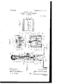
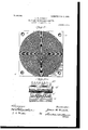
My invention will be more fully described hereinafter with reference to the accompanying drawings, in which the same is illustrated as embodied in a convenient and practical form, and in whichv Y Figure 1 is an elevational view, parts being shown in section; Fig. 2, a detail view on line 2 2, Fig. 3; Fig. 3, a plan view of a cuttingblade Fig. 4, a sectional View Online 4 4', Fig. l; Fig. 5, an elevational view looking from the right in Fig. 1 Fig. 6, .an end elevation of the rotary table Fig. 7, a sectional view on line 7 7, Fig. 6; Fig. 8, a sectional view on line 8 8, Fig. 6; Fig. 9, an enlarged plan view of the carrier and rollers carried thereby Fig. l0, a sectional view on line l() 10, Fig. 9;
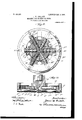
Flg. 11, a plan view of one of the corrugated plates, and Fig. l2 a detail sectional view through a portion of the plate and a coperating roller.
The same reference characters are used to designate the same parts in the several figures of the drawings.
Reference character A indicates a supporting base of any desired size upon which is mounted a vertical post B. A power-shaft C is journaled in a bearing a at the upper end of a standard A', projecting upwardly from the base A. The inner end of the shaft C is j ournaled in a bearing c on the post B.
C and C2 indicate belt pulleys, Aone of which is iixed to the shaft C, while the other of which is loose thereon.
Supported at the upper end of the post B is a horizontal bar B', upon which are mounted standards b and b2, upon which is journaled a shaft D. Fixed upon the shaft D are a series of graduated belt-pulleys d', d2, and d3, from any one of which a belt E extends to the corresponding pulley in a graduated series c', c2, and c3, fixed to the power-shaft C. A bevel-gear d is xed upon one end of the shaft D and meshes with a bevel-gear g, splined upon a vertical shaft G. The upper end of the shaft G immediately below the bevel-gear g is journaled in a bearing g/, formed at the outer end of the bar B. Surrounding the shaft G is a sleeve H, within which the shaft rotates. The sleeve is held Alongitudinally immovable relatively to the shaft by means of collars g2 and h2, fixed to the shaft immediately above and below the IIO center of the carrier.
sleeve, ball-bearings being preferably interposed between such collars and the adjacent ends of the sleeve. interposed between the collar g2 and the bar B' is a coil-spring G2, which surrounds the shaft G. The sleeve H is supported by n'ieans of brackets B2 and B2, extending from the post B and having circular bearings within which the sleeve is located and through which it reciprocates.
The sleeve H is provided with a series of teeth 7L', which slide within a vertical groove t3, formed in the bracket B3, such teeth and grooves serving to prevent the rotation of the sleeve. A mutilated gear 7c' cooperates with the teeth 7i.' and is xed upon a shaft K, the opposite ends of the latter being journaled in brackets b2 and 125, projecting from the bracket B3, as shown in Fig. 5. Fixed upon the shaft K is a bevel-gear f, the latter being fixed upon a stub-shaft F. The stubshaft F is journaled in any suitable form of bracket (indicated by dotted lines in Fig. 1) secured 'to the post B. The stub-shaft F is rovided with a series of graduated belt-pul eys F' F2 F3, any one of which may be connected, by means of a belt e, with one of a series of graduated pulleys f f 2, and f3 fixed upon the shaft D.
Fixed to the lower end of the shaft G is a disk p, having a circular flange P and a concentric collar P', located in axial alinement with the shaft G. The disk p serves as a carrier for supporting dies, such as the corrugated rollers, and cutting-disks. A plurality of radial rods R', R2, R2, R, R5, and R" are fixed at their outer ends to the lower edge of the circular Harige P and are supported at their inner ends by the collar P'. Rotatively supported upon the rods are dies in the form of corrugated rollers T' and T2, a plurality of such Irollers being located end to end, as shown in Fig. 10, so that those located nearer the center of the carrier may rotate at less speed than those located nearer the flange P. On one or more of the rods are rotatively supported cuttingdisks S', such disks being located predetermined distances from the In order that the rollers and cutting-disks may be freely rotated on their supportingaods, ball-bearings are provided, such as shown in Fig. l0, in which 7" indicates a collar clamped to the rod, between which and a loose collar r2 are located balls r. Secured to the outer ends of the rods and located within the circular [lange P is an annular plate P2, having cut-away portions 292, into which extend the roller-bearings on the respective shafts. Any suitable means may be provided for securing the annular plate P2 to the rod s-such, for instance, as clanip-scrcws p3. A small disk T, constituting an additional die and having concen tric corrugations, is fixed to the lower end of the collar' P in any suitable manner-such, for instance, as by having a pin t thereon extended within the collar P', to which it is se cured bya clampscrew t'.
A shaft L is fixedupon the base A below the shaft G in any suitable manner-such, for instance, as by having one end thereof supported in the post B and the other end thereof supported in a standard A2, projecting upwardly from the base. Rotatively surrounding the shaft L is a sleeve L', which is provided with radial arms Z2, at the outer ends of which are supported tables L2. The tables L2 are preferably four in number and are arranged to form a square. Secured to each table L2 is a plate O, having concentric corrugations. Any suitable means may be provided for securing the plates to the respective tables-such, for instance, as screws passing through holes 0, formed through the corners of the plates. A pair of radial holes is formed through the side of each plate O in alinement with the sleeve L. A bar N is located between each plate O and thensleeve L' and has its opposite ends extended laterally, as shown at a' a2. A pair of pins a is carried by each end a' a2 of each of the bars N, such pins passing through the pairs of holes extending through the tables L2 and plates O. A strap or yoke N2 serves as a guide for each pair of pins and is secured at each side of each table L2. Surrounding each pin of the pins a is a coil-spring N', bearing at one end upon the yoke a2 and its opposite end upon a' disk fixed to the pin a. A hook a3 projects inwardly from each of the bars N and engages a cam Z3, projecting radially from a collar L3, fixed to the shaft L.
The end of the sleeve L' adjacent the post B has fixed thereon a ratchet-wheel Z', with which cooperates a pawl m', carried by a plate M, the latter being rotatively mounted upon the shaft L intermediate of the post B and ratchet l. The lower end of a link m is pivotally connected to the plate M and at its opposite end is pivotally connected to an arm m2, rotatively carried by the shaft G. Any suitable means may be provided for securing the arm m2 to the shaft G-such, for instance, as a ring rotatively surrounding a reduced portion on the collar h2.
a2 indicates a rod secured to the standard A2 and projecting beneath the shaft L, which serves as a guide, around which passes the ICO sheet of copper V, the copper then passing around the plates O, as shown in Fig. 5.
In lieu of one of the rods R', &c., a bifurcated rod R, such as shown in Figs. 2 and 3, may be used. Upon the bifurcated portion r of the rod R is adjustably mounted a block s, through which extends a blade S. Any means may be provided for adjustably securing the blade within the block-such, for instance, as a clamp-screw U. A clamp-screw fa is also provided for securing the block s in any desired position upon the rod R.
The operation of my invention is as follows: A power-belt is applied to the pulley C or C2, fixed upon the power-shaft C, rotary motion from such power-shaft being transmitted to the shaft D by means of the belt E and graduated pulleys. Rotary motion is transmitted from the shaft D to the shaft G through the rneshed bevel-gears d and g. The carrier, consisting in the disk p and circular flange thereon, rotates with the shaft G and causes the corrugated rollers and cuttingdisks to rotate above the corrugated plate O immediately beneath the same. The end of a sheet of copper V, which has been previously interposed between 4the plate and carrier, is consequently corrugated and cut into annular gaskets. The size of the gaskets may be determined by adjusting the cuttingdisks upon their supporting-rods. The central portion of the copper beneath the corrugated disk T is formed into a corrugated disk, While the portion of the copper between such disk and the outer ends of the rollers is formed into concentric annular gaskets. After the carrier at the lower end of the shaft G has been rotated a predetermined distance the sleeve H is elevated through the engagement of the teeth on the interrupted gear 7c with the teeth 71, on the sleeve. The elevation of the sleeve carries with it the shaft G and also the carrier at the lower end thereof. The corrugated rollers and cutting-disks are consequently elevated above the table and the latter rotated to bring another section of sheet-copper in position beneath the carrier, so that when the teeth on the mutilated gear k have passed out of engagement with the teeth on the sleeve the latter is forced downwardly by the spring G2 and the rollers and cutting-disks forced into engagement with the new section of copper. Rotation of the tables L2 is effected by means of the oscillation of the plate M by means o1 the link m and arm m2, such oscillation of the plate being communicated through the pawl m and ratchet l to the sleeve L, which carries the tables. The -downward movement of the sleeve II oscillates the plate M, so that the pawl m engages a succeeding tooth on the ratchet Z preparatory to again rotating the tables a distance of ninety degrees, when the sleeve is again elevated. In orderthat the sheet of copper may be retained around the plates on the tables, the pairs of pins n are provided. The tension of the springs N surrounding the pins is such that the ends of the pins are forced through the copper, and the atter thereby carried with the plates as they are rotated. The guide-rod a2 causes the copper to lie closely against the plates. After each plate O has served in conjunction with the corrugated rollers and cutting-disksA to convert the copper plate between the same into gaskets and the table is given a quarterturn the hook n3 on the bar N beneath the corresponding plate O engages the cam Z3, l
and thereby withdraws the pins n from engagement with the scrap left after the making of the gaskets. As each hook n3 passes out of contact with the cam Z3 the springs project the pins beyond the plates, so that they will engage the copper as'it is drawn around the successive plates. It is obvious that the cutting-disks S engage the grooves of the corrugations in the plates, and in order that the copper may be cut above the ribs of the corrugations a cutting-knife, such as shown in Figs. 2 and 3, must be employed. By the use of such knife it is therefore possible to' cut from the copper sheet annular gaskets eX- tending between a groove in the plate O and the top of one of the concentric ribs. It is obvious that the shaft G continues to rotate even when elevated owing to the spline between the same and the bevel-gear G. It is also obvious that the speed of rotation of the carrier may be varied by adjusting the belt E upon the coperating graduated pulleys and that the interval between the reciprocations of the carrier may be varied by adjusting the belt e upon the coperating graduated pulleys.
By my machine a roll of copper sheet is automatically cut into annular corrugated gaskets, each operation serving to form a plurality of concentric gaskets, and after each operation the rotation of the tables removes the gaskets from beneath the carrier and allows the same to fall at one side of the machine. IVhile I have s'hown dies consisting in the corrugated disk T and the corrugated rollers, yet it is evident that such disk may be used by itself to convert into gaskets by friction a narrow strip of copper and that the corrugated rollers may also be used without the em loyment of the corrugated disk.
While it is preferable to employ automatic means, such as the rotating series of tables, to feed the strip of copper between the corrugated plates and relatively rotating dies, yet it is obvious that other means may be employed for interposing the copper between the dies and coperating corrugating-plate.
My improved carrier with the corrugated rollers and cutting-disks is capable of being attached to other forms af drill-presses than that shown herein, and I consider such use of my improved carrier as coming within the scope of my invention.
Having now fully described my invention, what I claim as new, and desire to secure by Letters Patent, is
1. In a machine for making corrugated gaskets, the combination with a plate having concentric corrugations, of a die having'corrugations corresponding to those of said plate, means for relatively rotating said die and said plate, and automatic means for intermittently reciprocating said die toward and away from said plate.
2. In a machine for making corrugated IOO gaskets, the combination with a plate having concentric corrugations, of a die having corrugations to correspond to those of said plate a carrier for supporting said die, means for rotating said carrier relative to said plate, and automatic means lor intermittently moving said carrier and plate toward and away from each other.
3. In a machine for making corrugated gaskets, the combination with a plate having concentric corrugations, ol a die having corrugations corresponding to those of said plate, a carrier f or supporting said die, a cutter mounted upon said carrier, means for rotating said carrier relatively to said plate, and means for intermittently reciprocating` said carrier toward and away from said plate.
4. In a machine for making corrugated gaskets, the combination with a plate having concentric corrugations, of a roller having corrugations corresponding to those of said plate, a carrier upon which said roller is ournaled, means for rotating said carrier relatively to said plate, and automatic means for intermittently reciprocating said carrier toward and away from said plate.
5. ln a machine for making corrugated gaskets, the combination with a plate having concentric corrugations, of' a roller having corrugations corresponding to those oi said plate, a carrier upon which said roller is ournaled, a cutting-disk journaled upon said carrier, means for rotating said. carrier relatively to said plate, and means for intermittently reciprocating said carrier toward and away from said plate.
6. ln a machine of the character described, the combination with a plate having concentric corrugations, a carrier located adjacent said plate, radial rods upon said carrier, rollers journaled upon said rods having corrugations corresponding with those of said plate, cutting-disks journaled upon said rods,
means for rotating said carrier relatively to said plate, and means 'lor intermittently moving said carrier andy plate toward and away from each other.
7. In a machine of the character described, the combination with a plate having concentric corrugations, a carrier located ad jacent said plate, radial rods upon said carrier, rollers `journaled upon said rods having corrugations corresponding with those of said plate, cutting-disks journaled upon said rods, a corrugated disk Alixed eoncentrically to said carrier and located between the inner ends of said rollers, means l'or rotating said carrier relatively to said plate, and means for intermittently moving said carrier and plate toward and away vfrom each other.
8. In a machine of the character described, the combination with a plate having concentric corrugations, a die having corrugations corresponding to those of said plate, a carrier for said die, a shaft to which said carrier is fixed, means for rotating said shaft, a sleeve loosely surrounding but longitudinally immovable relatively to said shaft, and means engaging said sleeve for intermittently reciprocating said carrier.
9. In a machine of the character described, the combination with a plurality of plates each having concentric corrugations, of a die having corrugations corresponding to those of said plates, means for rotating said die relatively to said plate, means for successively locatingv each of said plates beneath said die, and means for intermittently reciprocating said die toward and away from the adjacent plate.
10. In a machine of the character described, the combination with a plurality of plates each having concentric corrugations, a rotary table upon which said plates are supported, a die having corrugations corresponding to those of said plates, means for rotating said table to successively locate said plates beneath said die, and means for intermittently reciprocating said die toward and away from the adjacent plate.
11. In a machine of the character described, the combination with a rotary table, of a plurality of plates each having concentric corrugations, a die having corrugations corresponding with those of said plates, a carrier supporting said die7 means for rotating said carrier, and means for intermittently reciprocating said carrier away from said table and coincidently rotating said table to locate a following plate beneath said carrier.
l2. In a machine of the character de scribed, the combination with a square table journaled to rotate in a vertical plane, a plate having concentric corrugations secured to each 'face of said table, a die having corrugations corresponding to those of said plates, means for rotating said die relatively to the cooperating plate, means for intermittently reciprocating said die away 'from said table and coincidently rotating said table to locate a 'following plate beneath said die.
13. ln a machine for making corrugated gaskets, the combination with a plate having concentric corrugations, of a die having corrugations corresponding to those of said plate, means `for rotating said die relatively to said plate, means for intermittently reciprocating said die toward and away from said plate, and means for automatically interposing sheet-copper between said die and plate.
14. In a machine of the character described, the combination with a square table journaled to rotate in a vertical plane, a plate having concentric corrugations secured to each lace of said table, a die having corru-A gations corresponding to those of said plates, means for intermittently reciprocating said die away `from said table and coincidently rotating said table to locate another plate be- IOO neath said die, and means for automatically securing a sheet of copper to said table.
15. In a machine of the character de scribed, the combination with a square table journaled to rotate in a vertical plane, a plate having concentric corrugations secured to each face of said table, a die having corrugations corresponding to those of said plates, radially-reciprocating pins carried by said tables, means for projecting said pins through said plates to engage copper sheet and secure the same to said table, and means for disengaging said pins from the copper plate.
16. In a machine for making corrugated gaskets, the combination with a plate having corrugations, of a die having corrugations corresponding to those of said plate, a carrier for supporting said die, a plurality of cutters mounted upon said carrier at different distances from its aXis, and means for relatively rotating said carrier and plate.
17. In a machine for making corrugated gaskets, the combination with a plate having concentric corrugations, of a die having corrugations corresponding to those of said plate, a carrier for supporting said die, a cutter mounted upon said carrier, means for radially adjusting the position of said cutter uponsaid carrier, and means for relatively rotating said carrier and said plate.
18. In a machine for making corrugated gaskets, the combination with a plate having concentric corrugations, of a plurality of rollers having corrugations corresponding to those of said plate, a carrier upon which said rollers are j ournaled, a plurality of cuttingdisks journaled upon said carrier and located different distances from its axis, means for relatively rotating said carrier and said plate, and means for relatively moving said carrier and plate toward and away from each other.
19. In a machine of the character described, the combination with a plate having concentric corrugations, a carrier located adjacent said plate, radial rods upon said carrier, rollers ournaled upon said rods having corrugations corresponding with those of said plate, means for relatively rotating said carrier and said plate, and means for relatively moving said carrier and plate toward and away from each other.
20. In a machine of the character described, the combination with a plate having concentric corrugations, a carrier located adjacent said plate, radial rods upon said carrier, rollers j ournaled upon said rods having corrugations corresponding with those of said plate, cutting-disks journaled upon said rods at different distances from the axis of said carrier, means for adjusting said cuttingdisks radially with respect to said carrier, means for relatively rotating said carrier and plate, and means for relatively moving said carier and plate toward and away from each ot er.
In testimony whereof I sign this speciiication in the presence of two witnesses.
JAMES W. GUILLOTT.
Witnesses:
GEO. L. WILKINSON, C. A. MULLEN.
Priority Applications (1)
| Application Number | Priority Date | Filing Date | Title |
|---|---|---|---|
| US24442605A US809256A (en) | 1905-02-06 | 1905-02-06 | Machine for making gaskets. |
Applications Claiming Priority (1)
| Application Number | Priority Date | Filing Date | Title |
|---|---|---|---|
| US24442605A US809256A (en) | 1905-02-06 | 1905-02-06 | Machine for making gaskets. |
Publications (1)
| Publication Number | Publication Date |
|---|---|
| US809256A true US809256A (en) | 1906-01-02 |
Family
ID=2877737
Family Applications (1)
| Application Number | Title | Priority Date | Filing Date |
|---|---|---|---|
| US24442605A Expired - Lifetime US809256A (en) | 1905-02-06 | 1905-02-06 | Machine for making gaskets. |
Country Status (1)
| Country | Link |
|---|---|
| US (1) | US809256A (en) |
-
1905
- 1905-02-06 US US24442605A patent/US809256A/en not_active Expired - Lifetime
Similar Documents
| Publication | Publication Date | Title |
|---|---|---|
| US809256A (en) | Machine for making gaskets. | |
| US154450A (en) | Improvement in machines for perforating paper | |
| US715774A (en) | Wire chasing or marking machine. | |
| US700141A (en) | Button-fly-scalloping machine. | |
| US976877A (en) | Punching-machine. | |
| US1016547A (en) | Machine for stamping and forming sheet-metal articles. | |
| US1115347A (en) | Sheet-metal-cutting machine. | |
| US610329A (en) | meisel | |
| US1282077A (en) | Feeding-table for button-blanks. | |
| US716051A (en) | Wire cutting and straightening machine. | |
| US987626A (en) | Stencil-machine. | |
| US659192A (en) | Button-drilling machine. | |
| US1088308A (en) | Machine for ornamenting window-cames and the like. | |
| US475315A (en) | Die and machine for rolling cutlery | |
| US900257A (en) | Perforating-machine. | |
| US138264A (en) | Improvement in machines for cutting out planchets of sheet metal | |
| US548784A (en) | Machine for cutting knit fabrics | |
| US283016A (en) | Automatic numbering-machine | |
| US498411A (en) | strauss gr | |
| US1005298A (en) | Machine for cutting solder rings and applying the same to the edges of can-caps. | |
| US685531A (en) | Machine for making sheet-metal oval or circular frames. | |
| US643640A (en) | Machine for making expanded metallic lathing. | |
| US590275A (en) | Machine for forming bushing-ferrules | |
| US237303A (en) | Heeman milleb | |
| US477086A (en) | Charles ii |