US809237A - Semaphore mechanism. - Google Patents
Semaphore mechanism. Download PDFInfo
- Publication number
- US809237A US809237A US24931605A US1905249316A US809237A US 809237 A US809237 A US 809237A US 24931605 A US24931605 A US 24931605A US 1905249316 A US1905249316 A US 1905249316A US 809237 A US809237 A US 809237A
- Authority
- US
- United States
- Prior art keywords
- housing
- armature
- pole
- arm
- secured
- Prior art date
- Legal status (The legal status is an assumption and is not a legal conclusion. Google has not performed a legal analysis and makes no representation as to the accuracy of the status listed.)
- Expired - Lifetime
Links
- 230000007246 mechanism Effects 0.000 title description 13
- 230000000153 supplemental effect Effects 0.000 description 22
- 230000033001 locomotion Effects 0.000 description 14
- 239000011521 glass Substances 0.000 description 10
- 239000002184 metal Substances 0.000 description 8
- 229910052751 metal Inorganic materials 0.000 description 8
- 239000011810 insulating material Substances 0.000 description 4
- 239000000696 magnetic material Substances 0.000 description 4
- 229910000831 Steel Inorganic materials 0.000 description 3
- 239000010959 steel Substances 0.000 description 3
- 229920001875 Ebonite Polymers 0.000 description 2
- 238000010276 construction Methods 0.000 description 2
- 238000003780 insertion Methods 0.000 description 2
- 230000037431 insertion Effects 0.000 description 2
- 239000000463 material Substances 0.000 description 2
- 229910001018 Cast iron Inorganic materials 0.000 description 1
- RYGMFSIKBFXOCR-UHFFFAOYSA-N Copper Chemical compound [Cu] RYGMFSIKBFXOCR-UHFFFAOYSA-N 0.000 description 1
- 241000219171 Malpighiales Species 0.000 description 1
- 230000000694 effects Effects 0.000 description 1
- 239000004744 fabric Substances 0.000 description 1
- XEEYBQQBJWHFJM-UHFFFAOYSA-N iron Substances [Fe] XEEYBQQBJWHFJM-UHFFFAOYSA-N 0.000 description 1
- 229910052742 iron Inorganic materials 0.000 description 1
- QSHDDOUJBYECFT-UHFFFAOYSA-N mercury Chemical compound [Hg] QSHDDOUJBYECFT-UHFFFAOYSA-N 0.000 description 1
- 229910052753 mercury Inorganic materials 0.000 description 1
- 239000000203 mixture Substances 0.000 description 1
- 238000012856 packing Methods 0.000 description 1
- 230000011664 signaling Effects 0.000 description 1
- 239000010454 slate Substances 0.000 description 1
Images
Classifications
-
- B—PERFORMING OPERATIONS; TRANSPORTING
- B61—RAILWAYS
- B61L—GUIDING RAILWAY TRAFFIC; ENSURING THE SAFETY OF RAILWAY TRAFFIC
- B61L5/00—Local operating mechanisms for points or track-mounted scotch-blocks; Visible or audible signals; Local operating mechanisms for visible or audible signals
- B61L5/06—Electric devices for operating points or scotch-blocks, e.g. using electromotive driving means
- B61L5/065—Construction of driving mechanism
Definitions
- My present invention relates to certain new and useful improvements in semaphore mechanisms, and the same is more particularly adapted. for use in connection with my improved system of electric signaling and switch-setting for railroads disclosed in m copending application, filed October 28, 1904, Serial No. 280,521.
- my invention seeks to provide a semaphore mechanism always under the control of the operatorand which includes means for closing branch circuits to operate indicating devices at the operators station and to cut in a signal-lamp in the semaphorecasing to give a light-signal.
- my invention comprises a casing adapted to be hermetically closed and forming the field-magnet of an electric motor, the pole-pieces of which inotor are integrally formed with the casing.
- An armature is rotatably mounted between the pole-pieces in the casing and has its shaft extended to without the casing to receive the semaphore-blade, and means are connected with the armature for holding the same in its adjusted positions when the energizing-current has ceased.
- the invention also includes circuit-closers within the casing adapted to be operated by the motor armature and a supplemental chamber below the main chamber of the casing in which an electric lamp and resistancecoil are mounted, which chamber is provided with windows adapted to cooperate with the colored glass of the tail-plates of the semaphore for giving light-signals, said casing being provided with apertures for Ventilating said supplemental chamber.
- the invention also has for its object to so construct the casing that it will serve as a junction-box for the various terminals.
- 8 designates a cast-iron or soft-steel housing having two oppositely-arranged magnet-cores Sa and 8b that are cast with the frame in one piece.
- I make the upper pole-piece 8a smaller in width than the lower one and provide it with a poleshoe 8C, which covers the same arc as the lower piece 8b.
- housing 8 on its side walls and oppositely disposed to each other are two flat surfaces 8@ Se, respectively, while the front and rear walls of the housing are each provided with a large rectangular opening to allow of ready access to the interior of the housing and to permit insertion of the interior parts through said opening.
- Both field-coils consist of insulated copper wire and are connected in series to each other and wrapped in insulating material, such as cloth or tape.
- the upper coil 53a rests on metallic angle-pieces 54a 54h, which are respectively fastened to the rear and front sides of the pole-piece 8EL by screws, as clearly shown in Figs. 1 and 2.
- armature 55aof the Siemens shuttle type Arranged concentrically between the polepieces 8a 8b is an armature 55aof the Siemens shuttle type, as shown in detail in Fig. 3. On the soft-iron core 55a the energizing armature-coil 55b is wound, proper insulatin material being interposed between thev coi and the armature in the usual manner,-
- Fig. 4 is a side view IOO IOS
- C 55d designat'e disks of non-magnetic metal, which are secured to the armature 55a at each end by suitable screws, as shown.
- the disks 55C and 55d are provided with central hubs, which are drilled, reamed, and pressed tothe ends 56a and 56h, respectively, of two short steel shafts, to which they may be further secured by steel pins, as shown in Fig. 1.
- the armature-disk 55d is provided with a pair of insulating-bushings 55e and 55f, respectively, of hard liber, hard rubber, or other suitable material to permit passage of the ends 55k and 55, respectively, of the armature-coil 55", as clearly shown in Fig. 1 of the drawings.
- the ends 55k and 55l are helically rolled up to serve as flexible connections and are joined at their ends with the metallic stationary terminal blocks 57 a 57 b.
- the terminal plates are fastened oppositely to each other on the flat surfaces 8d and 8e of the housing-wall, as shown in Fig. 1.
- 55i designates a metallic lever secured by screws 55g and 55h to the armature-disk 55d, but insulated therefrom by a plate of hard iiber or hard rubber and by screw-bushings of similar insulating material in the usual manner.
- the screw 55g is longer than the screw 55h, runs with suitable clearance through the disk 55d, and is fastened in the armaturebody 55a. (See dotted lines in Fig. 2.)
- the aforesaid rectangular openings in the front and rear walls of the housing are covered by weather-proof cap-plates 58a and 58h, respectively, which plates are secured to the housing by a number of cap-screws, and the said plates 58L and 58b are formed with bearings or journals 58C and 58d, respectively, for the short shaft-section 56C and 56d of the armature.
- the upper portions of the plates 58a and 58b are provided with rectangular apertures, which are closed by metallic covers 58e and 58f, respectively, a soft-rubber packing and a plurality of thumb-screws 58g beingprovided for each plate to secure a weather-proof joint between the plates and they cover. These apertures serve as handholes to permit the insertion of the operators hand to adjust or inspect the mechanism within the housing.
- the housing 8 is covered with a roof 59, of galvanized sheet-iron, as shown in Figs. 1 and 2.
- the shaft 56C projects outside of the housing through the bearings 58c and terminates in the stud 56", to which the metalic hub 60 is secured by a pin, as shown.
- the hub 60 is provided with a flange 60a, to which the signal-arm 3 of the semaphore-blade is secured.
- the tail portion 3a of the semaphore-blade which carries the usual colored disk 3b for effecting nightsignals, may be either of a curved shape, as shown in dotted lines in Fig. 1, or it may be of any other design which may be found to be desirable to use. In order to balance the weight of the signal-arm and tail-plate, the latter may be made of a heavier piece of sheet metal than the former.
- the total swinging motion of the semaphore-blade occupies an angle of about sixty degrees, and in order to mechanically lock said blade to its final positions a toggle-spring device (shown in detail in Figs. 4 and 5) is provided.
- the toggle-spring device comprises an eyebolt 62, whose eye 62a is pivotally mounted on a stud 61, (see Fig. 2,) secured into an aperture in the pole 8a, and the said eyebolt is carried by a bracket member 63 and passes through bearings 63'LL and 63b in the said bracket member, a collar 62h, (see Fig.
- the bracket 63 is provided with a boss 63d, into which a pivotscrew 63C is screwed.
- 65 designates a metallic sleeve secured to the shaft-section 56a, which sleeve is provided with a lever or arm 65g', which is fulcrumed on the pole 63C, before mentioned.
- a metallic bent lever 70 having a setscrew 70a.
- the coil-spring 84 connects lever 70 with a stud 84a, fastened to the extending portion 69a of the metallic plate 69 and causes the set-screw to rest on said extending portion in the manner shown in the righthanded circuit-closer of Fig. 1.
- each bent lever 70 terminates in a cross-arm 70, (see Fig. 6,) which carries a pivot-pointed metallic set'- screw 70d.
- Each of the set-screws 7 0d are secured' to their respective positions toward their respective arms by means of counternuts and are directly arranged over their respective mercury-cups 67 C and 67 d.
- a supplemental casing 9 (see Figs. 1 and 2) with openings 9a and 9b inits front and rear sides, which openings are disposed oppositely to each other.
- the casing 9 carries at its bottom a tubular portion 9, as shown.
- the apertures 9EL and 9b I fasten tubular metallic caps 9d and 9e, that are covered at their outer ends by transmitting-disks 9h and 9i, of which the disk 9e is usually composed of colored glass. These glass disks are held in place by metallic rings 9f and 9g, secured to the caps 9a and 9e by screws, as shown.
- a signal-lamp 16 Arranged centrally within the casing 9 is a signal-lamp 16, the socket for which is fastened into the upper wall of the casing 9.
- Said lamp 16 may be of the ordinary incandescent type and supplied with current in any approved manner-such, for instance, as disclosed in my copending application before referred to.
- a resistance 18 is placed within the casing 9, which resistance may be substituted for the lamp 16 when my present invention is used with the system disclosed in my copending application before referred to, or the said resistance 18 may be placed outside of the casing, if desired.
- the resistance 18 consists of a coil of insulated wire wound upon .a spool-frame of insulating material, and the wire of the resistance 19 should preferably be such a composition of vmetals that will not change its resistance to any considerable degree under variations of temperature.
- the casing is lfurther provided with apertures 9a to allow of air circulation to keep the chamber within the casing 9 at as low a temperature as possible.
- armature for operating the circuit-@losers at times, a semaphore-blade on the outside of the housing coperatively connected to turn with the armature, said blade having a tailpiece provided with a colored glass, a supplemental housing formed with and below ,the first-mentioned housing, said supple- 4mental housing adapted to receive an incandescent lamp and a resistance-coil, said supplemental housing having apertures diagonally opposite each other, one of which is adapted to register with the tailpiece-glass when the semaphore is in one position, and terminal blocks for making wire connections mounted within the housing.
- a mechanism of the character stated a housing of magnetic material, pole-pieces integrally formed within said housing energizing-coils carried by said pole-pieces, an armature mounted for limited rotatable movement between the pole-pieces, circuitclosers within the housing, means carried by the armature for operating the circuit-closers at times, a semaphore-blade on the outside of the housing coperatively connected to turn with the armature, said blade having a tailpiece provided with a colored glass, a supplemental housing formed with and below the first-mentioned housing, said supplemental housing adapted to receive an incandescent lamp and a resistance-coil, said supplemental housing having apertures diagonally opposite each other, one of which is adapted to register with the tailpiece-glass when the semaphore is in one position, terminal blocks for making wire connections mounted within the housing, and a supplemental roof for the housing.
- a housing formed of magnetic material, pole-pieces integrally formed within said housing, one of said pole-pieces being longer than the other, energizing-coils carried by said pole-pieces, an armature mounted for limited rotary movement between said pole-pieces, said housing having openings at its ends, closurecaps for said openings, said closure-caps being provided with bearings, said armature having shaft portions extending through said closure-cap bearings, a semaphore-blade secured to one of said shaft portions, circuitclosers within the housing, means carried by the armature for operating the circuit-closers, and toggle-spring devices for holding the armature to its moved positions.
- a housing formed of magnetic material, pole-pieces integrally formed within said housing, one of said pole-pieces being longer than the other, energizing-coils carried by said pole-pieces, an armature mounted for limited rotary movement between said pole-pieces, said housing having openings at its ends, closure-caps for said openings ,said closure-caps being provided with bearings, said armaturehaving shaft portions extending through said closure-cap bearings, a semaphore-blade secured to one of said shaft portions, circuit-closers within the housing, means carried by the armature for operating the circuit-closers, toggle-spring devices for holding the armature to its moved positions, said housing having a supplemental chamber at its under side and being provided with a collar portion by means of which it may be secured to a pole, an incandescent lamp and a resistance-coil in said supplemental chamber, said supplemental chamber having ventilating-apertures, said supplemental chamber having a pair
- va housing of magnetic metal a pair of polepieces integrally formed therewith within the housing, one of said pole-pieces being of greater length than the other, an energizingcoil mounted on said longer pole-piece, means for holding said coil in place on said longer pole-piece, an energizing-coil for the other pole-piece, said housing having openings in its end walls, closure-plates having bearings and integrally-formed drip-pans, an armature, a disk secured to each end of the armature, short shafts secured to each disk 'and passing through the bearings in the closureplates, an arm carried by one of said shafts, a bracket pivotally connected to said arm, an eyebolt carried by said bracket, said eyebolt being pivotally secured to the longer polepiece, a collar and a coil-spring on said eyebolt for forcing the eyebolt in one direction, one of said armature-shafts proj ecting through its closure plate, and a semaphore blade mounted on said last-named shaft-
- a housing of magnetic metal a pair of polepieces integrally formed therewith within the housing, one of said pole-pieces being of greater length than the other, an energizingcoil mounted on said longer pole piece, means for holding said coil in place on said longer pole piece, an energizingcoil for the other pole-piece, said housing having openings in its end walls, closure-plates for said openings, said closure-plates having bearings and integrally-formed drip-pans, an armature, a disk secured to each end of the armature, short shafts, secured to each disk and passing through the bearings in the closureplates, an arm carried by one of said shafts, a bracket pivotally connected to said arm, an eyebolt carried by said bracket, said eyebolt being pivotally secured to the longer pole-piece, a collar and a coil-spring on said eyebolt for forcing the eyebolt in one direc- IOO IIO
- one of said armature-shafts projecting through its closure-plate a vsemaphoreblade mounted on said last-namedshaft-sections, means mounted within the casing and adapted to be engaged by said shaft-arm as the armature has reached the' limit of its movement in each direction to serve as a buffer-spring therefor, circuit-closers mounted within the casing, an arm secured to one of said armature-disks for operating the circuit-closers.
- a housing of magnetic metal a pair of polepieces integrally formed therewith within the housing, one of said pole-pieces beingof greater length than the other, an energizingcoil mounted on said longer pole-piece, means for holding said coil in place on said longer pole-piece, an energizing-coil Vfor the other pole-piece, said housing having openings in its end walls, closure-plates for said openings, said closure-plates having bearings and integrally-formed drip -pans, an armature, a disk secured to each end of the armature, short shafts secured to each disk and passing through the bearings in each closure-plate, an arm carried by one of said shafts, a bracket pivotally connected to said arm, an eyebolt carried by said bracket, said eyebolt being pivotally secured to the longer pole-piece, a collar and a coil-spring on said eyebolt for forcing the eyebolt in one direction, one of said armature-shafts projecting through its closure plate,
- a housing of magnetic metal a pair of polepieces integrally formed therewith within the housing, one of said pole-pieces being of greater length than the other, an energizingcoil mounted on said longer pole-piece, means for holding said coil in place on said longer pole piece, an energizing coil for the other pole-piece, said housing having openings in its end walls, closure-plates for said openings, said closure-plates having bearings and integrally-formed drip-pans, an armature, a disk secured to each end of the armature, short shafts secured to each disk and passing through the bearings in the closure-plates, an arm carried by one of said shafts, a bracket pivotally connected to said arm, an eyebolt carried by said bracket, said eyebolt being plvotally secured to the longer pole-piece, a collar and a coil-spring on said eyebolt for forcing the eyebolt in one direction, one o1 said armature-shafts projecting through its clossure
- a housing of magnetic metal a pair of' polepieces integrally formed therewith within the housing, one of said pole-pieces being 'of greater -length than the other, an energizingcoil mounted on said longer pole -piece, means for holding said coil in place on said longer'pole-piece, an energizing-coil for the other-pole-piece, said housing having openings in its end walls, closure-plates having bearings and integrally-formed drip-pans, an armature, a disk secured to each end of the armature, short shafts secured to each disk and passing through the bearings in the closure-plates, an arm carried by one of said shafts, a bracket pivotally connected to said arm, an eyebolt carried by said bracket, said eyebolt being pivotally connected to the longer pole-piece, a collar'and a coil-spring on said longer pole for forcing the eyebolt in one direction, one of said armature-shafts projecting through its closure-plate, a se
- said supplemental chamber having apertures in its end walls, tubular members held in said apertures, transparent closure members for the outer ends of said tubular members, said semaphore-blade having a tailpiece, a colored transparent disk vcarried by said tailpiece for registering with said transparent closer members of one of said tubular members.
- a housing of magnetic metal a pair of polepieces integrally formed therewith within the housing, one of said pole-pieces being of greater length than the other, an energizingcoil mounted on said longer pole-piece, means for holding said coil in place on said longer pole-piece, an energizing-coil for the other pole-piece, said housing having openings in its end walls, closure-plates for said openings, said closure-plates having bearings yand integrally-formed drip-pans, an armature, a disk secured to each end of the armature, short shafts secured to each disk and passing through the bearings in the closureplates, an arm carried by one of said shafts,
- a bracket pivotally connected to said arm, an eyebolt carried by said bracket, said eyebolt being pivotally secured to the longer pole-piece, a collar and a coil-spring on said eyebolt, 'for forcing the eyebolt in one direction, ⁇ one of said armature-shafts projecting Y, gthrough its closure-plate, a semaphore-blade ymounted on said last-named shaft-section,
- each of said hbusing closer-plates having an aperture, a closure member for said apertures, means for detachably securing said lastnamed closure-plate members over the closure-plate apertures hermetically substantially as shown and described.
- a housing pole-pieces within the housing, energizing-coils carried by said pole-pieces, an armature mounted for rotary movement between the pole-pieces, circuit-closers within the housing, means Within the housing for operating said circuit-closers, a semaphoreblade without the housing cooperatively connected to turn with the armature, substan ⁇ tially as shown and described.
- a housing pole-pieces within the housing, energiZing-coils carried by said pole-pieces, n armature mounted Jfor rotary movement between the pole-pieces, circuit-closers mounted within the housing, means within the housing for operating said circuit-closers, a semapliore-blade without the housing coperatively connected to turn with the armature,
- said blade having a tailpiece provided with an indicating-glass, a supplemental housing below the irst supplemental housing, a signal-lamp within said supplemental housing, said supplemental housing having apertures adapted to register with the tailpiece-glass when the semaphore is in one position.
Landscapes
- Engineering & Computer Science (AREA)
- Mechanical Engineering (AREA)
- Reciprocating, Oscillating Or Vibrating Motors (AREA)
Description
UNITED STATES PAgrnNT OFFIOE.
Specification of Letters Patent.
Patented Jan. 2, l1906.
Application filed March 9,1905. Serial N0. 249,316-
To all whom it may concern:
Be it known that I, BRUNO OTTO WAGNER, at present residing at Swissvale, in the county of Allegheny and State of Pennsylvania, have invented certain new and useful Improvements in Semaphore Mechanisms, of which the following is a specification.
My present invention relates to certain new and useful improvements in semaphore mechanisms, and the same is more particularly adapted. for use in connection with my improved system of electric signaling and switch-setting for railroads disclosed in m copending application, filed October 28, 1904, Serial No. 280,521.
Primarily my invention seeks to provide a semaphore mechanism always under the control of the operatorand which includes means for closing branch circuits to operate indicating devices at the operators station and to cut in a signal-lamp in the semaphorecasing to give a light-signal.
In its generic nature my invention comprises a casing adapted to be hermetically closed and forming the field-magnet of an electric motor, the pole-pieces of which inotor are integrally formed with the casing. An armature is rotatably mounted between the pole-pieces in the casing and has its shaft extended to without the casing to receive the semaphore-blade, and means are connected with the armature for holding the same in its adjusted positions when the energizing-current has ceased.
The invention also includes circuit-closers within the casing adapted to be operated by the motor armature and a supplemental chamber below the main chamber of the casing in which an electric lamp and resistancecoil are mounted, which chamber is provided with windows adapted to cooperate with the colored glass of the tail-plates of the semaphore for giving light-signals, said casing being provided with apertures for Ventilating said supplemental chamber.
The invention also has for its object to so construct the casing that it will serve as a junction-box for the various terminals.
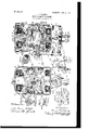
With other objects than have heretofore been enumerated the invention comprises certain details of construction and novel arrangement of parts, all of which will be first described in detail and then speciiically pointed out in the appended claims, refer-Y ence being had to the accompanying drawings, in which- Figure l is a vertical longitudinal section on the line Q R S T U V of Fig. 2 looking in the direction of the arrow. Fig. 2'is a central vertical section through the semaphorehousing. Fig. 3 is a perspective view of the semaphore-armature. of the toggle-spring device. Fig. 5 is a vertical longitudinal section on the line 5 5 of Fig. 4. Fig. 6 is a side view of the circuitclosing device. Fig. 7 is a top view of the circuit-closing device. Fig. 8 is a front view of the swing-motion adjusting devices for the semaphore-blade.
Referring now to the accompanying drawings, in which like numerals of reference indicate like parts in all the figures, and, referring particularly to Figs. l and l2, it will be seen that 8 designates a cast-iron or soft-steel housing having two oppositely-arranged magnet-cores Sa and 8b that are cast with the frame in one piece. To provide ample space for the free operation of the two circuit-closing devices (hereinafter again referred to) within the upper portion of the housing, I make the upper pole-piece 8a smaller in width than the lower one and provide it witha poleshoe 8C, which covers the same arc as the lower piece 8b.
Within the housing 8 on its side walls and oppositely disposed to each other are two flat surfaces 8@ Se, respectively, while the front and rear walls of the housing are each provided with a large rectangular opening to allow of ready access to the interior of the housing and to permit insertion of the interior parts through said opening.
53a and 531 designate the energizing fieldcoils for the ole-pieces 8at 8b, respectively, the upper fid-coil being larger than the lower one to compensate for the increased magnetic leakage of the .said pole. Both field-coils consist of insulated copper wire and are connected in series to each other and wrapped in insulating material, such as cloth or tape. The upper coil 53a rests on metallic angle-pieces 54a 54h, which are respectively fastened to the rear and front sides of the pole-piece 8EL by screws, as clearly shown in Figs. 1 and 2.
Arranged concentrically between the polepieces 8a 8b is an armature 55aof the Siemens shuttle type, as shown in detail in Fig. 3. On the soft-iron core 55a the energizing armature-coil 55b is wound, proper insulatin material being interposed between thev coi and the armature in the usual manner,-
Fig. 4 is a side view IOO IOS
IIO
C 55d designat'e disks of non-magnetic metal, which are secured to the armature 55a at each end by suitable screws, as shown. The disks 55C and 55d are provided with central hubs, which are drilled, reamed, and pressed tothe ends 56a and 56h, respectively, of two short steel shafts, to which they may be further secured by steel pins, as shown in Fig. 1.
The armature-disk 55d is provided with a pair of insulating-bushings 55e and 55f, respectively, of hard liber, hard rubber, or other suitable material to permit passage of the ends 55k and 55, respectively, of the armature-coil 55", as clearly shown in Fig. 1 of the drawings. The ends 55k and 55l are helically rolled up to serve as flexible connections and are joined at their ends with the metallic stationary terminal blocks 57 a 57 b. In practice there are three terminal blocks in parallel, but insulated from each other on a plate of slate, lava, or other insulating material 57g and 57h, respectively. The terminal plates are fastened oppositely to each other on the flat surfaces 8d and 8e of the housing-wall, as shown in Fig. 1.
55i designates a metallic lever secured by screws 55g and 55h to the armature-disk 55d, but insulated therefrom by a plate of hard iiber or hard rubber and by screw-bushings of similar insulating material in the usual manner. The screw 55g is longer than the screw 55h, runs with suitable clearance through the disk 55d, and is fastened in the armaturebody 55a. (See dotted lines in Fig. 2.)
The aforesaid rectangular openings in the front and rear walls of the housing are covered by weather-proof cap-plates 58a and 58h, respectively, which plates are secured to the housing by a number of cap-screws, and the said plates 58L and 58b are formed with bearings or journals 58C and 58d, respectively, for the short shaft-section 56C and 56d of the armature. The upper portions of the plates 58a and 58b are provided with rectangular apertures, which are closed by metallic covers 58e and 58f, respectively, a soft-rubber packing and a plurality of thumb-screws 58g beingprovided for each plate to secure a weather-proof joint between the plates and they cover. These apertures serve as handholes to permit the insertion of the operators hand to adjust or inspect the mechanism within the housing.
To further protect the oints against rain and snow, the housing 8 is covered with a roof 59, of galvanized sheet-iron, as shown in Figs. 1 and 2.
The shaft 56C projects outside of the housing through the bearings 58c and terminates in the stud 56", to which the metalic hub 60 is secured by a pin, as shown. The hub 60 is provided with a flange 60a, to which the signal-arm 3 of the semaphore-blade is secured. (See Figs. 1 and 2.) The tail portion 3a of the semaphore-blade, which carries the usual colored disk 3b for effecting nightsignals, may be either of a curved shape, as shown in dotted lines in Fig. 1, or it may be of any other design which may be found to be desirable to use. In order to balance the weight of the signal-arm and tail-plate, the latter may be made of a heavier piece of sheet metal than the former.
The total swinging motion of the semaphore-blade occupies an angle of about sixty degrees, and in order to mechanically lock said blade to its final positions a toggle-spring device (shown in detail in Figs. 4 and 5) is provided. The toggle-spring device comprises an eyebolt 62, whose eye 62a is pivotally mounted on a stud 61, (see Fig. 2,) secured into an aperture in the pole 8a, and the said eyebolt is carried by a bracket member 63 and passes through bearings 63'LL and 63b in the said bracket member, a collar 62h, (see Fig. 5,) provided for the bolt 62 between the bearing portions 63b and 63a, and a coil-spring 64 is placed between a collar 62b and the bearing 63a to force the eyebolt in one direction, the movement of the eyebolt in the aforesaid direction being limited by the bearing 63h. The bracket 63 is provided with a boss 63d, into which a pivotscrew 63C is screwed. 65 designates a metallic sleeve secured to the shaft-section 56a, which sleeve is provided with a lever or arm 65g', which is fulcrumed on the pole 63C, before mentioned.
The limitation of the spring motion of the semaphore-blade is secured in a simple and elastical way by the device shown in detail in Fig. 8 and in cross-section in Fig. 2, by reference to which it will be seen that on the bottom face of the oil-drip pan 85a of the housing-plate 58L a U-shaped flat spring 88 is secured by a metallic plate 87 and a pair of cap-screws 86a 86h. The legs 88EL and 88b of the spring 88 project upwardly on each side of the armature-shaft section 56a. The housing-plate 58a is provided with two bosses or lugs 89a and 89h, (see Fig. 8,) which carry set-screws 9()a and 90b for coperating with the legs 882L and 88b of the spring 88. When the semaphore-blade reaches one of its final positions, the bolt 62 and the bracket 63, as Well as lever-arm 65, due to their cooperative arrangement, are swung into an angular position to the vertical center line of the apparatus, whereby the expansive force of the coil-spring 64 is tending to swing the toggle device until the collar 62b strikes the bearing portion 63" of the bracket 63. This striking would effect an impact toward the bolt 61, as well as the screw 63C, and cause to loosen both of them. To prevent this objectionable feature, l use the adjustable limiting device shown in detail in Fig. 8, As the leverarm 65?L is pressed against the spring-legs 88a and 88h, respectively, it
IOO
8d and 8e of the housing 8 by countersunk cap-screws, as shown in Fig. 1, are mounted metallic angle-pieces 67a and 67h, respectively. The angle-pieces 67a and 67b are secured to their insulated base 66a and 66h, respectively,.by means of bolts 67e and 67f, which are screwed into said pieces and project with their threaded portions to carry nuts for making wire connections. The heads of these bolts are deeply countersunk unto the rear side of said insulating baselate, so that they do not touch the meta lic housingp frame 8.
Combined withv said metallic angle-pieces 67 a and 67 b are cup-shaped portions 67 c and 67 1, respectively, which are iilled with mercury, as shown in Fig. 1. Above said anglepieces and on the same base-plate 66EL and 66h, respectively, I fasten by countersunk cap-screws metallic plates 69, each having an extending bracket portion 69a at its top end and a pair of clevises 69h. at its lower end. These countersunk bolts for securing the metallic plates 69 to the insulating- base 66a and 66b are screwed into said metallic plates, and the extending portions of 'said screws are provided with nuts for making Wire connections similarly to the arrangement with the anglepieces 67 a and 67h.
In the clevises 69b upon a pin 69C is supported a metallic bent lever 70, having a setscrew 70a. The coil-spring 84 connects lever 70 with a stud 84a, fastened to the extending portion 69a of the metallic plate 69 and causes the set-screw to rest on said extending portion in the manner shown in the righthanded circuit-closer of Fig. 1.
The lower arm 7 0b of each bent lever 70 terminates in a cross-arm 70, (see Fig. 6,) which carries a pivot-pointed metallic set'- screw 70d. Each of the set-screws 7 0d are secured' to their respective positions toward their respective arms by means of counternuts and are directly arranged over their respective mercury-cups 67 C and 67 d.
I/Vhen the semaphore-blade reaches its linal positions, the lever 55i will press against the cross-arm 70c and cause the set-screw 7 0,d to dip into the mercury- cup 67c and 67d, respectively, and thereby close a circuit (not shown) through the circuit-closer.
At the bottom of the housing 8 is cast to the same a supplemental casing 9 (see Figs. 1 and 2) with openings 9a and 9b inits front and rear sides, which openings are disposed oppositely to each other. To fasten the whole semaphore mechanism to the top of a supporting-pole, the casing 9 carries at its bottom a tubular portion 9, as shown. In the apertures 9EL and 9b I fasten tubular metallic caps 9d and 9e, that are covered at their outer ends by transmitting-disks 9h and 9i, of which the disk 9e is usually composed of colored glass. These glass disks are held in place by metallic rings 9f and 9g, secured to the caps 9a and 9e by screws, as shown.
Arranged centrally within the casing 9 is a signal-lamp 16, the socket for which is fastened into the upper wall of the casing 9. Said lamp 16 may be of the ordinary incandescent type and supplied with current in any approved manner-such, for instance, as disclosed in my copending application before referred to. As further shown in Figs. 1 and 2, a resistance 18 is placed within the casing 9, which resistance may be substituted for the lamp 16 when my present invention is used with the system disclosed in my copending application before referred to, or the said resistance 18 may be placed outside of the casing, if desired. The resistance 18 consists of a coil of insulated wire wound upon .a spool-frame of insulating material, and the wire of the resistance 19 should preferably be such a composition of vmetals that will not change its resistance to any considerable degree under variations of temperature. The casing is lfurther provided with apertures 9a to allow of air circulation to keep the chamber within the casing 9 at as low a temperature as possible.
From the foregoing description, taken in connection with the accompanying drawings, it is thought the complete construction, operation, and many advantages of my invention will be readily understood by those skilled in the art to which it appertains, and I desire to say that while I have particularly referred to my present invention as being adapted for use in connection with the system disclosed in my copending application before referrd to, yet I desire it understood that my present invention can be used in connection with any semaphore-operating mechanism in which it would be applicable, the iield-coils 53a and 53h, respectively, being energized in any approved manner, as also the armature-coil 55h.
Having thus described my invention, what I claim, and desire to secure by Letters Patent, is'- Y 1. In a mechanism of the character stated, a housing of magnetic material, pole-pieces integrally formed within said housing, energizing-coils carried by said pole-pieces, an armature mounted for limited rotatable movement between the pole-pieces, circuit- IOO IIO
ISO
closers within the housing, means carried by the armature for operating the circuit-@losers at times, a semaphore-blade on the outside of the housing coperatively connected to turn with the armature, said blade having a tailpiece provided with a colored glass, a supplemental housing formed with and below ,the first-mentioned housing, said supple- 4mental housing adapted to receive an incandescent lamp and a resistance-coil, said supplemental housing having apertures diagonally opposite each other, one of which is adapted to register with the tailpiece-glass when the semaphore is in one position, and terminal blocks for making wire connections mounted within the housing.
2. ln a mechanism of the character stated, a housing of magnetic material, pole-pieces integrally formed within said housing energizing-coils carried by said pole-pieces, an armature mounted for limited rotatable movement between the pole-pieces, circuitclosers within the housing, means carried by the armature for operating the circuit-closers at times, a semaphore-blade on the outside of the housing coperatively connected to turn with the armature, said blade having a tailpiece provided with a colored glass, a supplemental housing formed with and below the first-mentioned housing, said supplemental housing adapted to receive an incandescent lamp and a resistance-coil, said supplemental housing having apertures diagonally opposite each other, one of which is adapted to register with the tailpiece-glass when the semaphore is in one position, terminal blocks for making wire connections mounted within the housing, and a supplemental roof for the housing.
3. In a semaphore mechanism, a housing formed of magnetic material, pole-pieces integrally formed within said housing, one of said pole-pieces being longer than the other, energizing-coils carried by said pole-pieces, an armature mounted for limited rotary movement between said pole-pieces, said housing having openings at its ends, closurecaps for said openings, said closure-caps being provided with bearings, said armature having shaft portions extending through said closure-cap bearings, a semaphore-blade secured to one of said shaft portions, circuitclosers within the housing, means carried by the armature for operating the circuit-closers, and toggle-spring devices for holding the armature to its moved positions.
4. In a semaphore mechanism, a housing formed of magnetic material, pole-pieces integrally formed within said housing, one of said pole-pieces being longer than the other, energizing-coils carried by said pole-pieces, an armature mounted for limited rotary movement between said pole-pieces, said housing having openings at its ends, closure-caps for said openings ,said closure-caps being provided with bearings, said armaturehaving shaft portions extending through said closure-cap bearings, a semaphore-blade secured to one of said shaft portions, circuit-closers within the housing, means carried by the armature for operating the circuit-closers, toggle-spring devices for holding the armature to its moved positions, said housing having a supplemental chamber at its under side and being provided with a collar portion by means of which it may be secured to a pole, an incandescent lamp and a resistance-coil in said supplemental chamber, said supplemental chamber having ventilating-apertures, said supplemental chamber having a pair of allning apertures in opposite walls, transparent covers for said alining apertures, said semaphore having a tailpiece carryinga colored glass for registering with one of said alining apertures, a resilient buffer-spring device for said armature substantially as shown and described.
5. In an apparatus of the character stated,
va housing of magnetic metal, a pair of polepieces integrally formed therewith within the housing, one of said pole-pieces being of greater length than the other, an energizingcoil mounted on said longer pole-piece, means for holding said coil in place on said longer pole-piece, an energizing-coil for the other pole-piece, said housing having openings in its end walls, closure-plates having bearings and integrally-formed drip-pans, an armature, a disk secured to each end of the armature, short shafts secured to each disk 'and passing through the bearings in the closureplates, an arm carried by one of said shafts, a bracket pivotally connected to said arm, an eyebolt carried by said bracket, said eyebolt being pivotally secured to the longer polepiece, a collar and a coil-spring on said eyebolt for forcing the eyebolt in one direction, one of said armature-shafts proj ecting through its closure plate, and a semaphore blade mounted on said last-named shaft-section.
6. In an apparatus of the character stated, a housing of magnetic metal, a pair of polepieces integrally formed therewith within the housing, one of said pole-pieces being of greater length than the other, an energizingcoil mounted on said longer pole piece, means for holding said coil in place on said longer pole piece, an energizingcoil for the other pole-piece, said housing having openings in its end walls, closure-plates for said openings, said closure-plates having bearings and integrally-formed drip-pans, an armature, a disk secured to each end of the armature, short shafts, secured to each disk and passing through the bearings in the closureplates, an arm carried by one of said shafts, a bracket pivotally connected to said arm, an eyebolt carried by said bracket, said eyebolt being pivotally secured to the longer pole-piece, a collar and a coil-spring on said eyebolt for forcing the eyebolt in one direc- IOO IIO
tion, one of said armature-shafts projecting through its closure-plate, a vsemaphoreblade mounted on said last-namedshaft-sections, means mounted within the casing and adapted to be engaged by said shaft-arm as the armature has reached the' limit of its movement in each direction to serve as a buffer-spring therefor, circuit-closers mounted within the casing, an arm secured to one of said armature-disks for operating the circuit-closers.
7. In an apparatus of the character stated, a housing of magnetic metal, a pair of polepieces integrally formed therewith within the housing, one of said pole-pieces beingof greater length than the other, an energizingcoil mounted on said longer pole-piece, means for holding said coil in place on said longer pole-piece, an energizing-coil Vfor the other pole-piece, said housing having openings in its end walls, closure-plates for said openings, said closure-plates having bearings and integrally-formed drip -pans, an armature, a disk secured to each end of the armature, short shafts secured to each disk and passing through the bearings in each closure-plate, an arm carried by one of said shafts, a bracket pivotally connected to said arm, an eyebolt carried by said bracket, said eyebolt being pivotally secured to the longer pole-piece, a collar and a coil-spring on said eyebolt for forcing the eyebolt in one direction, one of said armature-shafts projecting through its closure plate, a semaphore blade mounted on said last named shaftsection, means mounted within the casing and adapted to be engaged by said shaft-arm as the armature has reached the limit of its movement in each direction to serve asa buffer therefor, circuit-closers mounted within the casing, an arm secured to one of said armature-disks for operating the circuit-closers, each of said circuit-closers comprising a fiXedly-held mercury-cup and a pivotally-mounted arm, an adjustable contact-point carried by each arm, a coil-spring for normally holding the arm with its contact-point out of the mercury-cup and an insulating-base upon which said arm and said mercury-cup are secured.
8. In an apparatus of the character stated, a housing of magnetic metal, a pair of polepieces integrally formed therewith within the housing, one of said pole-pieces being of greater length than the other, an energizingcoil mounted on said longer pole-piece, means for holding said coil in place on said longer pole piece, an energizing coil for the other pole-piece, said housing having openings in its end walls, closure-plates for said openings, said closure-plates having bearings and integrally-formed drip-pans, an armature, a disk secured to each end of the armature, short shafts secured to each disk and passing through the bearings in the closure-plates, an arm carried by one of said shafts, a bracket pivotally connected to said arm, an eyebolt carried by said bracket, said eyebolt being plvotally secured to the longer pole-piece, a collar and a coil-spring on said eyebolt for forcing the eyebolt in one direction, one o1 said armature-shafts projecting through its clossure-plate, a semaphore-arm mounted on said last-named shaft-section, means mounted within the casing and adapted to be engaged by said shaft-arm as the armature has reached the limit of its movement in each direction to serve as a buffer therefor, circuit-closers mounted within the casing, an arm secured to one of said armature-disks for operating the circuit-closers, each of said circuit-closers comprising a fiXedly-held mercury-cup and a pivotally-mounted arm, an adjustable contact-joint carried by each arm, a coil-spring for normally holding the arm with its contact point out of the mercurycup and an insulating-base upon which said arm and said mercury-cup are secured, a supplemental roof for said housing and means for securing said housing to a pole.
9. In an apparatus of the character stated, a housing of magnetic metal, a pair of' polepieces integrally formed therewith within the housing, one of said pole-pieces being 'of greater -length than the other, an energizingcoil mounted on said longer pole -piece, means for holding said coil in place on said longer'pole-piece, an energizing-coil for the other-pole-piece, said housing having openings in its end walls, closure-plates having bearings and integrally-formed drip-pans, an armature, a disk secured to each end of the armature, short shafts secured to each disk and passing through the bearings in the closure-plates, an arm carried by one of said shafts, a bracket pivotally connected to said arm, an eyebolt carried by said bracket, said eyebolt being pivotally connected to the longer pole-piece, a collar'and a coil-spring on said longer pole for forcing the eyebolt in one direction, one of said armature-shafts projecting through its closure-plate, a semaphore- 'blade mounted on saidlast-named shaft-section, means mounted within the casing and adapted to be engaged by said shaft-arm as the armature has reached the limit of its movement in each direction to serve 'as a buffer therefor, circuit-closers mounted within the casing, an arm secured to one of said armature-disks for operating the circuitclosers, each of said circuit-clcsers comprising a iiXedly-held mercury-cup and a pivotally-mounted arm, an adjustable contactpoint carried by each arm, a coil-spring for normally holding the arm withl its contactpoint out of the mercury-cup and an insulating-base upon which said arm and said mercury-cup are secured, a supplemental roof for said housing and means for securing said housing to a pole,'said housing including an extension forming a supplemental chamber,
IIO
`an electric light mounted in said supplemental chamber, said supplemental chamber having apertures in its end walls, tubular members held in said apertures, transparent closure members for the outer ends of said tubular members, said semaphore-blade having a tailpiece, a colored transparent disk vcarried by said tailpiece for registering with said transparent closer members of one of said tubular members.
l0. In an apparatus of thecharacter stated, a housing of magnetic metal, a pair of polepieces integrally formed therewith within the housing, one of said pole-pieces being of greater length than the other, an energizingcoil mounted on said longer pole-piece, means for holding said coil in place on said longer pole-piece, an energizing-coil for the other pole-piece, said housing having openings in its end walls, closure-plates for said openings, said closure-plates having bearings yand integrally-formed drip-pans, an armature, a disk secured to each end of the armature, short shafts secured to each disk and passing through the bearings in the closureplates, an arm carried by one of said shafts,
a bracket pivotally connected to said arm, an eyebolt carried by said bracket, said eyebolt being pivotally secured to the longer pole-piece, a collar and a coil-spring on said eyebolt, 'for forcing the eyebolt in one direction,`one of said armature-shafts projecting Y, gthrough its closure-plate, a semaphore-blade ymounted on said last-named shaft-section,
means mounted within the casing, and adapted to be engaged by said shaft-arm as the armature has reached its limit of movement in each direction to serve as a buffer therefor, circuit-closei's mounted within the casing,
and an arm secured to one of said armaturedisks for operating the circuit-closers, each of said hbusing closer-plates having an aperture, a closure member for said apertures, means for detachably securing said lastnamed closure-plate members over the closure-plate apertures hermetically substantially as shown and described. i 1
1 l. In a mechanism of the character stated, a housing, pole-pieces within the housing, energizing-coils carried by said pole-pieces, an armature mounted for rotary movement between the pole-pieces, circuit-closers within the housing, means Within the housing for operating said circuit-closers, a semaphoreblade without the housing cooperatively connected to turn with the armature, substan` tially as shown and described.
12. In a mechanism of the character stated, a housing, pole-pieces within the housing, energiZing-coils carried by said pole-pieces, n armature mounted Jfor rotary movement between the pole-pieces, circuit-closers mounted within the housing, means within the housing for operating said circuit-closers, a semapliore-blade without the housing coperatively connected to turn with the armature,
said blade having a tailpiece provided with an indicating-glass, a supplemental housing below the irst supplemental housing, a signal-lamp within said supplemental housing, said supplemental housing having apertures adapted to register with the tailpiece-glass when the semaphore is in one position.
BRUNO OTTO VAGNER.
lVitnesses:
ALBERT AUGUST ZUEHLKE, THOMAS B. COLLIER.
Priority Applications (1)
| Application Number | Priority Date | Filing Date | Title |
|---|---|---|---|
| US24931605A US809237A (en) | 1905-03-09 | 1905-03-09 | Semaphore mechanism. |
Applications Claiming Priority (1)
| Application Number | Priority Date | Filing Date | Title |
|---|---|---|---|
| US24931605A US809237A (en) | 1905-03-09 | 1905-03-09 | Semaphore mechanism. |
Publications (1)
| Publication Number | Publication Date |
|---|---|
| US809237A true US809237A (en) | 1906-01-02 |
Family
ID=2877718
Family Applications (1)
| Application Number | Title | Priority Date | Filing Date |
|---|---|---|---|
| US24931605A Expired - Lifetime US809237A (en) | 1905-03-09 | 1905-03-09 | Semaphore mechanism. |
Country Status (1)
| Country | Link |
|---|---|
| US (1) | US809237A (en) |
-
1905
- 1905-03-09 US US24931605A patent/US809237A/en not_active Expired - Lifetime
Similar Documents
| Publication | Publication Date | Title |
|---|---|---|
| US809237A (en) | Semaphore mechanism. | |
| US809236A (en) | Electromagnetic switch-setting apparatus and electric rail-heater. | |
| US818133A (en) | Combined system of electric signaling and switch-setting for railroads. | |
| US768350A (en) | Electromagnetic switch and signal. | |
| US379501A (en) | irving kinney | |
| US1544919A (en) | Polarized relay | |
| US772548A (en) | Signal mechanism for block-signal systems. | |
| US857446A (en) | Block-signal system for railways. | |
| US570046A (en) | Electric signal for street-car crossings | |
| US431408A (en) | Eighths to john a | |
| US768549A (en) | Electromagnetic switch. | |
| US901383A (en) | Electric-railway system. | |
| US611760A (en) | Surface-contact railway system | |
| US556210A (en) | Electric railway | |
| US617664A (en) | Automatic alarm mechanism for electric motors | |
| US800247A (en) | Railway signaling apparatus. | |
| US831071A (en) | Safety device. | |
| US520788A (en) | And edwin pl | |
| US904018A (en) | Electrical signaling system. | |
| US863332A (en) | Electromagnetic apparatus for railway purposes. | |
| US911746A (en) | Relay. | |
| US1864224A (en) | wells | |
| US576383A (en) | Charles b | |
| US1982439A (en) | Railway signal | |
| US129408A (en) | Improvement in electric signaling apparatus for railroads |