US80922A - Improvement in electro-magsetic alaems - Google Patents
Improvement in electro-magsetic alaems Download PDFInfo
- Publication number
- US80922A US80922A US80922DA US80922A US 80922 A US80922 A US 80922A US 80922D A US80922D A US 80922DA US 80922 A US80922 A US 80922A
- Authority
- US
- United States
- Prior art keywords
- finger
- armature
- pin
- arm
- hammer
- Prior art date
- Legal status (The legal status is an assumption and is not a legal conclusion. Google has not performed a legal analysis and makes no representation as to the accuracy of the status listed.)
- Expired - Lifetime
Links
- 238000010276 construction Methods 0.000 description 1
- 230000000694 effects Effects 0.000 description 1
- 230000013011 mating Effects 0.000 description 1
- 230000013707 sensory perception of sound Effects 0.000 description 1
Images
Classifications
-
- G—PHYSICS
- G10—MUSICAL INSTRUMENTS; ACOUSTICS
- G10K—SOUND-PRODUCING DEVICES; METHODS OR DEVICES FOR PROTECTING AGAINST, OR FOR DAMPING, NOISE OR OTHER ACOUSTIC WAVES IN GENERAL; ACOUSTICS NOT OTHERWISE PROVIDED FOR
- G10K1/00—Devices in which sound is produced by striking a resonating body, e.g. bells, chimes or gongs
- G10K1/28—Bells for towers or the like
- G10K1/30—Details or accessories
- G10K1/34—Operating mechanisms
- G10K1/341—Operating mechanisms for a still-standing bell
Definitions
- the invention relates to the construction and arrangement of the striking-mechanism of electromagnetic alarm-bells, and consists primarily in combining with the magnennnd the locking and releasing mechanism, through which, by the vibration of the armature, the bell-hammer is alternately released to be thrown against the-bell, and locked aftergiying its blow, a.counterbalanced hammer so arranged that it is thrown with aslight force to'efl'ect a quick and impulsive blow.
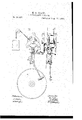
- the drawings represent a magnetic bell-striking apparatus emhodying my improvements.
- A shows a front elevation of the mechanism.
- a gear, 7: which meshes into and drives a pinion, l, on a shaft, m, which shaft has a crank-arm, n, jointed to a link, 0, the opposite end of which is jointed to an arm, 12, of the hammer-lever q, as shown in the drawings.
- the lever q swings loosely (when not locked) on a pin, r, and an arm, s, extends from the lever above the fulcrum 9', arm having a weight, (,secured to or forming part of it, this weight countcrbalancing the weight of the hammer 11
- the stress oi" the weight turns'the gear and through it the pinion, first throwing the hammer back, and then impelling it forward, (as the link is thrown down,) and as the weight of the hammcr is thus counterbalanced, onlya very slight force is necessary to throw the hammer forward against the hell.
- the pinion I may therefore he made very small relatively to the gear-wheel, thereby greatly increasing the number of blows efiected by a certain range of movement of the actuating-weight.
- the armature-bar extends back from its fulcrum d, as seen at u, the armature being held normally from the magnet l by the spring 10.
- the arm v has a tripping-mechanism for effecting the blows of the hammer through the movement of the armature, as follows:
- a spring, e may he plaeedon the arm 1), the finger slipping by the end of the spring, which then flies out and prevents back movement of the finger and crank, 'lhus,'a single rotation of the crank is effected at each breaking and closing of the circuit, and the hammer is 'securely locked from movement. excepting at each complete reciproca- 'tion of the armature, the engaging and-discngagingmeehanism being perfectly simple and efiective.
Landscapes
- Physics & Mathematics (AREA)
- Engineering & Computer Science (AREA)
- Acoustics & Sound (AREA)
- Multimedia (AREA)
- Percussive Tools And Related Accessories (AREA)
Description
M. G. CRANE. ELECTROMAGNETIC ALARM.
Patented Afig. 11, 1868.
guitar: gratis 'jate'at @ffim.
Letters Patent dVo. 80,922, dated August 11, 1868.
- mmovsnsn r metro-reenactment ALARMS.
W12 tlgciulrreierreh it ii -lipse itciicts Qiliflil nut mating wt of tlje some TO, ALL WHOM IT MAY CONCERN: I
Bev it known that I, MOSES CRANE, of Newton, in the county of Mi'ddlesex,. and State of Massachusetts, have invented an Improved Magnetic Bell-Striking ipparatus; and I do hereby declare thatft he following, taken in connection with tho drawings which accompany and form part of this specification, is a. description of my invention sufiicient to enable those skilled'in the art to practise it.
The invention relates to the construction and arrangement of the striking-mechanism of electromagnetic alarm-bells, and consists primarily in combining with the magnennnd the locking and releasing mechanism, through which, by the vibration of the armature, the bell-hammer is alternately released to be thrown against the-bell, and locked aftergiying its blow, a.counterbalanced hammer so arranged that it is thrown with aslight force to'efl'ect a quick and impulsive blow.
The drawings represent a magnetic bell-striking apparatus emhodying my improvements.
A shows a front elevation of the mechanism.
B is aside elevation thereof. p
adenotes the hell; I), the magnetic coil; 0, the armature, the shaft (1 of which is-pivotedin hearings in a frame,-e, in which frame is also mounted the winding-arborf, of a barrel, g, upon which is wound the cord h, to which the weight i is suspended. On this arborfis fixed a gear, 7:, which meshes into and drives a pinion, l, on a shaft, m, which shaft has a crank-arm, n, jointed to a link, 0, the opposite end of which is jointed to an arm, 12, of the hammer-lever q, as shown in the drawings. The lever q swings loosely (when not locked) on a pin, r, and an arm, s, extends from the lever above the fulcrum 9', arm having a weight, (,secured to or forming part of it, this weight countcrbalancing the weight of the hammer 11 When the crank it is released, the stress oi" the weight turns'the gear and through it the pinion, first throwing the hammer back, and then impelling it forward, (as the link is thrown down,) and as the weight of the hammcr is thus counterbalanced, onlya very slight force is necessary to throw the hammer forward against the hell. The pinion I may therefore he made very small relatively to the gear-wheel, thereby greatly increasing the number of blows efiected by a certain range of movement of the actuating-weight.
The armature-bar extends back from its fulcrum d, as seen at u, the armature being held normally from the magnet l by the spring 10. The arm v has a tripping-mechanism for effecting the blows of the hammer through the movement of the armature, as follows:
Two p ns, any, extend out from the arm '2: as seen at A and 13, these pins being arrangcd,-onc higher than the other, and one nearer-to tlie end of the level than the other. i
From an extension, 2, from the crank-armn, a finger-m projects, and in the normal position of the armature the pin a: is in the path of rotation of this finger, while, when the armature is drawn to the magnet, the pin is in this path of rotation, so that each pin stops the rotation of the crank, the arm e vibrating between stops ZF.
Normally the finger (IF-rests against the pin w. When the circuit isclosed, thc armature is attached to the magnet, throwing down the opposite end of -the arm 11, and allowing the finger to escape and swing past the pin :12, the finger then bringing up (the arm being still down) against the pin 3/. When the circuit is again broken, the magnet ceases to attract thearmature, and the spring draws the arm 1! up against the upper step b", carrying the pin 3 above thc'finger 11 the escaping finger and the crankth en flying round by the stress of the weight which effects the blow of the hammer, the finger bringing up again against the outer pin 2:. A spring, e, may he plaeedon the arm 1), the finger slipping by the end of the spring, which then flies out and prevents back movement of the finger and crank, 'lhus,'a single rotation of the crank is effected at each breaking and closing of the circuit, and the hammer is 'securely locked from movement. excepting at each complete reciproca- 'tion of the armature, the engaging and-discngagingmeehanism being perfectly simple and efiective.
In some firc-alarm-tclegraph systems, the circuit is kept closed, and in such a system it will be. seen that us the armature is normally held against the magnet, the finger a is normally against the stop or pin Now,
if the circuit is accidcxitally'broken, from any cause, the armature will dropirom the magnet, releasing the finger, and allowing the crank to fly nround, striking the bell once, and giving notice of the break, the finger bringing np against the outer pin 2:, and remaining there'until the circuit is again closed, \vhen'it'slips by the step :c, and brings up again against the pin 1/. v
I claim, in combination ivith the electro-magnct and its armature, the balanced hammer, connected with'thc armature-mechanism, and arranged to be operated substantially as shown and described. v
I also claim, in combination with the striking-mechanism, the stops-x 3 and finger (1- or an equivalent locking and disengaging-mechanism, substantially as described. MOSES G. GRANL.
Witnesses:
J. B. qngssy, Fnnners GGU-LD.
Publications (1)
| Publication Number | Publication Date |
|---|---|
| US80922A true US80922A (en) | 1868-08-11 |
Family
ID=2150417
Family Applications (1)
| Application Number | Title | Priority Date | Filing Date |
|---|---|---|---|
| US80922D Expired - Lifetime US80922A (en) | Improvement in electro-magsetic alaems |
Country Status (1)
| Country | Link |
|---|---|
| US (1) | US80922A (en) |
-
0
- US US80922D patent/US80922A/en not_active Expired - Lifetime
Similar Documents
| Publication | Publication Date | Title |
|---|---|---|
| US80922A (en) | Improvement in electro-magsetic alaems | |
| US482983A (en) | Edwin s | |
| US436560A (en) | Electro-mechanical gong | |
| US252175A (en) | Striking mechanism for electric bells | |
| US884663A (en) | Rotary target. | |
| US1121867A (en) | Target indicating means. | |
| US258818A (en) | Electric motor for clocks | |
| US209645A (en) | Improvement in fire-alarm telegraphs | |
| US92275A (en) | Improvement in automatic signal-boxes for fire-alarm telegraphs | |
| US426009A (en) | Bell and engine indicator for pilot-houses of steam-vessels | |
| US488388A (en) | Fire-alarm apparatus | |
| US748410A (en) | Toy. | |
| US373043A (en) | Signal for telephone-instruments | |
| US454299A (en) | Clock striking mechanism | |
| US334380A (en) | Chaeles h | |
| US191067A (en) | Improvement in burglar-alarms | |
| US1229723A (en) | Alarm apparatus. | |
| US168721A (en) | Improvement in door-bells | |
| US475526A (en) | Joseph adelard trottier | |
| US814444A (en) | Alarm-bell. | |
| US497534A (en) | Walter r | |
| US289804A (en) | Ellis s | |
| US293980A (en) | Electric gong | |
| US567577A (en) | Protective system for buildings | |
| US159369A (en) | Improvement in electric burglar-alarms |