US8092195B2 - Motor and fan apparatus having the motor - Google Patents
Motor and fan apparatus having the motor Download PDFInfo
- Publication number
- US8092195B2 US8092195B2 US12/466,404 US46640409A US8092195B2 US 8092195 B2 US8092195 B2 US 8092195B2 US 46640409 A US46640409 A US 46640409A US 8092195 B2 US8092195 B2 US 8092195B2
- Authority
- US
- United States
- Prior art keywords
- magnetic member
- stator
- center axis
- field magnet
- insulator
- Prior art date
- Legal status (The legal status is an assumption and is not a legal conclusion. Google has not performed a legal analysis and makes no representation as to the accuracy of the status listed.)
- Expired - Fee Related, expires
Links
- 239000012212 insulator Substances 0.000 claims abstract description 118
- 239000000463 material Substances 0.000 claims 2
- 230000002093 peripheral effect Effects 0.000 description 17
- 238000000034 method Methods 0.000 description 6
- 238000005452 bending Methods 0.000 description 3
- 239000000470 constituent Substances 0.000 description 3
- 239000010687 lubricating oil Substances 0.000 description 3
- 238000005520 cutting process Methods 0.000 description 2
- 229910052751 metal Inorganic materials 0.000 description 2
- 239000002184 metal Substances 0.000 description 2
- 230000000630 rising effect Effects 0.000 description 2
- 238000004804 winding Methods 0.000 description 2
- 229910000976 Electrical steel Inorganic materials 0.000 description 1
- 229910000831 Steel Inorganic materials 0.000 description 1
- HCHKCACWOHOZIP-UHFFFAOYSA-N Zinc Chemical compound [Zn] HCHKCACWOHOZIP-UHFFFAOYSA-N 0.000 description 1
- 239000000853 adhesive Substances 0.000 description 1
- 230000001070 adhesive effect Effects 0.000 description 1
- 229910052782 aluminium Inorganic materials 0.000 description 1
- XAGFODPZIPBFFR-UHFFFAOYSA-N aluminium Chemical compound [Al] XAGFODPZIPBFFR-UHFFFAOYSA-N 0.000 description 1
- 238000010276 construction Methods 0.000 description 1
- 230000003247 decreasing effect Effects 0.000 description 1
- 238000004512 die casting Methods 0.000 description 1
- 230000005489 elastic deformation Effects 0.000 description 1
- 230000014509 gene expression Effects 0.000 description 1
- 230000005484 gravity Effects 0.000 description 1
- 238000001746 injection moulding Methods 0.000 description 1
- 239000011810 insulating material Substances 0.000 description 1
- 238000009413 insulation Methods 0.000 description 1
- 238000005304 joining Methods 0.000 description 1
- 238000010030 laminating Methods 0.000 description 1
- WABPQHHGFIMREM-UHFFFAOYSA-N lead(0) Chemical compound [Pb] WABPQHHGFIMREM-UHFFFAOYSA-N 0.000 description 1
- 239000000696 magnetic material Substances 0.000 description 1
- 238000012986 modification Methods 0.000 description 1
- 230000004048 modification Effects 0.000 description 1
- 238000003825 pressing Methods 0.000 description 1
- 239000011347 resin Substances 0.000 description 1
- 229920005989 resin Polymers 0.000 description 1
- 230000000717 retained effect Effects 0.000 description 1
- 239000010959 steel Substances 0.000 description 1
- 229910052725 zinc Inorganic materials 0.000 description 1
- 239000011701 zinc Substances 0.000 description 1
Images


Classifications
-
- F—MECHANICAL ENGINEERING; LIGHTING; HEATING; WEAPONS; BLASTING
- F04—POSITIVE - DISPLACEMENT MACHINES FOR LIQUIDS; PUMPS FOR LIQUIDS OR ELASTIC FLUIDS
- F04D—NON-POSITIVE-DISPLACEMENT PUMPS
- F04D25/00—Pumping installations or systems
- F04D25/02—Units comprising pumps and their driving means
- F04D25/06—Units comprising pumps and their driving means the pump being electrically driven
- F04D25/0606—Units comprising pumps and their driving means the pump being electrically driven the electric motor being specially adapted for integration in the pump
- F04D25/0613—Units comprising pumps and their driving means the pump being electrically driven the electric motor being specially adapted for integration in the pump the electric motor being of the inside-out type, i.e. the rotor is arranged radially outside a central stator
- F04D25/0633—Details of the magnetic circuit
-
- F—MECHANICAL ENGINEERING; LIGHTING; HEATING; WEAPONS; BLASTING
- F04—POSITIVE - DISPLACEMENT MACHINES FOR LIQUIDS; PUMPS FOR LIQUIDS OR ELASTIC FLUIDS
- F04D—NON-POSITIVE-DISPLACEMENT PUMPS
- F04D25/00—Pumping installations or systems
- F04D25/02—Units comprising pumps and their driving means
- F04D25/06—Units comprising pumps and their driving means the pump being electrically driven
- F04D25/0606—Units comprising pumps and their driving means the pump being electrically driven the electric motor being specially adapted for integration in the pump
- F04D25/0613—Units comprising pumps and their driving means the pump being electrically driven the electric motor being specially adapted for integration in the pump the electric motor being of the inside-out type, i.e. the rotor is arranged radially outside a central stator
- F04D25/0646—Details of the stator
-
- F—MECHANICAL ENGINEERING; LIGHTING; HEATING; WEAPONS; BLASTING
- F04—POSITIVE - DISPLACEMENT MACHINES FOR LIQUIDS; PUMPS FOR LIQUIDS OR ELASTIC FLUIDS
- F04D—NON-POSITIVE-DISPLACEMENT PUMPS
- F04D29/00—Details, component parts, or accessories
- F04D29/60—Mounting; Assembling; Disassembling
- F04D29/64—Mounting; Assembling; Disassembling of axial pumps
- F04D29/644—Mounting; Assembling; Disassembling of axial pumps especially adapted for elastic fluid pumps
- F04D29/646—Mounting or removal of fans
-
- H—ELECTRICITY
- H02—GENERATION; CONVERSION OR DISTRIBUTION OF ELECTRIC POWER
- H02K—DYNAMO-ELECTRIC MACHINES
- H02K1/00—Details of the magnetic circuit
- H02K1/06—Details of the magnetic circuit characterised by the shape, form or construction
- H02K1/12—Stationary parts of the magnetic circuit
- H02K1/18—Means for mounting or fastening magnetic stationary parts on to, or to, the stator structures
- H02K1/187—Means for mounting or fastening magnetic stationary parts on to, or to, the stator structures to inner stators
-
- H—ELECTRICITY
- H02—GENERATION; CONVERSION OR DISTRIBUTION OF ELECTRIC POWER
- H02K—DYNAMO-ELECTRIC MACHINES
- H02K5/00—Casings; Enclosures; Supports
- H02K5/04—Casings or enclosures characterised by the shape, form or construction thereof
- H02K5/16—Means for supporting bearings, e.g. insulating supports or means for fitting bearings in the bearing-shields
- H02K5/163—Means for supporting bearings, e.g. insulating supports or means for fitting bearings in the bearing-shields radially supporting the rotary shaft at only one end of the rotor
-
- F—MECHANICAL ENGINEERING; LIGHTING; HEATING; WEAPONS; BLASTING
- F05—INDEXING SCHEMES RELATING TO ENGINES OR PUMPS IN VARIOUS SUBCLASSES OF CLASSES F01-F04
- F05D—INDEXING SCHEME FOR ASPECTS RELATING TO NON-POSITIVE-DISPLACEMENT MACHINES OR ENGINES, GAS-TURBINES OR JET-PROPULSION PLANTS
- F05D2260/00—Function
- F05D2260/30—Retaining components in desired mutual position
- F05D2260/36—Retaining components in desired mutual position by a form fit connection, e.g. by interlocking
-
- H—ELECTRICITY
- H02—GENERATION; CONVERSION OR DISTRIBUTION OF ELECTRIC POWER
- H02K—DYNAMO-ELECTRIC MACHINES
- H02K1/00—Details of the magnetic circuit
- H02K1/06—Details of the magnetic circuit characterised by the shape, form or construction
- H02K1/12—Stationary parts of the magnetic circuit
- H02K1/14—Stator cores with salient poles
- H02K1/146—Stator cores with salient poles consisting of a generally annular yoke with salient poles
-
- H—ELECTRICITY
- H02—GENERATION; CONVERSION OR DISTRIBUTION OF ELECTRIC POWER
- H02K—DYNAMO-ELECTRIC MACHINES
- H02K2211/00—Specific aspects not provided for in the other groups of this subclass relating to measuring or protective devices or electric components
- H02K2211/03—Machines characterised by circuit boards, e.g. pcb
-
- H—ELECTRICITY
- H02—GENERATION; CONVERSION OR DISTRIBUTION OF ELECTRIC POWER
- H02K—DYNAMO-ELECTRIC MACHINES
- H02K7/00—Arrangements for handling mechanical energy structurally associated with dynamo-electric machines, e.g. structural association with mechanical driving motors or auxiliary dynamo-electric machines
- H02K7/08—Structural association with bearings
- H02K7/09—Structural association with bearings with magnetic bearings
-
- H—ELECTRICITY
- H02—GENERATION; CONVERSION OR DISTRIBUTION OF ELECTRIC POWER
- H02K—DYNAMO-ELECTRIC MACHINES
- H02K7/00—Arrangements for handling mechanical energy structurally associated with dynamo-electric machines, e.g. structural association with mechanical driving motors or auxiliary dynamo-electric machines
- H02K7/14—Structural association with mechanical loads, e.g. with hand-held machine tools or fans
Definitions
- the present invention relates to an electric motor, and more specifically to a fan apparatus having the electric motor.
- some motors in fan apparatuses are constructed such that a rotor portion is attracted to a stator portion by using a magnetic attractive force in order to restrict rising of the rotor portion and an impeller relative to the stator portion during rotation.
- the motor is provided with an attracting magnet which contacts a tip end of a shaft or a magnetic member which faces a field magnet in a direction parallel to the center axis.
- the magnetic member is fixed to the stator portion by various techniques.
- an annular printed wiring board is attached around a bushing into which a shaft is inserted, and an attracting member having a substantially annular shape for magnetically attracting a permanent magnet is attached on the top side (i.e., on the side toward a rotor) of the printed wiring board.
- a stator yoke having four standing portions which protrude upwardly from its outer circumference is further provided on the attracting member. Since these standing portions face a lower portion of the permanent magnet of the rotor in a direction perpendicular to the center axis, the permanent magnet is also attracted to the stator yoke to perform stable rotation of the rotor.
- annular portion of the balancing portion is fixed around a cylindrical portion of a base into which a shaft is inserted.
- Four magnetic surfaces which extend from the outer circumference of the annular portion toward a rotor, face an annular magnet of the rotor in a radial direction.
- a balancing sheet having an opening formed in its center is attached around a cylindrical portion which is provided on an opposite end surface of a stator to a rotor.
- the balancing sheet and a permanent magnet of the rotor face each other in a direction parallel to the center axis.
- the balancing sheet and a core of the stator are formed as one member.
- the magnetic attractive force generated between the magnetic member and the field magnet should be increased when compared with a small-sized fan or a fan having a low rotation speed, in order to prevent rising of the rotor portion relative to the stator portion.
- preferred embodiments of the present invention easily locate a flat portion of a magnetic member close to the field magnet, wherein the magnetic member generates a magnetic attractive force between a field magnet and the magnetic member in the direction parallel or substantially parallel to the center axis.
- An electric motor includes a stator portion, a rotor portion arranged to rotate about a center axis, and a bearing mechanism arranged to rotatably support the rotor portion relatively to the stator portion, wherein the rotor portion includes a rotor holder having a substantially cylindrical shape with a closed end, and a field magnet fixed to an inner circumference of the rotor holder; the stator portion includes a stator which is disposed inside the rotor holder and arranged to generate a torque between the field magnet and the stator, a base portion located below the rotor holder, the stator being either directly or indirectly fixed to the base portion, and a magnetic member which is positioned between the field magnet and the base portion and generates a magnetic attractive force between the field magnet and the magnetic member; and the magnetic member includes a cylindrical portion having a substantially cylindrical shape into which a lower end portion of an insulator of the stator is inserted, the lower end portion being a portion of an outer portion of
- the lower end portion of the insulator is inserted into the cylindrical portion of the magnetic member, it is possible to easily locate the flat portion of the magnetic member close to the field magnet.
- FIG. 1 is a cross-sectional view of an axial fan according to a first preferred embodiment of the present invention.
- FIG. 2 is a bottom view of a lower insulator according to the first preferred embodiment of the present invention.
- FIG. 3 is a cross-sectional view of the lower insulator.
- FIG. 4 is a plan view of a magnetic member according to the first preferred embodiment of the present invention.
- FIG. 5 is a cross-sectional view of the magnetic member.
- FIG. 6 is an enlarged view showing a portion of the magnetic member.
- FIG. 7 is a cross-sectional view of a stator and the magnetic member.
- FIG. 8 is a plan view of a base portion according to the first preferred embodiment of the present invention t.
- FIG. 9 is a cross-sectional view of a protrusion of the base portion.
- FIG. 10 is a cross-sectional view of another protrusion of the base portion.
- FIG. 11 is a cross-sectional view of the protrusion of the base portion and a flat portion of the magnetic member.
- FIG. 12 is a cross-sectional view of the stator and the magnetic member.
- FIG. 13 is a view showing a state where the stator is fixed to a sleeve portion.
- FIG. 14 is a cross-sectional view of the protrusion of the base portion and the flat portion of the magnetic member.
- FIG. 15 is a plan view showing another example of the magnetic member.
- FIG. 16 is a plan view showing still another example of the magnetic member.
- FIG. 17 is a partial sectional view of the motor.
- FIG. 18 is a bottom view of a tooth covering portion.
- FIG. 19 is a perspective view of a stator, a printed wiring board, and a magnetic member according to a second preferred embodiment of the present invention.
- FIG. 20 is a perspective view of a stator.
- FIG. 21 is a cross-sectional view of the printed wiring board and the magnetic member.
- FIG. 22 is a cross-sectional view of the stator, the printed wiring board, and the magnetic member.
- FIG. 23 is a plan view of a magnetic member in an axial fan according to a third preferred embodiment of the present invention.
- FIG. 24 is a bottom view of a lower insulator.
- FIG. 25 is a cross-sectional view of the lower insulator.
- FIG. 26 is a plan view of the lower insulator to which the magnetic member is fixed.
- FIG. 27 is a cross-sectional view of the lower insulator and the magnetic member.
- FIG. 28 is a view showing a slit of the magnetic member when viewed from the outside in a radial direction.
- FIG. 29 is a view showing a small protrusion of the lower insulator and the slit of the magnetic member when viewed from the outside in the radial direction.
- FIG. 30 is a cross-sectional view of the lower insulator and the magnetic member.
- FIG. 31 is a view showing the small protrusion and the magnetic member when viewed from the outside in the radial direction.
- FIG. 32 is a cross-sectional view of a motor according to another example.
- FIG. 33 is a cross-sectional view of a motor according to still another example.
- FIG. 34 is a cross-sectional view of a motor according to still another example.
- the upper side in a direction of the center axis J 1 in drawing is simply referred to as “upper side”, and the lower side in drawing is simply referred to as “lower side”.
- the expressions of the “upper side” and the “lower side” do not necessarily coincide with the upper side and the lower side in the direction of gravity.
- FIG. 1 is a longitudinal sectional view of an axial fan 1 which is a fan apparatus according to the first preferred embodiment of the present invention.
- the axial fan 1 has a motor 12 (for example, an electric single phase motor), a plurality of blades 11 , a housing 13 surrounding the motor 12 , and a plurality of supporting ribs 14 .
- the housing 13 is connected to the motor 12 through the supporting ribs 14 .
- the plurality of blades 11 are fixed to a rotor portion 121 of the motor 12 such that the plurality of supporting ribs 14 are arranged to support the motor 12 .
- the housing 13 and the supporting ribs 14 are preferably formed as a single member by, for example, injection molding with a resin or plastic. Alternatively, the housing 13 and the supporting ribs 14 may also be formed as a single member through aluminum die-casting. In FIG. 1 , the outlines of the blades 11 and the supporting ribs 14 are shown on the right and left sides of the center axis J 1 for convenience of illustration.
- the motor 12 has a rotor portion 121 which is a rotating body, a stator portion 122 which is a fixed body, and a sleeve portion 123 which has a substantially cylindrical shape with a bottom and is fixed to the stator portion 122 .
- the rotor portion 121 is located on the upper side of the stator portion 122 along the center axis J 1 in the motor 12 .
- the rotor portion 121 preferably has a rotor holder 1211 having a substantially cylindrical shape with a closed end, a yoke 1212 made from metal, a field magnet 1213 having a substantially cylindrical shape, and a shaft 1214 .
- the yoke 1212 made from metal preferably has a cylindrical shape centered about the center axis J 1 .
- the substantially cylindrical-field magnet 1213 is fixed to an inner circumference of the rotor holder 1211 such that the yoke 1212 is sandwiched between the rotor holder 1211 and the substantially cylindrical-field magnet 1213 .
- the shaft 1214 projects downwardly from the center portion of a lid portion 1211 a of the rotor holder 1211 .
- the plurality of blades 11 protrude outwardly in a radial direction from the outer circumference of the rotor holder 1211 .
- the stator portion 122 preferably has a base portion 1221 having a substantially annular shape, a stator 1222 , a printed wiring board 1223 having a substantially annular shape, and a magnetic member 1224 having a substantially annular shape.
- the sleeve portion 123 is fixed to the center opening of the substantially annular base portion 1221 .
- the stator 1222 is attached to an outer circumferential surface of the sleeve portion 123 .
- the substantially annular-printed wiring board 1223 is preferably disposed below the stator 1222 .
- the substantially annular-magnetic member 1224 is positioned between the field magnet 1213 of the rotor portion 121 and the printed wiring board 1223 .
- the base portion 1221 is located below the rotor holder 1211 .
- the base portion 1221 is located on the opposite side of the rotor holder 1211 from the side of a lid portion 1211 a .
- the stator 1222 is fixed to the base portion 1221 indirectly via the sleeve portion 123 .
- the stator 1222 preferably has a stator core 41 , an upper insulator 42 , a lower insulator 43 , and coils 44 .
- the stator core 41 is formed by laminating thin plates of silicon steel.
- the upper insulator 42 and the lower insulator 43 cover the upper portion and the lower portion of the stator core 41 .
- the coils 44 are preferably formed by winding conductive wires onto the upper insulator 42 and the lower insulator 43 .
- the stator 1222 is positioned inside the rotor holder 1211 to oppose the field magnet 1213 in the radial direction.
- stator 1222 When a current is applied from an external power source (not shown) to the stator 1222 through the printed wiring board 1223 , the stator 1222 is arranged to produce a magnetic field to generate a torque around the center axis J 1 between the stator 1222 and the field magnet 1213 .
- the sleeve portion 123 preferably has a sleeve 1231 , a sleeve housing 1232 , and a thrust plate 1233 .
- the sleeve 1231 preferably has a substantially cylindrical shape that is centered about the center axis J 1 .
- the sleeve housing 1232 is arranged to cover an outer circumferential surface and a lower portion of the sleeve 1231 and has a substantially cylindrical shape with a bottom.
- the thrust plate 1233 is disposed on an inner bottom surface of the sleeve housing 1232 .
- the shaft 1214 of the rotor portion 121 is inserted into the sleeve 1231 , and a lower end of the shaft 1214 is arranged to contact the thrust plate 1233 .
- the sleeve 1231 preferably is impregnated with lubricating oil, for example, and the lubricating oil is retained in the sleeve portion 123 by the sleeve housing 1232 .
- the sleeve 1231 , the sleeve housing 1232 , the thrust plate 1233 , the shaft 1214 , and the lubricating oil define a bearing mechanism 120 in the motor 12 .
- the rotor portion 121 is rotatably supported relatively to the stator portion 122 in the motor 12 .
- the rotor portion 121 is arranged to rotate around the stator 1222 about the center axis J 1 such that the blades 11 which protrude outwardly in the radial direction from the rotor portion 121 generate an air flow in the direction of the center axis J 1 from the upper side toward the lower side of FIG. 1 .
- the lower end of the shaft 1214 is preferably in continuous contact with the thrust plate 1233 due to a magnetic attractive force generated between the magnetic member 1224 and the field magnet 1213 in the axial fan 1 .
- the relative position in the direction of the center axis J 1 between the rotor portion 121 and the stator portion 122 is fixed in the axial fan 1 .
- the axial fan 1 since the axial fan 1 has the above-described arrangement, it is possible to stably rotate the motor 12 while avoiding excessive contact thus minimizing noise and damage.
- FIG. 2 is a bottom view of the lower insulator 43 , in which the outline of the stator core 41 is represented by two-dot chain lines.
- FIG. 3 is a cross-sectional view of the lower insulator 43 at the positions indicated by arrows A in FIG. 2 .
- the stator core 41 has a center portion 411 having a substantially cylindrical shape and four, for example, T-shaped tooth portions 412 which extend outwardly in the radial direction with respect to the center axis J 1 from the outer circumference of the center portion 411 , wherein outer end portions of the tooth portions 412 spread in the both sides in a circumferential direction.
- the lower insulator 43 has an annular portion 431 which overlaps with the center portion 411 of the stator core 41 in the direction parallel or substantially parallel to the center axis J 1 and four, for example, tooth covering portions 432 arranged to cover the tooth portions 412 .
- the tooth portion 412 slightly protrude to the outside of the tooth covering portion 432 in the radial direction.
- the annular portion 431 is provided with four, for example, protrusions 4311 which extend downwardly at connected positions of the tooth covering portions 432 and four, for example, pin inserting portions 4312 protruding outwardly in the radial direction from an outer circumferential surface of the annular portion 431 .
- the pin inserting portion 4312 is arranged to extend upwardly from the annular portion 431 in parallel or substantially in parallel with the center axis J 1 , and a pin 45 is inserted into the pin inserting portion 4312 as shown in FIG. 1 .
- An upper end of the pin 45 is connected to a lead wire (not shown) of a coil which is wound around the stator core 41 , and a lower end of the pin 45 is inserted into a hole defined in the printed wiring board 1223 and connected to an opposite surface of the printed wiring board 1223 to the stator 1222 , that is, a lower surface of the printed wiring board 1223 .
- protrusions 4321 which protrude toward the base portion 1221 (see FIG. 1 ) and have a bar shape are provided in the center positions of tip ends of the four tooth covering portions 432 .
- a tip end 4321 a of the protrusion 4321 protrudes outwardly in the radial direction.
- two protrusions 4322 extending downwardly are provided on the both sides in the circumferential direction of the protrusion 4321 .
- the protrusion 4311 of the annular portion 431 and the tip end 4321 a of the protrusion 4321 are in contact with an inner circumferential surface and an upper surface of the printed wiring board 1223 , respectively, to determine the relative position between the printed wiring board 1223 and the lower insulator 43 .
- the printed wiring board 1223 and the lower insulator 43 are fixed by connecting the printed wiring board 1223 and the pins 45 inserted in the pin inserting portions 4312 .
- FIG. 4 is a plan view showing the magnetic member 1224 , together with the printed wiring board 1223 located below the magnetic member 1224 .
- FIG. 5 is a cross-sectional view of the magnetic member 1224 at the positions indicated by arrows B in FIG. 4 .
- the cross-section of the magnetic member 1224 defined by a plane including the center axis J 1 has an L-shape in the circumferential direction.
- the magnetic member 1224 is preferably formed by press working easily at low cost. Specifically, magnetic material such as a zinc plated steel sheet is preferably punched out as one annular plate, and the plate is bent by deep drawing so that the inner portion is bent parallel to the center axis J 1 to form the magnetic member 1224 .
- the magnetic member 1224 has a cylindrical portion 51 having a substantially cylindrical shape and extending in parallel or substantially parallel with the center axis J 1 and a flat portion 52 having a substantially annular shape which spreads outwardly in the radial direction with respect to the center axis J 1 from the lower end of the cylindrical portion 51 .
- the cylindrical portion 51 opposes a lower portion of an inner circumferential surface of the field magnet 1213 in the direction perpendicular or substantially perpendicular to the center axis J 1 .
- the flat portion 52 opposes a lower edge of the field magnet 1213 in the direction parallel or substantially parallel to the center axis J 1 .
- the flat portion 52 preferably has one notch 521 which is formed by cutting out a portion of the inner portion.
- the cylindrical portion 51 is removed from the upper end to the lower end in parallel or substantially in parallel with the center axis J 1 .
- Small holes 53 are preferably defined at a lower portion of the cylindrical portion 51 and an inner portion of the flat portion 52 , and the holes 53 are preferably cut out at regular intervals in the circumferential direction with respect to the center axis J 1 .
- FIG. 6 is a view showing the vicinity of the hole 53 which is viewed from the outside in the radial direction.
- the hole 53 is preferably substantially U-shaped in which two upper portions extend separately, and a portion located in the substantially U-shaped hole 53 in the circumferential direction is a convex portion 511 which projects downwardly in the cylindrical portion 51 .
- a hall element 8 is preferably provided on the printed wiring board 1223 and the hall element 8 and notch 521 are preferably positioned as to overlap with each other in the direction parallel or substantially parallel to the center axis J 1 .
- the hall element 8 opposes the field magnet 1213 (see FIG. 1 ) through the notch 521 .
- the hall element 8 can detect the magnetic field of the field magnet 1213 without influences of the magnetic member 1224 to detect the rotation position of the field magnet 1213 .
- the printed wiring board 1223 is provided with the notch 521 , a portion between magnetic poles of the field magnet 1213 is preferably positioned at the notch 521 during stopping of the motor 12 .
- a stopping position in the circumferential direction of the rotor portion 121 becomes a specific position to thereby prevent startup errors of the motor 12 .
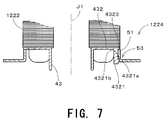
- FIG. 7 is an enlarged view of the stator 1222 and the magnetic member 1224 .
- a protrusion 4321 provided in the lower insulator 43 of the stator 1222 is inserted into the cylindrical portion 51 of the magnetic member 1224 , and the cylindrical portion 51 contacts outer surfaces of the protrusion 4321 .
- the tip end 4321 a of the protrusion 4321 is positioned in the hole 53 of the magnetic member 1224 and engaged with the hole 53 in the circumferential direction.
- the orientation of the magnetic member 1224 in the circumferential direction relative to the lower insulator 43 is fixed.
- An upper surface 4321 b of the tip end 4321 a contacts the tip end of the convex portion 511 shown in FIG. 6 , and an outer peripheral portion 4323 of the tooth covering portion 432 contacts the upper end of the cylindrical portion 51 around the whole circumference. That is to say, the tip end 4321 a of the protrusion 4321 and the outer peripheral portion 4323 of the tooth covering portion 432 are engaged with the cylindrical portion 51 of the magnetic member 1224 in the direction parallel to the center axis J 1 . With this engagement, the position of the magnetic member 1224 relative to the lower insulator 43 in the direction of the center axis J 1 is fixed.
- FIG. 8 is a plan view of the base portion 1221
- FIGS. 9 and 10 are cross-sectional views of the base portion 1221 at the positions indicated by arrows C and D in FIG. 8 .
- the base portion 1221 preferably has four, for example, protrusions 61 which are arranged at regular intervals inside an outer side wall 1221 a that extends in the circumferential direction, and which extend in parallel or substantially in parallel with the center axis J 1 .
- a tip end 611 of the protrusion 61 protrudes inwardly in the radial direction slightly.
- two auxiliary protrusions 62 are provided on the both sides in the circumferential direction of the protrusion 61 .
- FIG. 11 is a cross-sectional view showing a state where the flat portion 52 of the magnetic member 1224 is fitted with the protrusion 61 , together with the auxiliary protrusion 62 .
- the protrusion 61 is located outside the flat portion 52
- the auxiliary protrusion 62 is located below an outer peripheral portion 522 of the flat portion 52 .
- the tip end 611 of the protrusion 61 is located above a tip end 621 of the auxiliary protrusion 62 .
- the distance between a lower surface 6111 of the tip end 611 of the protrusion 61 and the upper surface 6211 of the tip end 621 of the auxiliary protrusion 62 in the direction parallel or substantially parallel to the center axis J 1 see FIG.
- the flat portion 52 is made almost equal to the thickness of the flat portion 52 .
- the upper surface of the flat portion 52 contacts the lower surface 6111 of the tip end 611 of the protrusion 61 .
- the flat portion 52 is fixed to the base portion 1221 by engaging the flat portion 52 with the protrusion 61 in the direction parallel or substantially parallel to the center axis J 1 in the motor 12 .
- the lower surface of the flat portion 52 and the upper surface 6211 of the auxiliary protrusion 62 are arranged slightly apart from each other.
- the cylindrical portion 51 of the magnetic member 1224 contacts the outer surfaces of the protrusions 4321 of the lower insulator 43 .
- the cylindrical portion 51 and the flat portion 52 are engaged with the tip ends 4321 a of the protrusions 4321 of the lower insulator 43 and the protrusions 61 of the base portion 1221 , respectively, in the direction parallel or substantially parallel to the center axis J 1 .
- the position of the magnetic member 1224 in the stator portion 122 is fixed.
- the upper insulator 42 (see FIG. 1 ) and the lower insulator 43 shown in FIG. 2 are attached to the stator core 41 , conductive wires are wound around the stator core 41 together with both insulators, and the stator 1222 (see FIG. 1 ) is prepared in advance.
- the magnetic member 1224 shown in FIG. 4 is disposed below the lower insulator 43 so that the holes 53 coincide with the protrusions 4321 of the lower insulator 43 in the direction parallel or substantially parallel to the center axis J 1 .
- the protrusions 4321 of the lower insulator 43 are inserted into the cylindrical portion 51 of the magnetic member 1224 .
- the tip ends 4321 a of the protrusions 4321 contact an upper portion of the cylindrical portion 51 of the magnetic member 1224 and the protrusions 4321 are elastically deformed inwardly in the radial direction.
- the tip ends 4321 a press the convex portions 511 of the cylindrical portion 51 shown in FIG. 6 , and then the convex portions 511 are elastically deformed outwardly in the radial direction with respect to the center axis J 1 (toward the front side when viewed on the paper in FIG. 6 ).
- the convex portions 511 and the protrusions 4321 return to the original positions.
- the tip ends 4321 a of the protrusions 4321 are engaged with the holes 53 of the magnetic member 1224 in the direction parallel to the center axis J 1 .
- the cylindrical portion 51 contacts the outer surfaces of the protrusions 4321 of the lower insulator 43 .
- the upper end of the cylindrical portion 51 contacts the outer peripheral portions 4323 of the tooth covering portions 432 .
- An operation for fitting the magnetic member 1224 to the lower insulator 43 is preferably performed after the conductive wires are wound around the stator core 41 to form coils. Therefore, the operation process is not complicated.
- the stator 1222 and the magnetic member 1224 are vertically inversed from the state shown in FIG. 7 , and the printed wiring board 1223 (see FIG. 1 ) is put on the lower insulator 43 from the upper side. As shown in FIG. 4 , the hall element 8 and the notch 521 of the magnetic member 1224 oppose each other in the direction parallel or substantially parallel to the center axis J 1 .
- the pins 45 (see FIG. 1 ) of the stator 122 are inserted into holes 1223 a of the printed wiring board 1223 .
- the printed wiring board 1223 and the lower insulator 43 are fixed.
- the fitting direction of the printed wiring board 1223 in the direction perpendicular or substantially perpendicular to the center axis J 1 that is, the orientation of the printed wiring board 1223 in the circumferential direction, is easily determined by using the notch 521 of the magnetic member 1224 as a mark.
- the sleeve portion 123 is fixed to an opening of the base portion 1221 which is prepared separately.
- An assembly of the stator 1222 , the printed wiring board 1223 , and the magnetic member 1224 and the base portion 1221 which is fixed to the sleeve portion 123 are disposed to oppose each other with their center axes J 1 coinciding with one another. Then, the sleeve portion 123 is inserted into the stator 1222 , the printed wiring board 1223 , and the magnetic member 1224 along the center axis J 1 .
- the flat portion 52 is pressed downwardly, and the outer peripheral portion 522 contacts the tip ends 611 of the protrusions 61 of the base portion 1221 to elastically deform the protrusions 61 to move the protrusions 61 outwardly in the radial direction. Further, the flat portion 52 contacts the tip ends 621 of the auxiliary protrusions 62 by pressing the flat portion 52 downwardly, and the protrusions 61 return to the original positions.
- the positions of the outer peripheral portion 522 of the flat portion 52 in the direction of the center axis J 1 are fixed relatively to the base portion 1221 .
- stator 1222 and the sleeve housing 1232 shown in FIG. 13 are fixed by, for example, press fitting and adhesive.
- the protrusions 4321 of the lower insulator 43 are inserted into the cylindrical portion 51 of the magnetic member 1224 . Therefore, the position of the magnetic member 1224 in the direction of the center axis J 1 can be easily altered without largely changing the shape of the lower insulator 43 . As a result, it is possible to easily locate the flat portion 52 of the magnetic member 1224 close to the field magnet 1213 .
- the magnetic member 1224 can be stably fitted with the lower insulator 43 by the protrusions 4321 through a simple structure. Since the cylindrical portion 51 contacts the outer surfaces of the protrusions 4321 , it is possible to easily keep the flat portion 52 horizontally, that is, perpendicular or substantially perpendicular to the center axis J 1 , while the center axis of the magnetic member 1224 appropriately coincides with the center axis J 1 of the motor 12 .
- the tip ends 4321 a of the protrusions 4321 and the outer peripheral portions 4323 of the tooth covering portions 432 are engaged with the holes 53 and the upper end of the cylindrical portion 51 , respectively, in the direction parallel or substantially parallel to the center axis J 1 .
- the position of the magnetic member 1224 in the direction parallel or substantially parallel to the center axis J 1 is fixed easily. Since the protrusions 61 of the base portion 1221 are engaged with the flat portion 52 in the direction parallel or substantially parallel to the center axis J 1 , the magnetic member 1224 is more stably fixed.
- the four hall portions 53 of the magnetic member 1224 are preferably small, and therefore an influence of the holes 53 on the magnetic attractive force generated between the field magnet 1213 and the magnetic member 1224 is small. Since the number of notches or holes provided in the magnetic member 1224 is preferably one (i.e., only the notch 521 ), the large area of the magnetic member 1224 can be maintained.
- the notch 521 shown in FIG. 4 may be a slit which is elongated in the radial direction as long as the width in the circumferential direction of the notch 521 is made larger than that of the hall element 8 .
- FIG. 15 is a plan view showing another example of the magnetic member 1224 , together with the printed wiring board 1223 which is located below the magnetic member 1224 .
- the magnetic member 1224 shown in FIG. 15 is substantially C-shaped in plan view.
- a notch 521 a is arranged to cut across the flat portion 52 outwardly in the radial direction with respect to the center axis J 1 .
- a portion of the cylindrical portion 51 is removed from the upper end to the lower end in parallel with the center axis J 1 .
- the hall element 8 is disposed as to overlap with the field magnet 1213 (see FIG. 1 ) through the notch 521 a in the direction parallel or substantially parallel to the center axis J 1 .
- the other aspects of the magnetic member 1224 shown in FIG. 15 are preferably the same as that shown in FIG. 4 .
- the number of the notch 521 a provided in the flat portion 52 may be (substantially) one. Thus, it is possible to decrease a loss of magnetic attractive force generated between the field magnet 1213 and the magnetic member 1224 .
- FIG. 16 is a plan view showing still another preferred embodiment of the magnetic member 1224 .
- FIG. 17 is a longitudinal cross-sectional view showing a state where the magnetic member 1224 shown in FIG. 16 is fitted with the lower insulator 43 and the base portion 1221 .
- FIG. 17 also shows a portion of the back of the cross-section.
- a motor in which the magnetic member 1224 of FIG. 16 is provided is the same as the motor 12 of FIG. 1 excluding that the shapes of the magnetic member 1224 , the lower insulator 43 , and the base portion 1221 are slightly different from those of the motor 12 , and the same reference signs are given to the corresponding constituent elements.
- a convex portion 511 of the cylindrical portion 51 is gradually tilted so that its lower portion gets closer to the center axis J 1 in the magnetic member 1224 .
- a bent portion 525 is provided which is bent to be inclined downwardly and outwardly in the radial direction and has a flat tip end.
- a large notch 521 is provided in the flat portion 52 .
- the tip end of the bent portion 525 contacts the upper surface of the printed wiring board 1223 .
- the tip end of the bent portion 525 and an outer peripheral portion of the printed wiring board 1223 are fixed between the tip end 611 of the protrusion 61 of the base portion 1221 and the auxiliary protrusions 62 .
- FIG. 18 is a bottom view showing one tooth covering portion 432 in the lower insulator 43 .
- an outer circumferential surface 4321 c of the protrusion 4321 which protrudes downwardly from the vicinity of a tip end of the tooth covering portion 432 , is made slightly closer to the center axis J 1 when compared with that shown in FIGS. 2 and 7 .
- the cylindrical portion 51 of the magnetic member 1224 only contacts outer surfaces of the protrusions 4322 provided on the both sides of the protrusion 4321 .
- the convex portion 511 of the cylindrical portion 51 is preferably tilted and the outer circumferential surface 4321 c of the protrusion 4321 of the lower insulator 43 is made close to the center axis J 1 .
- the lower insulator 43 is inserted into the cylindrical portion 51 while the protrusions 4321 are hardly elastically deformed and only the convex portions 511 are elastically deformed.
- the tip ends of the convex portions 511 move to positions which are closer to the center axis J 1 than those of the tip ends 4321 a of the protrusions 4321 , and the position of the magnetic member 1224 in the direction of the center axis J 1 is fixed.
- the lower insulator 43 After the lower insulator 43 is completely inserted into the cylindrical portion 51 , the tip ends of the convex portions 511 move to positions which are closer to the center axis J 1 than those of the tip ends 4321 a of the protrusions 4321 , and the position of the magnetic member 1224 in the direction of the center axis J 1 is fixed.
- the protrusion 4321 is designed to be shorter than the protrusions 4322 , the upper surface of the printed wiring board 1223 contacts the lower end of the protrusions 4322 without contacting the protrusion 4321 .
- the strength of the lower insulator 43 relative to the force inflicted by the printed wiring board 1223 during assembly can be ensured by the design of the thickness of the protrusions 4322 .
- the protrusion 4321 can be easily elastically deformed and the cylindrical portion 51 can be locked. That is to say, it is possible to design the lower insulator 43 easily by separating the function of the protrusion 4321 and the function of the protrusions 4322 in the lower insulator 43 .
- the protrusions 4321 of the lower insulator 43 are inserted into the cylindrical portion 51 of the magnetic member 1224 . Therefore, it is possible to easily locate the flat portion 52 of the magnetic member 1224 close to the field magnet 1213 .
- the magnetic member 1224 can be stably fitted with the lower insulator 43 by the protrusions 4321 with a simple structure, and the flat portion 52 can be easily kept horizontally while the center axis of the magnetic member 1224 is made to appropriately coincide with the center axis J 1 of the motor 12 . Since the number of the notch or the hole provided in the magnetic member 1224 may be substantially one (i.e., only one notch 521 ), the large area of the magnetic member 1224 can be maintained.
- FIG. 19 is a perspective view showing a stator 1222 , a magnetic member 1224 a , and a printed wiring board 1223 of an axial fan according to the second preferred embodiment.
- FIG. 20 is a perspective view of the stator 1222 . In FIGS. 19 and 20 , the shape of an upper insulator 42 of the stator 1222 is drawn simply.
- pairs of lug portions 523 are preferably provided at four positions in the circumferential direction in the outer circumference of the flat portion 52 at regular intervals in the magnetic member 1224 a .
- the holes 53 shown in FIG. 4 are omitted in the magnetic member 1224 a .
- One notch 521 is defined in the flat portion 52 , and a portion of a lower end portion of the cylindrical portion 51 is cut out at the position where the notch 521 is provided.
- the rest of the magnetic member 1224 a is the same as that of the magnetic member 1224 , and the same reference signs are given to the same constituent elements.
- plate-shaped protrusions 4324 are provided in the lower insulator 43 a of the stator 1222 .
- the protrusions 4324 protrude downwardly from tip ends of four tooth portions 412 , that is, protrude toward the base portion 1221 (see FIG. 1 ).
- Other construction of the lower insulator 43 a is the same as that of the lower insulator 43 of FIG. 3 .
- the tooth portions 412 slightly protrude to the outside of the lower insulator 43 a in the radial direction.
- the protrusions 4324 of the lower insulator 43 a shown in FIG. 20 are inserted into the cylindrical portion 51 of the magnetic member 1224 a shown in FIG. 19 , and the cylindrical portion 51 contacts outer surfaces of the protrusions 4324 .
- the flat portion 52 of the magnetic member 1224 a is preferably fixed to the printed wiring board 1223 by bending the lug portions 523 inwardly from the outer peripheral portion of the printed wiring board 1223 .
- FIG. 19 shows the lug portions 523 before bending. Insulating material such as insulating film, for example, is provided on the printed wiring board 1223 , and the insulation between the magnetic member 1224 a and the printed wiring board 1223 is secured. On the printed wiring board 1223 , the hall element 8 is attached to the position corresponding to the notch 521 of the flat portion 52 . The hall element 8 opposes the field magnet 1213 (see FIG. 1 ) of the rotor portion 121 through the notch 521 .
- Insulating material such as insulating film, for example
- stator 1222 is fixed to the outer circumference of the sleeve housing 1232 , and the printed wiring board 1223 is positioned between the magnetic member 1224 a and the base portion 1221 .
- the protrusions 61 of the base portion 1221 are preferably omitted and the magnetic member 1224 a is fixed to only the printed wiring board 1223 .
- the rest of the axial fan excluding the magnetic member 1224 a , the lower insulator 43 a , and the base portion 1221 is the same as that of the axial fan 1 according to the first preferred embodiment.
- FIG. 21 is a view showing a state where the magnetic member 1224 a is fixed to the printed wiring board 1223 .
- FIG. 22 is a view showing a state where the magnetic member 1224 a and the printed wiring board 1223 are fixed to the stator 1222 .
- the printed wiring board 1223 shown in FIG. 21 is located inside the flat portion 52 of the magnetic member 1224 a .
- the lower surface of the flat portion 52 contacts the upper surface of the printed wiring board 1223 , and the lug portions 523 project lower than the printed wiring board 1223 .
- the lug portions 523 of the magnetic member 1224 a are bent inwardly to contact with the lower surface of the printed wiring board 1223 , and the magnetic member 1224 a is fixed to the printed wiring board 1223 .
- the magnetic member 1224 a and the printed wiring board 1223 are preferably positioned below the stator 1222 (see FIG. 20 ) so that the center axis of the magnetic member 1224 a and the center axis J 1 of the stator 1222 coincide with each other. Then, the magnetic member 1224 a and the printed wiring board 1223 are put on the stator 1222 . With this assembly, as shown in FIG. 22 , the inner circumferential surface and the upper surface of the printed wiring board 1223 respectively contact with the outer circumferential surface of the protrusion 4311 of the annular portion 431 of the lower insulator 43 a and the lower ends of the protrusions 4324 of the tooth covering portions 432 .
- the protrusions 4324 are inserted into the cylindrical portion 51 .
- the pins 45 inserted in the pin inserting portions 4312 of the stator 1222 are inserted into the printed wiring board 1223 to be connected with the printed wiring board 1223 at the lower surface of the printed wiring board 1223 .
- the relative positions of the printed wiring board 1223 and the stator 1222 are fixed.
- the magnetic member 1224 a is fixed to the lower insulator 43 a with the printed wiring board 1223 interposed therebetween.
- An assembly of the stator 1222 , the printed wiring board 1223 , and the magnetic member 1224 a is attached to the base portion 1221 by inserting the sleeve portion 123 (see FIG. 1 ) fixed to the base portion 1221 (see FIG. 1 ) into the stator 1222 .
- the cylindrical portion 51 and the flat portion 52 of the magnetic member 1224 a respectively oppose the field magnet 1213 (see FIG. 1 ) in the direction perpendicular or substantially perpendicular to the center axis J 1 and the direction parallel or substantially parallel to the center axis J 1 . Since the protrusions 4324 of the lower insulator 43 a are inserted into the cylindrical portion 51 , it is possible to easily locate the flat portion 52 close to the field magnet 1213 . By making the flat portion 52 close to the field magnet 1213 , a large magnetic attractive force can be easily generated between the magnetic member 1224 a and the field magnet 1213 .
- the flat portion 52 is fixed to the printed wiring board 1223 and therefore the magnetic member 1224 a is stably fixed to the stator 1222 .
- the magnetic member 1224 a is held to contact with the printed wiring board 1223 .
- the size of the axial fan in the direction of the center axis J 1 is made smaller and vibration of the magnetic member 1224 a is minimized.
- the flat portion 52 can easily be kept horizontally while the center axis of the magnetic member 1224 a is made to appropriately coincide with the center axis J 1 of the axial fan 1 and the motor 12 .
- the magnetic member 1224 a can be stably fitted with the lower insulator 43 a by the protrusions 4324 with a simple structure. Since the number of the notch 521 provided in the flat portion 52 may be one in the magnetic member 1224 a , it is possible to decrease a loss of magnetic attractive force generated between the field magnet 1213 and the magnetic member 1224 a.
- FIG. 23 is a plan view showing a magnetic member 1224 b in an axial fan according to the third preferred embodiment.
- the holes 53 of the magnetic member 1224 shown in FIG. 4 are omitted.
- An upper portion of a cylindrical portion 51 in FIG. 23 is cut out, and a portion of a flat portion 52 projects inwardly in the radial direction.
- the portion of the flat portion 52 is referred to as a “projected portion 54 ”.
- a slit 55 extending across the magnetic member 1224 b in the radial direction is provided.
- the rest of the magnetic member 1224 b is almost the same as that of the magnetic member 1224 .
- FIG. 24 is a bottom view of a lower insulator 43 b .
- Protrusions 71 are provided in tooth covering portions 432 which are located on the left, right, and lower side of FIG. 24 .
- a cylindrical small protrusion 72 protruding outwardly in the radial direction from the outer circumferential surface of the tooth covering portion 432 is provided instead of the protrusion 71 .
- the other shape of the lower insulator 43 b is the same as that of the lower insulator 43 shown in FIG. 2 .
- the arrangement excluding the magnetic member 1224 b and the lower insulator 43 b is the same as that of the axial fan 1 according to the first preferred embodiment, and the same reference signs are given to the same constituent elements.
- FIG. 25 is a cross-sectional view of the right protrusion 71 in the positions indicated by arrows E in FIG. 24 , and also shows a portion of the back of the cross section.
- the protrusion 71 extends downwardly, and a bar-shaped tip end portion 711 which further protrudes downwardly is provided at the center of the protrusion 71 .
- a groove 712 extending upwardly on the upper side of the tip end portion 711 is formed in the protrusion 71 .
- FIG. 26 is a plan view showing the lower insulator 43 b to which the magnetic member 1224 b is attached.
- FIG. 27 is a cross-sectional view of the magnetic member 1224 b and the lower insulator 43 b which are sectioned in the vicinity of the projected portion 54 of the magnetic member 1224 b shown in FIG. 26 .
- the stator core 41 see FIG. 1
- the projected portion 54 of the magnetic member 1224 b is positioned within the groove 712 of a protrusion 71 a shown in FIG. 27 , and the projected portion 54 is engaged with the groove 712 in the circumferential direction. As shown in FIG. 27 , the projected portion 54 contacts a bottom surface 7121 of the groove 712 which extends upward.
- the cylindrical portion 51 contacts the outer surface of the protrusion 71 a , and the upper end of the cylindrical portion 51 contacts the lower surface of an outer peripheral portion 4323 of the tooth covering portion 432 . Similarly, the cylindrical portion 51 contacts the right and left protrusions 71 in FIG. 24 , and the upper end of the cylindrical portion 51 contacts the lower surfaces of the outer peripheral portions 4323 of the tooth covering portions 432 which are located on the left, right, and upper sides.
- FIG. 28 is a view showing the slit 55 of the magnetic member 1224 b shown in FIG. 23 when viewed from the outside in the radial direction.
- the width in the circumferential direction (horizontal direction in FIG. 28 ) of a lower portion 5512 is preferably made smaller than the diameter of the small protrusion 72 of the lower insulator 43 b shown in FIG. 24 .
- Edges of a portion between an upper portion 5511 and the lower portion 5512 are made in a substantially arched shape whose diameters are almost equal to that of the small protrusion 72 .
- the portion extending in parallel or substantially in parallel with the center axis J 1 of the slit 55 is referred to as an “axial direction slit 551 ”.
- the lower portion 5512 is located between the upper portion 5511 and the cylindrical portion 51 and the flat portion 52 .
- the width in the circumferential direction of the slit 55 in the flat portion 52 is made equal or substantially equal to that of the lower portion 5512 of the axial direction slit 551 .
- FIG. 29 is a view showing the vicinity of the small protrusion 72 of the lower insulator 43 b as viewed from the outside in the radial direction, in a state where the magnetic member 1224 b is fixed to the lower insulator 43 b .
- the small protrusion 72 is located between the upper portion 5511 and the lower portion 5512 of the axial direction slit 551 , and engaged with the axial direction slit 551 in the circumferential direction and the direction parallel or substantially in parallel to the center axis J 1 .
- the small protrusion 72 and the groove 712 of the protrusion 71 a of the lower insulator 43 b shown in FIG. 26 are engaged with the slit 55 and the projected portion 54 of the magnetic member 1224 b , respectively, in the circumferential direction.
- the position of the magnetic member 1224 b in the circumferential direction relative to the lower insulator 43 b is fixed.
- the small protrusion 72 and the slit 55 are engaged with each other in the direction parallel or substantially in parallel to the center axis J 1 .
- the projected portion 54 contacts the bottom surface 7121 of the groove 712
- the upper end of the cylindrical portion 51 contacts the outer peripheral portions 4323 of the tooth covering portions 432 .
- the position of the magnetic member 1224 b in the direction parallel or substantially in parallel to the center axis J 1 is fixed.
- the stator 1222 is preferably prepared in advance. Specifically, the stator 1222 is preferably prepared by attaching the upper insulator 42 and the lower insulator 43 b (see FIG. 24 ) to the stator core 41 (see FIG. 1 ) and winding conductive wires around the stator core 41 together with both insulators.
- the tip end of the projected portion 54 of the magnetic member 1224 b is inserted toward the groove 712 of the protrusion 71 a from the outside in the radial direction of the lower insulator 43 b in a state where the magnetic member 1224 b is tilted relatively to the lower insulator 43 b .
- the slit 55 of the magnetic member 1224 b shown in FIG. 23 is located below the small protrusion 72 of the lower insulator 43 b shown in FIG. 24 (i.e., located on the front side when viewed on the paper in FIG. 24 ).
- the slit 55 is moved toward the small protrusion 72 , the upper portion 5511 of the axial direction slit 551 contacts the small protrusion 72 to be temporarily extended in the circumferential direction slightly, as shown in FIG. 31 .
- the small protrusion 72 is located between the upper portion 5511 and the lower portion 5512 of the axial direction slit 551 .
- the flat portion 52 of the magnetic member 1224 b becomes perpendicular or substantially perpendicular to the center axis of the lower insulator 43 b , and the projected portion 54 is engaged with the groove 712 in the circumferential direction, as shown in FIG. 27 .
- the inner circumferential surface of the cylindrical portion 51 contacts the outer circumferential surfaces of the protrusions 71 , 71 a and the upper end of the cylindrical portion 51 contacts the outer peripheral portions 4323 of the tooth covering portions 432 .
- the protrusions 71 , 71 a (see FIG. 24 ) of the lower insulator 43 b are inserted into the cylindrical portion 51 (see FIG. 23 ) of the magnetic member 1224 b.
- fixing the magnetic member 1224 b to the lower insulator 43 b can be easily performed by using the elastic deformation of the magnetic member 1224 b to thereby efficiently assemble the axial fan.
- the magnetic member 1224 b is preferably fixed to the lower insulator 43 b in a state where the protrusions 71 which are lower end portions of the lower insulator 43 b , the lower end portions being a portion of an outer portion in the radial direction of the lower insulator 43 b and opposing the base portion 1221 (see FIG. 1 ), are inserted into the cylindrical portion 51 of the magnetic member 1224 b . Therefore, it is possible to easily locate the magnetic member 1224 b close to the field magnet 1213 . A large magnetic attractive force can be generated between the magnetic member 1224 b and the field magnet 1213 .
- the relative position of the rotor portion 121 to the stator portion 122 is fixed. Since the magnetic member 1224 b contacts the outer surfaces of the protrusions 71 of the lower insulator 43 b , it is possible to easily keep the flat portion 52 of the magnetic member 1224 b positioned horizontally.
- fixing the magnetic member 1224 b to the lower insulator 43 b is achieved by the slit 55 and the projected portion 54 .
- the shape of the magnetic member 1224 b is simplified and the cost of press dies that are preferably used in forming the magnetic member 1224 b can be reduced.
- the shape of the lower insulator 43 b is also simplified.
- the magnetic member 1224 b has a structure where the projected portion 54 is fitted with the groove 712 of the lower insulator 43 b and the small protrusion 72 of the lower insulator 43 b is fitted with the slit 55 . With this structure, it is possible to prevent mistakes of the attachment position in the circumferential direction of the magnetic member 1224 b relative to the lower insulator 43 b.
- the magnetic member 1224 b there may be a case where a projected portion which is the same shape as the projected portion 54 is provided on one side or both sides in the circumferential direction of the projected portion 54 , and the above projected portion is located within either one of grooves 712 provided in the protrusions 71 other than the protrusion 71 a , to thereby fix the position of the magnetic member 1224 b in the circumferential direction.
- the slit 55 may be provided only in the cylindrical portion 51 in the magnetic member 1224 b .
- the shape of the small protrusion 72 when viewed from the outside in the radial direction may be other than a circle, e.g., may be a rhombus.
- protrusions 63 which extend upward in parallel or substantially in parallel with the center axis J 1 (see FIG. 1 ) are provided in the base portion 1221 , the flat portion 52 of the magnetic member 1224 a may be fixed by the protrusions 63 in the direction parallel or substantially parallel to the center axis J 1 , as shown in FIG. 32 .
- the protrusion 63 has a tip end 631 extending outwardly in the radial direction, and the protrusion 63 penetrates the printed wiring board 1223 and the flat portion 52 . The lower surface of the tip end 631 contacts the upper surface of the flat portion 52 to engage the protrusion 63 with the flat portion 52 .
- the protrusions 4321 shown in FIG. 7 may be provided instead of the protrusions 4324 .
- the protrusions 4321 are engaged with the cylindrical portion 51 of the magnetic member 1224 a in the direction parallel or substantially parallel to the center axis J 1 , and the lower insulator 43 a and the magnetic member 1224 a may thus be fixed.
- protrusions 4325 which extend downwardly and penetrate the printed wiring board 1223 are provided in the lower insulator 43 as shown in FIG. 33 .
- the position of the printed wiring board 1223 may be fixed relatively to the stator 1222 by the engagement between the protrusions 4325 and the printed wiring board 1223 in the direction parallel or substantially parallel to the center axis J 1 and the joint of the printed wiring board 1223 and the pins 45 .
- a tip end 4325 a of the protrusion 4325 protrudes outwardly in the radial direction, and the upper surface of the tip end 4325 a contacts the lower surface of the printed wiring board 1223 .
- the printed wiring board 1223 and the stator 1222 may be fixed only by the protrusions 4325 as long as the stator 1222 and the printed wiring board 1223 are electrically connected by techniques other than the technique using the pins 45 .
- the magnetic member 1224 may be fixed to the base portion 1221 by screws 91 , for example, between the magnetic member 1213 and the base portion 1221 .
- the flat portion 52 of the magnetic member 1224 is bent between an inner portion and an outer peripheral portion 522 as to be tilted downwardly.
- the outer peripheral portion 522 contacts the upper surface of the printed wiring board 1223 , and is fixed to the base portion 1221 by the screws 91 in the direction parallel or substantially parallel to the center axis J 1 , together with the printed wiring board 1223 .
- the magnetic member 1224 a in the second preferred embodiment may be fixed to the base portion 1221 by screws.
- the magnetic member 1224 a and the printed wiring board 1223 may be fixed by bending a portion of the outer peripheral portion 522 of the flat portion 52 shown in FIG. 19 toward the printed wiring board 1223 . Further, the magnetic member 1224 a may be fixed to the printed wiring board 1223 by adhesion, press fitting, screws, or the like. The magnetic member 1224 in the first preferred embodiment may be fixed to the base portion 1221 by, for example, adhesion, press fitting, screws, or the like.
- the magnetic members 1224 , 1224 a can be produced by techniques other than press working, for example, they may be produced by cutting work.
- the protrusions 4321 , 4324 , 71 are arranged to extend downwardly from an approximate tip end in the radial direction of the tooth covering portions 432 in the lower insulator, the protrusions may protrude from positions which are closer to the center axis J 1 than the positions of the tip ends of the tooth covering portions 432 .
- a lower end portion of the insulator is made as protrusions which protrude toward the base portion 1221 from the tip ends of the tooth portions 412 or positions near the tip ends, and the cylindrical portion 51 of the magnetic member is inserted into the protrusions.
- the cylindrical portion 51 is not necessarily cut out as long as the notch 521 is provided in the flat portion 52 .
- a cylindrical holder is provided in the center position of the base portion 1221 instead of the sleeve housing 1232 , and the stator 1222 is directly fixed to the base portion 1221 around the holder.
- the technique for fixing the magnetic member to the stator 1222 and the printed wiring board 1223 can be applied to a two-phase motor, a three-phase motor, or the like.
- a plurality of hall elements are provided in the printed wiring board 1223 like the three-phase motor, a plurality of notches are provided in the magnetic member.
- the yoke 1212 in the rotor portion 121 of the motor 12 has a cylindrical shape but may be a substantially cylindrical shape with a closed end where the yoke 1212 and the rotor holder 1211 are fitted with each other.
- the shaft 1214 projects downwardly from the center portion of the yoke 1212 .
- the shaft 1214 may be supported by ball bearings instead of the bearing mechanism 120 .
- the present invention can be applied to, for example, a motor which is mounted to a fan apparatus such as an axial fan and a centrifugal fan, and further applied to motors other than motors mounted to a fan apparatus.
- a motor which is mounted to a fan apparatus such as an axial fan and a centrifugal fan
- motors other than motors mounted to a fan apparatus.
Landscapes
- Engineering & Computer Science (AREA)
- Mechanical Engineering (AREA)
- General Engineering & Computer Science (AREA)
- Power Engineering (AREA)
- Brushless Motors (AREA)
- Connection Of Motors, Electrical Generators, Mechanical Devices, And The Like (AREA)
- Structures Of Non-Positive Displacement Pumps (AREA)
- Motor Or Generator Frames (AREA)
Abstract
Description
Claims (16)
Applications Claiming Priority (4)
| Application Number | Priority Date | Filing Date | Title |
|---|---|---|---|
| JP2008129156 | 2008-05-16 | ||
| JP2008-129156 | 2008-05-16 | ||
| JP2009-030984 | 2009-02-13 | ||
| JP2009030984A JP5360473B2 (en) | 2008-05-16 | 2009-02-13 | Motor and blower fan using the same |
Publications (2)
| Publication Number | Publication Date |
|---|---|
| US20090285699A1 US20090285699A1 (en) | 2009-11-19 |
| US8092195B2 true US8092195B2 (en) | 2012-01-10 |
Family
ID=41316345
Family Applications (1)
| Application Number | Title | Priority Date | Filing Date |
|---|---|---|---|
| US12/466,404 Expired - Fee Related US8092195B2 (en) | 2008-05-16 | 2009-05-15 | Motor and fan apparatus having the motor |
Country Status (2)
| Country | Link |
|---|---|
| US (1) | US8092195B2 (en) |
| JP (1) | JP5360473B2 (en) |
Cited By (5)
| Publication number | Priority date | Publication date | Assignee | Title |
|---|---|---|---|---|
| US20100232993A1 (en) * | 2009-03-12 | 2010-09-16 | Nidec Corporation | Motor |
| US20170248145A1 (en) * | 2016-02-25 | 2017-08-31 | Johnson Electric S.A. | Outer-rotor motor and blower having the same |
| US20180291914A1 (en) * | 2017-04-07 | 2018-10-11 | Nidec Corporation | Fan motor |
| US11181114B2 (en) * | 2017-12-06 | 2021-11-23 | Amotech Co., Ltd. | Cooling fan |
| US20250243867A1 (en) * | 2024-01-30 | 2025-07-31 | Asia Vital Components (China) Co., Ltd. | Fan with electromagnetic radiation shielding structure |
Families Citing this family (22)
| Publication number | Priority date | Publication date | Assignee | Title |
|---|---|---|---|---|
| JP5707834B2 (en) * | 2010-10-04 | 2015-04-30 | 日本電産株式会社 | fan |
| KR101113393B1 (en) * | 2010-11-22 | 2012-02-29 | 삼성전기주식회사 | Base assembly for motor and motor comprising same |
| US20120194009A1 (en) * | 2011-02-01 | 2012-08-02 | Alex Horng | Motor and Motor Assembling Method |
| US8692430B2 (en) | 2011-02-01 | 2014-04-08 | Sunonwealth Electric Machine Industry Co., Ltd. | Motor and motor assembling method |
| JP2013032769A (en) * | 2011-06-30 | 2013-02-14 | Nippon Densan Corp | Fan |
| JP5892375B2 (en) * | 2011-06-30 | 2016-03-23 | 日本電産株式会社 | Hydrodynamic bearing device and fan |
| KR20130030871A (en) * | 2011-09-20 | 2013-03-28 | 삼성전기주식회사 | Base assembly for motor and motor including the same |
| KR101228716B1 (en) * | 2011-09-22 | 2013-02-01 | 삼성전기주식회사 | Base assembly for motor and motor including the same |
| US9388824B2 (en) * | 2011-11-18 | 2016-07-12 | Asia Vital Components Co., Ltd. | Salt-spray protection structure for fan |
| JP5893947B2 (en) * | 2012-02-13 | 2016-03-23 | ミネベア株式会社 | Brushless motor and blower |
| JP2013187922A (en) | 2012-03-06 | 2013-09-19 | Nippon Densan Corp | Fan motor |
| US9057380B2 (en) * | 2012-06-29 | 2015-06-16 | Asia Vital Components Co., Ltd. | Fan having debris entry prevention gap |
| CN105257562A (en) * | 2015-10-13 | 2016-01-20 | 深圳市锦固鸿五金科技有限公司 | Fan used for notebook computer radiator |
| CN107040057A (en) * | 2016-02-03 | 2017-08-11 | 德昌电机(深圳)有限公司 | Blower fan |
| CN107040056A (en) * | 2016-02-03 | 2017-08-11 | 德昌电机(深圳)有限公司 | motor and its stator |
| CN107040069B (en) * | 2016-02-03 | 2020-10-16 | 德昌电机(深圳)有限公司 | Motor and stator thereof |
| JP7210886B2 (en) * | 2018-03-13 | 2023-01-24 | 日本電産株式会社 | motors and fan motors |
| JP7611640B2 (en) * | 2018-11-20 | 2025-01-10 | ニデック株式会社 | Stator, motor, and blower |
| US12355326B2 (en) | 2020-03-31 | 2025-07-08 | Hirata Corporation | Dynamo-electric machine |
| JP7054718B2 (en) * | 2020-04-17 | 2022-04-14 | シナノケンシ株式会社 | Outer rotor type motor |
| DE102022207901A1 (en) * | 2022-08-01 | 2024-02-01 | Zf Friedrichshafen Ag | Stator for an electric motor and electric motor comprising such a stator |
| FR3166408A1 (en) * | 2024-09-15 | 2026-03-20 | Valeo Systemes Thermiques | Motor-fan assembly, particularly for motor vehicles |
Citations (9)
| Publication number | Priority date | Publication date | Assignee | Title |
|---|---|---|---|---|
| US6097120A (en) | 1999-09-04 | 2000-08-01 | Sunonwealth Electric Machine Industry Co., Ltd. | Brushless D.C. motor assembly |
| US20050006962A1 (en) * | 2003-07-09 | 2005-01-13 | Sunonwealth Electric Machine Industry Co., Ltd. | Rotational balance structure for motor |
| US20060181160A1 (en) * | 2005-02-14 | 2006-08-17 | Dahlia Technology Corp. | Balancing structure for motor |
| US20060232148A1 (en) * | 2005-04-19 | 2006-10-19 | Dahlia Technology Corp. | Balancing structure for motor |
| US7221069B2 (en) | 2005-06-07 | 2007-05-22 | Sunonwealth Electric Machine Industry Co., Ltd. | Balancing structure for motor rotor |
| US20070122293A1 (en) * | 2005-11-29 | 2007-05-31 | Nidec Corporation | Motor |
| US20070252451A1 (en) * | 2006-04-28 | 2007-11-01 | Naotaka Shibuya | Motor having heat-dissipating structure for circuit component and fan unit including the motor |
| JP4005670B2 (en) | 1997-07-10 | 2007-11-07 | 日本電産コパル株式会社 | Axial fan motor |
| US20080042512A1 (en) * | 2004-07-27 | 2008-02-21 | Nidec Corporation | Motor stator teeth with insulators |
Family Cites Families (5)
| Publication number | Priority date | Publication date | Assignee | Title |
|---|---|---|---|---|
| JP3255133B2 (en) * | 1999-01-07 | 2002-02-12 | 松下電器産業株式会社 | DC brushless fan |
| JP2002354742A (en) * | 2001-05-22 | 2002-12-06 | Matsushita Electric Ind Co Ltd | Spindle motor |
| JP4701554B2 (en) * | 2001-07-30 | 2011-06-15 | 日本電産株式会社 | motor |
| JP2003259596A (en) * | 2002-03-06 | 2003-09-12 | Sankyo Seiki Mfg Co Ltd | Spindle motor |
| JP2007209091A (en) * | 2006-01-31 | 2007-08-16 | Nippon Densan Corp | Blower fan |
-
2009
- 2009-02-13 JP JP2009030984A patent/JP5360473B2/en not_active Expired - Fee Related
- 2009-05-15 US US12/466,404 patent/US8092195B2/en not_active Expired - Fee Related
Patent Citations (9)
| Publication number | Priority date | Publication date | Assignee | Title |
|---|---|---|---|---|
| JP4005670B2 (en) | 1997-07-10 | 2007-11-07 | 日本電産コパル株式会社 | Axial fan motor |
| US6097120A (en) | 1999-09-04 | 2000-08-01 | Sunonwealth Electric Machine Industry Co., Ltd. | Brushless D.C. motor assembly |
| US20050006962A1 (en) * | 2003-07-09 | 2005-01-13 | Sunonwealth Electric Machine Industry Co., Ltd. | Rotational balance structure for motor |
| US20080042512A1 (en) * | 2004-07-27 | 2008-02-21 | Nidec Corporation | Motor stator teeth with insulators |
| US20060181160A1 (en) * | 2005-02-14 | 2006-08-17 | Dahlia Technology Corp. | Balancing structure for motor |
| US20060232148A1 (en) * | 2005-04-19 | 2006-10-19 | Dahlia Technology Corp. | Balancing structure for motor |
| US7221069B2 (en) | 2005-06-07 | 2007-05-22 | Sunonwealth Electric Machine Industry Co., Ltd. | Balancing structure for motor rotor |
| US20070122293A1 (en) * | 2005-11-29 | 2007-05-31 | Nidec Corporation | Motor |
| US20070252451A1 (en) * | 2006-04-28 | 2007-11-01 | Naotaka Shibuya | Motor having heat-dissipating structure for circuit component and fan unit including the motor |
Cited By (8)
| Publication number | Priority date | Publication date | Assignee | Title |
|---|---|---|---|---|
| US20100232993A1 (en) * | 2009-03-12 | 2010-09-16 | Nidec Corporation | Motor |
| US8253286B2 (en) * | 2009-03-12 | 2012-08-28 | Nidec Corporation | Motor with coming-off preventing portion |
| US20170248145A1 (en) * | 2016-02-25 | 2017-08-31 | Johnson Electric S.A. | Outer-rotor motor and blower having the same |
| US20180291914A1 (en) * | 2017-04-07 | 2018-10-11 | Nidec Corporation | Fan motor |
| US11181114B2 (en) * | 2017-12-06 | 2021-11-23 | Amotech Co., Ltd. | Cooling fan |
| EP3723248B1 (en) * | 2017-12-06 | 2023-11-15 | Amotech Co., Ltd. | Cooling fan |
| US20250243867A1 (en) * | 2024-01-30 | 2025-07-31 | Asia Vital Components (China) Co., Ltd. | Fan with electromagnetic radiation shielding structure |
| US12460654B2 (en) * | 2024-01-30 | 2025-11-04 | Asia Vital Components (China) Co., Ltd. | Fan with electromagnetic radiation shielding structure |
Also Published As
| Publication number | Publication date |
|---|---|
| US20090285699A1 (en) | 2009-11-19 |
| JP2009303473A (en) | 2009-12-24 |
| JP5360473B2 (en) | 2013-12-04 |
Similar Documents
| Publication | Publication Date | Title |
|---|---|---|
| US8092195B2 (en) | Motor and fan apparatus having the motor | |
| JP6349719B2 (en) | Inner rotor type motor | |
| US10047754B2 (en) | Brushless motor and fan using the motor | |
| US20180342925A1 (en) | Motor | |
| CN209389792U (en) | Brushless motor and its C-shaped stator core | |
| US9362798B2 (en) | Outer-rotor motor | |
| JP2009118613A (en) | Brushless motor | |
| JP2009118614A (en) | Brushless motor | |
| JP7415360B2 (en) | motor | |
| JP2019180200A (en) | Motor and air blower | |
| CN210053260U (en) | Motor with a stator having a stator core | |
| JP2013039011A (en) | Motor | |
| JP2019180141A (en) | motor | |
| JP6922500B2 (en) | motor | |
| JP7081160B2 (en) | motor | |
| JP2023100759A (en) | Gas dynamic pressure bearing, motor and fan motor | |
| US10541571B2 (en) | Motor | |
| JP2019030141A (en) | Connector and motor with connector | |
| JP2020005461A (en) | motor | |
| JP2020072543A (en) | Rotor, stator, and motor | |
| CN211018477U (en) | Motor with a stator having a stator core | |
| CN103997136A (en) | Rotation motor and air blower having the same | |
| JP2019180201A (en) | Motor and blower | |
| JP6969393B2 (en) | motor | |
| JP7434746B2 (en) | motor |
Legal Events
| Date | Code | Title | Description |
|---|---|---|---|
| AS | Assignment |
Owner name: NIDEC CORPORATION, JAPAN Free format text: ASSIGNMENT OF ASSIGNORS INTEREST;ASSIGNORS:MURAOKA, KOJI;KITAMURA, JUNPEI;HIRAYAMA, MASASHI;AND OTHERS;REEL/FRAME:022687/0769;SIGNING DATES FROM 20090416 TO 20090417 Owner name: NIDEC CORPORATION, JAPAN Free format text: ASSIGNMENT OF ASSIGNORS INTEREST;ASSIGNORS:MURAOKA, KOJI;KITAMURA, JUNPEI;HIRAYAMA, MASASHI;AND OTHERS;SIGNING DATES FROM 20090416 TO 20090417;REEL/FRAME:022687/0769 |
|
| ZAAA | Notice of allowance and fees due |
Free format text: ORIGINAL CODE: NOA |
|
| ZAAB | Notice of allowance mailed |
Free format text: ORIGINAL CODE: MN/=. |
|
| FEPP | Fee payment procedure |
Free format text: PAYOR NUMBER ASSIGNED (ORIGINAL EVENT CODE: ASPN); ENTITY STATUS OF PATENT OWNER: LARGE ENTITY |
|
| STCF | Information on status: patent grant |
Free format text: PATENTED CASE |
|
| FPAY | Fee payment |
Year of fee payment: 4 |
|
| MAFP | Maintenance fee payment |
Free format text: PAYMENT OF MAINTENANCE FEE, 8TH YEAR, LARGE ENTITY (ORIGINAL EVENT CODE: M1552); ENTITY STATUS OF PATENT OWNER: LARGE ENTITY Year of fee payment: 8 |
|
| FEPP | Fee payment procedure |
Free format text: MAINTENANCE FEE REMINDER MAILED (ORIGINAL EVENT CODE: REM.); ENTITY STATUS OF PATENT OWNER: LARGE ENTITY |
|
| LAPS | Lapse for failure to pay maintenance fees |
Free format text: PATENT EXPIRED FOR FAILURE TO PAY MAINTENANCE FEES (ORIGINAL EVENT CODE: EXP.); ENTITY STATUS OF PATENT OWNER: LARGE ENTITY |
|
| STCH | Information on status: patent discontinuation |
Free format text: PATENT EXPIRED DUE TO NONPAYMENT OF MAINTENANCE FEES UNDER 37 CFR 1.362 |
|
| FP | Lapsed due to failure to pay maintenance fee |
Effective date: 20240110 |