US8092178B2 - Turbine blade for a gas turbine engine - Google Patents
Turbine blade for a gas turbine engine Download PDFInfo
- Publication number
- US8092178B2 US8092178B2 US12/324,998 US32499808A US8092178B2 US 8092178 B2 US8092178 B2 US 8092178B2 US 32499808 A US32499808 A US 32499808A US 8092178 B2 US8092178 B2 US 8092178B2
- Authority
- US
- United States
- Prior art keywords
- blade
- passageways
- winglets
- extending
- winglet
- Prior art date
- Legal status (The legal status is an assumption and is not a legal conclusion. Google has not performed a legal analysis and makes no representation as to the accuracy of the status listed.)
- Active, expires
Links
- 239000003570 air Substances 0.000 description 10
- 239000007789 gas Substances 0.000 description 8
- 238000001816 cooling Methods 0.000 description 5
- 239000000567 combustion gas Substances 0.000 description 2
- 238000012986 modification Methods 0.000 description 2
- 230000004048 modification Effects 0.000 description 2
- 239000012080 ambient air Substances 0.000 description 1
- 238000007664 blowing Methods 0.000 description 1
- 238000004891 communication Methods 0.000 description 1
- 239000000446 fuel Substances 0.000 description 1
- 238000005457 optimization Methods 0.000 description 1
- 238000000926 separation method Methods 0.000 description 1
- 230000003068 static effect Effects 0.000 description 1
Images


Classifications
-
- F—MECHANICAL ENGINEERING; LIGHTING; HEATING; WEAPONS; BLASTING
- F01—MACHINES OR ENGINES IN GENERAL; ENGINE PLANTS IN GENERAL; STEAM ENGINES
- F01D—NON-POSITIVE DISPLACEMENT MACHINES OR ENGINES, e.g. STEAM TURBINES
- F01D5/00—Blades; Blade-carrying members; Heating, heat-insulating, cooling or antivibration means on the blades or the members
- F01D5/12—Blades
- F01D5/14—Form or construction
- F01D5/20—Specially-shaped blade tips to seal space between tips and stator
-
- F—MECHANICAL ENGINEERING; LIGHTING; HEATING; WEAPONS; BLASTING
- F05—INDEXING SCHEMES RELATING TO ENGINES OR PUMPS IN VARIOUS SUBCLASSES OF CLASSES F01-F04
- F05D—INDEXING SCHEME FOR ASPECTS RELATING TO NON-POSITIVE-DISPLACEMENT MACHINES OR ENGINES, GAS-TURBINES OR JET-PROPULSION PLANTS
- F05D2260/00—Function
- F05D2260/20—Heat transfer, e.g. cooling
- F05D2260/202—Heat transfer, e.g. cooling by film cooling
Definitions
- the technical field generally relates to gas turbine engines and, in particular, to turbine blades used in gas turbine engines.
- the turbine blade tip In a gas turbine engine, to maximize efficiency the turbine blade tip is positioned as close as possible to the interior of the static shroud surrounding the blade tips.
- the clearance between the tip of the blades and the surrounding shroud is kept to a minimum, some of the gas on the pressure side tends to leaks over the blade tip to the suction side, thereby resulting in a loss since the leaking gas does not do any work.
- So called squealer tips attempt to reduce tip leakage because of the tip recess presence and additionally by blowing cooling air in the tip region of the blade, but room for improvement remains. It is thus desirable to further improve turbine blade design.
- the present concept provides a turbine blade comprising an airfoil having opposite pressure and suction sidewalls extending from a platform to a free end tip and in a chordwise direction from a leading edge to a trailing edge.
- the blade has two winglets extending in a chordwise direction from adjacent the leading edge to adjacent the trailing edge. Each winglet extends from the pressure sidewall upwardly and outwardly from the sidewall to provide a channel between them.
- Each winglet has a free end extending laterally beyond a surface defined by the pressure sidewall offset.
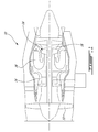
- FIG. 1 schematically shows a gas turbine engine incorporating a set of turbine blades
- FIG. 2 is an isometric view of an example of an improved turbine blade
- FIG. 3 is a cross-sectional view, viewed along the lines III-III in FIG. 4 , of the tip portion of the blade of FIG. 2 ;
- FIG. 4 is an end-on view of the turbine blade of FIG. 2 ;
- FIG. 5 is a cross-sectional view, similar to FIG. 3 , of the tip portion of another example of an improved turbine blade.
- FIG. 6 is a cross-sectional view, similar to FIG. 3 , of the tip portion of another example of an improved turbine blade.
- FIG. 1 illustrates an example of a gas turbine engine 10 of a type provided for use in subsonic flight, generally comprising in serial flow communication a fan 12 through which ambient air is propelled, a multistage compressor 14 for pressurizing the air, a combustor 16 in which the compressed air is mixed with fuel and ignited for generating an annular stream of hot combustion gases, and a turbine section 18 for extracting energy from the combustion gases.
- the turbine section 18 includes a plurality of blades 24 .
- FIG. 2 shows an example of an individual blade 24 as improved.
- the blade 24 has an airfoil 22 , which projects from a platform 23 to a free end or tip 20 .
- the airfoil 22 has opposite pressure and suction sidewalls 22 a , 22 b , as shown for example in FIG. 3 , extending chordwise between a leading edge and a trailing edge of the blade 24 .
- the tip 20 of the blade 24 includes two outwardly-and-upwardly-angled and chordwise-extending winglets 30 , 32 on the pressure side wall 22 a adjacent the blade tip.
- Each winglet 30 , 32 is laterally offset from the airfoil 22 , such that the tip of each winglet 30 , 32 extends away from a “plane” defined by the pressure sidewall 22 a of the airfoil 22 , as shown using the stippled line in FIG. 3 , to a terminal point outwardly therefrom.
- the tip of each winglet 30 , 32 need not extend by the same amount from the leading edge to the trailing edge.
- the lateral or horizontal extent of each winglet 30 , 32 may be selected depending on the blade pressure loading distribution, from leading edge to trailing edge, and thus tends to be an optimization for a particular blade design.
- the winglets 30 , 32 typically extend upwardly and outwardly at between 30 to 60 degrees from a vertical reference line for optimal performance, although any suitable angle may be employed.
- the winglets 30 , 32 need not be parallel but may typically be within about ⁇ 15 degrees in parallelism.
- the winglets 30 , 32 typically extend from a point on the pressure sidewall 22 a adjacent to the leading edge to a point on the pressure sidewall 22 a adjacent to the trailing edge. Winglet 30 and rib 40 cooperate to form a tip rail around the tip periphery, as shown in FIG. 4 .
- a row of inclined passageways 36 a optionally extend from a cooling circuit (in this example generically illustrated as 38 ) in the interior of the airfoil 22 to an outlet provided between the winglets 30 , 32 .
- the row may extend the entire length of the winglet(s), as shown in FIG. 4 , or may extend only along a portion thereof.
- the spacing between adjacent outlets in a row may be regular or not.
- the presence of outlets may be intermittent along the length of the row, as well. The designer will determine what is suitable for the design, in light of the teachings herein.
- a second row of inclined passageways 36 b may be provided below winglet 32 , extending thereto from internal pressurized cooling air circuit(s), in this example generically illustrated as 38 , as aforesaid, in the interior of the airfoil 22 .
- the spacing between adjacent outlets in a row may be regular or not.
- the presence of outlets of the passage ways 36 b may be intermittent along the length of the row, as well. The designer will determine what is suitable for the design, in light of the teachings herein.
- the position, length, chordwise extent, etc, of the second row 36 b need not be the same as the row 36 a.
- the passageways 36 a , 36 b typically are angled at about 30 to 60 degrees relative to a vertical reference line, but the angle may tend to be dependant somewhat on the positioning of the air circuit(s) 38 relative to the winglets 30 , 32 .
- the passageways 36 a , 36 b need not be parallel (amongst or within rows) but will usually be within about ⁇ 15 degrees in parallelism with each other and with the winglets 30 , 32 .
- the lower offset winglet 32 tends to isolate the upper offset winglet 30 and form a pocket where the tip leakage flow must negotiate a larger turn before passing over the upper winglet 30 . This may lead to a controlled separation region over the radially outer surface of the upper winglet 30 that displaces the air gap and may increase the tip leakage path resistance of the squealer tip 20 configuration (comprised of the upper offset winglet 30 and the rib 40 ) when compared to conventional pressure surface squealer tip designs, angled or not.
- passageways 36 a and/or 36 b pressurised air from the air circuit 38 is channeled to the outlets of the passageways 36 a and/or 36 b under the winglets 30 , 32 , which may increase the leakage resistance for the gas circulating over the squealer tip 20 from the pressure side to the section side.
- Air exiting the passageways 36 a and/or 36 b also provides cooling in the region of the squealer tip 20 .
- the presence of the flow from passageways 36 a and/or 36 b also tends to increase the resistance on the tip leakage flow.
- the winglets configuration tends to cause air flows injected below the winglet(s) to tend to remain in the region longer than would otherwise be the case, which may lead to improved blade tip cooling.
- the angle of adjacent passageways need not necessarily to be equal and the passageways are not necessarily straight or having the same supply location in the interior of the airfoil.
- the inner face 42 of the upper winglet 30 may also be substantially vertically extending.
- additional outlet passageways 36 c may be provided on the tip surface of the upper winglet 30 , if sufficient rib thickness is provided.
- the term “row” is used herein in broad sense and encompasses using staggered or other unaligned sets of passageways. Still other modifications will be apparent to those skilled in the art, in light of a review of this disclosure, and such modifications are intended to fall within the appended claims.
Landscapes
- Engineering & Computer Science (AREA)
- Mechanical Engineering (AREA)
- General Engineering & Computer Science (AREA)
- Turbine Rotor Nozzle Sealing (AREA)
Abstract
Description
Claims (10)
Priority Applications (2)
| Application Number | Priority Date | Filing Date | Title |
|---|---|---|---|
| US12/324,998 US8092178B2 (en) | 2008-11-28 | 2008-11-28 | Turbine blade for a gas turbine engine |
| CA2684779A CA2684779C (en) | 2008-11-28 | 2009-11-06 | Turbine blade with pressure side winglets |
Applications Claiming Priority (1)
| Application Number | Priority Date | Filing Date | Title |
|---|---|---|---|
| US12/324,998 US8092178B2 (en) | 2008-11-28 | 2008-11-28 | Turbine blade for a gas turbine engine |
Publications (2)
| Publication Number | Publication Date |
|---|---|
| US20100135813A1 US20100135813A1 (en) | 2010-06-03 |
| US8092178B2 true US8092178B2 (en) | 2012-01-10 |
Family
ID=42212024
Family Applications (1)
| Application Number | Title | Priority Date | Filing Date |
|---|---|---|---|
| US12/324,998 Active 2030-05-20 US8092178B2 (en) | 2008-11-28 | 2008-11-28 | Turbine blade for a gas turbine engine |
Country Status (2)
| Country | Link |
|---|---|
| US (1) | US8092178B2 (en) |
| CA (1) | CA2684779C (en) |
Cited By (23)
| Publication number | Priority date | Publication date | Assignee | Title |
|---|---|---|---|---|
| US20120189458A1 (en) * | 2011-01-20 | 2012-07-26 | Rolls-Royce Plc | Rotor blade |
| US8777567B2 (en) | 2010-09-22 | 2014-07-15 | Honeywell International Inc. | Turbine blades, turbine assemblies, and methods of manufacturing turbine blades |
| US20150361808A1 (en) * | 2014-06-17 | 2015-12-17 | Snecma | Turbomachine vane including an antivortex fin |
| US20160069189A1 (en) * | 2014-05-01 | 2016-03-10 | United Technologies Corporation | Splayed tip features for gas turbine engine airfoil |
| US9347320B2 (en) | 2013-10-23 | 2016-05-24 | General Electric Company | Turbine bucket profile yielding improved throat |
| US9376927B2 (en) | 2013-10-23 | 2016-06-28 | General Electric Company | Turbine nozzle having non-axisymmetric endwall contour (EWC) |
| US20160319673A1 (en) * | 2015-04-29 | 2016-11-03 | General Electric Company | Rotor blade having a flared tip |
| US9528379B2 (en) | 2013-10-23 | 2016-12-27 | General Electric Company | Turbine bucket having serpentine core |
| US9551226B2 (en) | 2013-10-23 | 2017-01-24 | General Electric Company | Turbine bucket with endwall contour and airfoil profile |
| US9638041B2 (en) | 2013-10-23 | 2017-05-02 | General Electric Company | Turbine bucket having non-axisymmetric base contour |
| US9670784B2 (en) | 2013-10-23 | 2017-06-06 | General Electric Company | Turbine bucket base having serpentine cooling passage with leading edge cooling |
| US9797258B2 (en) | 2013-10-23 | 2017-10-24 | General Electric Company | Turbine bucket including cooling passage with turn |
| US9816389B2 (en) | 2013-10-16 | 2017-11-14 | Honeywell International Inc. | Turbine rotor blades with tip portion parapet wall cavities |
| US9856739B2 (en) * | 2013-09-18 | 2018-01-02 | Honeywell International Inc. | Turbine blades with tip portions having converging cooling holes |
| US9879544B2 (en) | 2013-10-16 | 2018-01-30 | Honeywell International Inc. | Turbine rotor blades with improved tip portion cooling holes |
| US10041358B2 (en) | 2014-05-08 | 2018-08-07 | United Technologies Corporation | Gas turbine engine blade squealer pockets |
| US10053992B2 (en) | 2015-07-02 | 2018-08-21 | United Technologies Corporation | Gas turbine engine airfoil squealer pocket cooling hole configuration |
| US10253637B2 (en) | 2015-12-11 | 2019-04-09 | General Electric Company | Method and system for improving turbine blade performance |
| US10352180B2 (en) | 2013-10-23 | 2019-07-16 | General Electric Company | Gas turbine nozzle trailing edge fillet |
| US10787932B2 (en) | 2018-07-13 | 2020-09-29 | Honeywell International Inc. | Turbine blade with dust tolerant cooling system |
| US20220243597A1 (en) * | 2021-02-04 | 2022-08-04 | Doosan Heavy Industries & Construction Co., Ltd. | Airfoil with a squealer tip cooling system for a turbine blade, a turbine blade, a turbine blade assembly, a gas turbine and a manufacturing method |
| US11506062B2 (en) | 2020-09-25 | 2022-11-22 | Doosan Enerbility Co.. Ltd | Turbine blade, and turbine and gas turbine including the same |
| US11781433B1 (en) * | 2021-12-22 | 2023-10-10 | Rtx Corporation | Turbine blade tip cooling hole arrangement |
Families Citing this family (14)
| Publication number | Priority date | Publication date | Assignee | Title |
|---|---|---|---|---|
| EP2336492A1 (en) * | 2009-12-16 | 2011-06-22 | Siemens Aktiengesellschaft | Guide vane with a winglet for an energy converting machine and machine for converting energy comprising the guide vane |
| FR2982903B1 (en) * | 2011-11-17 | 2014-02-21 | Snecma | GAS TURBINE BLADE WITH INTRADOS SHIFTING OF HEAD SECTIONS AND COOLING CHANNELS |
| US9062554B2 (en) * | 2012-01-03 | 2015-06-23 | General Electric Company | Gas turbine nozzle with a flow groove |
| US8944774B2 (en) * | 2012-01-03 | 2015-02-03 | General Electric Company | Gas turbine nozzle with a flow fence |
| FR2986982B1 (en) * | 2012-02-22 | 2024-07-05 | Snecma | FOUNDRY CORE ASSEMBLY FOR THE MANUFACTURE OF A TURBOMACHINE BLADE, METHOD FOR MANUFACTURING A BLADE AND ASSOCIATED BLADE |
| US9273561B2 (en) * | 2012-08-03 | 2016-03-01 | General Electric Company | Cooling structures for turbine rotor blade tips |
| US10408066B2 (en) * | 2012-08-15 | 2019-09-10 | United Technologies Corporation | Suction side turbine blade tip cooling |
| EP2987956A1 (en) | 2014-08-18 | 2016-02-24 | Siemens Aktiengesellschaft | Compressor aerofoil |
| US10436038B2 (en) | 2015-12-07 | 2019-10-08 | General Electric Company | Turbine engine with an airfoil having a tip shelf outlet |
| US10227876B2 (en) * | 2015-12-07 | 2019-03-12 | General Electric Company | Fillet optimization for turbine airfoil |
| WO2018004766A1 (en) * | 2016-05-24 | 2018-01-04 | General Electric Company | Airfoil and blade for a turbine engine, and corresponding method of flowing a cooling fluid |
| US10830082B2 (en) * | 2017-05-10 | 2020-11-10 | General Electric Company | Systems including rotor blade tips and circumferentially grooved shrouds |
| KR102153066B1 (en) | 2018-10-01 | 2020-09-07 | 두산중공업 주식회사 | Turbine blade having cooling hole at winglet and gas turbine comprising the same |
| US12123319B2 (en) | 2020-12-30 | 2024-10-22 | Ge Infrastructure Technology Llc | Cooling circuit having a bypass conduit for a turbomachine component |
Citations (74)
| Publication number | Priority date | Publication date | Assignee | Title |
|---|---|---|---|---|
| US1828409A (en) | 1929-01-11 | 1931-10-20 | Westinghouse Electric & Mfg Co | Reaction blading |
| DE560589C (en) | 1932-10-04 | Franz Burghauser Dipl Ing | Device for reducing the blade gap loss of steam and gas turbines | |
| DE815971C (en) | 1949-12-22 | 1951-10-08 | Franz Burghauser | Steam or gas turbine blade with little radial clearance loss |
| GB946794A (en) | 1961-03-06 | 1964-01-15 | Colchester Woods | Improvements in and relating to axial flow fans or compressors |
| US4540339A (en) | 1984-06-01 | 1985-09-10 | The United States Of America As Represented By The Secretary Of The Air Force | One-piece HPTR blade squealer tip |
| US4874290A (en) | 1988-08-26 | 1989-10-17 | Solar Turbines Incorporated | Turbine blade top clearance control system |
| US4875831A (en) | 1987-11-19 | 1989-10-24 | Societe Nationale D'etude Et De Construction De Moteurs D'aviation "Snecma" | Compressor rotor blade having a tip with asymmetric lips |
| US4893987A (en) | 1987-12-08 | 1990-01-16 | General Electric Company | Diffusion-cooled blade tip cap |
| US4957411A (en) | 1987-05-13 | 1990-09-18 | Societe Nationale D'etude Et De Construction De Moteurs D'aviaton S.N.E.C.M.A. | Turbojet engine with fan rotor blades having tip clearance |
| US5183385A (en) | 1990-11-19 | 1993-02-02 | General Electric Company | Turbine blade squealer tip having air cooling holes contiguous with tip interior wall surface |
| US5261789A (en) | 1992-08-25 | 1993-11-16 | General Electric Company | Tip cooled blade |
| US5282721A (en) * | 1991-09-30 | 1994-02-01 | United Technologies Corporation | Passive clearance system for turbine blades |
| US5348446A (en) | 1993-04-28 | 1994-09-20 | General Electric Company | Bimetallic turbine airfoil |
| US5458461A (en) | 1994-12-12 | 1995-10-17 | General Electric Company | Film cooled slotted wall |
| US5476363A (en) | 1993-10-15 | 1995-12-19 | Charles E. Sohl | Method and apparatus for reducing stress on the tips of turbine or compressor blades |
| US5564902A (en) | 1994-04-21 | 1996-10-15 | Mitsubishi Jukogyo Kabushiki Kaisha | Gas turbine rotor blade tip cooling device |
| US5660523A (en) | 1992-02-03 | 1997-08-26 | General Electric Company | Turbine blade squealer tip peripheral end wall with cooling passage arrangement |
| US5733102A (en) | 1996-12-17 | 1998-03-31 | General Electric Company | Slot cooled blade tip |
| US5738491A (en) | 1997-01-03 | 1998-04-14 | General Electric Company | Conduction blade tip |
| US5822852A (en) | 1997-07-14 | 1998-10-20 | General Electric Company | Method for replacing blade tips of directionally solidified and single crystal turbine blades |
| US5997251A (en) | 1997-11-17 | 1999-12-07 | General Electric Company | Ribbed turbine blade tip |
| US6027306A (en) | 1997-06-23 | 2000-02-22 | General Electric Company | Turbine blade tip flow discouragers |
| US6039531A (en) | 1997-03-04 | 2000-03-21 | Mitsubishi Heavy Industries, Ltd. | Gas turbine blade |
| US6059530A (en) | 1998-12-21 | 2000-05-09 | General Electric Company | Twin rib turbine blade |
| US6086328A (en) | 1998-12-21 | 2000-07-11 | General Electric Company | Tapered tip turbine blade |
| US6135715A (en) | 1999-07-29 | 2000-10-24 | General Electric Company | Tip insulated airfoil |
| US6164914A (en) | 1999-08-23 | 2000-12-26 | General Electric Company | Cool tip blade |
| US6176678B1 (en) | 1998-11-06 | 2001-01-23 | General Electric Company | Apparatus and methods for turbine blade cooling |
| US6179556B1 (en) | 1999-06-01 | 2001-01-30 | General Electric Company | Turbine blade tip with offset squealer |
| US6183199B1 (en) | 1998-03-23 | 2001-02-06 | Abb Research Ltd. | Cooling-air bore |
| US6190129B1 (en) | 1998-12-21 | 2001-02-20 | General Electric Company | Tapered tip-rib turbine blade |
| US6224336B1 (en) | 1999-06-09 | 2001-05-01 | General Electric Company | Triple tip-rib airfoil |
| US6224337B1 (en) | 1999-09-17 | 2001-05-01 | General Electric Company | Thermal barrier coated squealer tip cavity |
| US6231307B1 (en) | 1999-06-01 | 2001-05-15 | General Electric Company | Impingement cooled airfoil tip |
| US6333121B1 (en) | 1992-10-13 | 2001-12-25 | General Electric Company | Low-sulfur article having a platinum-aluminide protective layer and its preparation |
| US6332272B1 (en) | 2000-01-07 | 2001-12-25 | Siemens Westinghouse Power Corporation | Method of repairing a turbine blade |
| US6382913B1 (en) | 2001-02-09 | 2002-05-07 | General Electric Company | Method and apparatus for reducing turbine blade tip region temperatures |
| US6422821B1 (en) | 2001-01-09 | 2002-07-23 | General Electric Company | Method and apparatus for reducing turbine blade tip temperatures |
| US20020136638A1 (en) | 2001-02-16 | 2002-09-26 | Siemens Westinghouse Power Corporation | Pre-segmented squealer tip for turbine blades |
| US20020141868A1 (en) | 2001-03-27 | 2002-10-03 | Ching-Pang Lee | Cooled thermal barrier coating on a turbine blade tip |
| US20020141869A1 (en) | 2001-03-27 | 2002-10-03 | Ching-Pang Lee | Turbine blade tip having thermal barrier coating-formed micro cooling channels |
| US6468040B1 (en) | 2000-07-24 | 2002-10-22 | General Electric Company | Environmentally resistant squealer tips and method for making |
| US20020187044A1 (en) | 2001-05-29 | 2002-12-12 | Ching-Pang Lee | Turbine airfoil and method for manufacture and repair thereof |
| US6494678B1 (en) * | 2001-05-31 | 2002-12-17 | General Electric Company | Film cooled blade tip |
| US20020197159A1 (en) | 2001-06-11 | 2002-12-26 | Norman Roeloffs | Turbine blade with rub tolerant cooling construction |
| US20020197160A1 (en) | 2001-06-20 | 2002-12-26 | George Liang | Airfoil tip squealer cooling construction |
| US20030021684A1 (en) | 2001-07-24 | 2003-01-30 | Downs James P. | Turbine blade tip cooling construction |
| US20030082054A1 (en) | 2001-11-01 | 2003-05-01 | Grylls Richard John | Oxidation resistant and/or abrasion resistant squealer tip and method for casting same |
| US20030118444A1 (en) | 2001-12-20 | 2003-06-26 | Ching-Pang Lee | Foil formed structure for turbine airfoil tip |
| US6672829B1 (en) | 2002-07-16 | 2004-01-06 | General Electric Company | Turbine blade having angled squealer tip |
| US20040096328A1 (en) | 2002-11-20 | 2004-05-20 | Mitsubishi Heavy Industries Ltd. | Turbine blade and gas turbine |
| US20040109754A1 (en) | 2002-12-06 | 2004-06-10 | Townes Roderick M. | Blade cooling |
| US20040126236A1 (en) | 2002-12-30 | 2004-07-01 | Ching-Pang Lee | Compound tip notched blade |
| US20040197190A1 (en) | 2003-04-07 | 2004-10-07 | Stec Philip Francis | Turbine blade with recessed squealer tip and shelf |
| US20050095129A1 (en) | 2003-10-31 | 2005-05-05 | Benjamin Edward D. | Methods and apparatus for assembling gas turbine engine rotor assemblies |
| US20050244270A1 (en) | 2004-04-30 | 2005-11-03 | Siemens Westinghouse Power Corporation | Cooling system for a tip of a turbine blade |
| US20050281671A1 (en) | 2004-06-17 | 2005-12-22 | Siemens Westinghouse Power Corporation | Gas turbine airfoil trailing edge corner |
| US20060051209A1 (en) | 2004-09-09 | 2006-03-09 | Ching-Pang Lee | Fluted tip turbine blade |
| US20060062671A1 (en) | 2004-07-26 | 2006-03-23 | Ching-Pang Lee | Common tip chamber blade |
| US20060067821A1 (en) | 2004-09-28 | 2006-03-30 | Wadia Aspi R | Methods and apparatus for aerodynamically self-enhancing rotor blades |
| US20060088420A1 (en) | 2004-10-21 | 2006-04-27 | General Electric Company | Turbine blade tip squealer and rebuild method |
| US20060174482A1 (en) | 2005-02-09 | 2006-08-10 | General Electric Company | Gas turbine blade having a monocrystalline airfoil with a repair squealer tip, and repair method |
| US20060257257A1 (en) | 2005-05-13 | 2006-11-16 | Snecma | Hollow rotor blade for the turbine of a gas turbine engine, the blade being fitted with a "bathtub" |
| US20070059173A1 (en) | 2005-09-09 | 2007-03-15 | General Electric Company | Turbine airfoil curved squealer tip with tip shelf |
| US20070059182A1 (en) * | 2005-09-09 | 2007-03-15 | General Electric Company | Turbine airfoil with curved squealer tip |
| EP1764477A1 (en) | 2005-09-14 | 2007-03-21 | General Electric Company | Fluted tip turbine blade |
| US20070128033A1 (en) | 2005-12-05 | 2007-06-07 | General Electric Company | Blunt tip turbine blade |
| US20070237637A1 (en) | 2005-08-25 | 2007-10-11 | General Electric Company | Skewed tip hole turbine blade |
| US20070248750A1 (en) | 2005-03-17 | 2007-10-25 | Siemens Power Generation, Inc. | Cold spray method for producing gas turbine blade tip |
| US20070258815A1 (en) | 2006-05-02 | 2007-11-08 | Siemens Power Generation, Inc. | Turbine blade with wavy squealer tip rail |
| US20080118367A1 (en) | 2006-11-21 | 2008-05-22 | Siemens Power Generation, Inc. | Cooling of turbine blade suction tip rail |
| US20080226460A1 (en) | 2006-11-24 | 2008-09-18 | Ihi Corporation | Compressor rotor |
| EP1721698B1 (en) | 2005-05-09 | 2008-11-26 | Snecma Services | Method of manufacturing a hollow blade comprising a squealer tip and method of repairing such a blade |
| US20090081024A1 (en) * | 2005-12-03 | 2009-03-26 | Rolls-Royce Plc | Turbine blade |
-
2008
- 2008-11-28 US US12/324,998 patent/US8092178B2/en active Active
-
2009
- 2009-11-06 CA CA2684779A patent/CA2684779C/en not_active Expired - Fee Related
Patent Citations (81)
| Publication number | Priority date | Publication date | Assignee | Title |
|---|---|---|---|---|
| DE560589C (en) | 1932-10-04 | Franz Burghauser Dipl Ing | Device for reducing the blade gap loss of steam and gas turbines | |
| US1828409A (en) | 1929-01-11 | 1931-10-20 | Westinghouse Electric & Mfg Co | Reaction blading |
| DE815971C (en) | 1949-12-22 | 1951-10-08 | Franz Burghauser | Steam or gas turbine blade with little radial clearance loss |
| GB946794A (en) | 1961-03-06 | 1964-01-15 | Colchester Woods | Improvements in and relating to axial flow fans or compressors |
| US4540339A (en) | 1984-06-01 | 1985-09-10 | The United States Of America As Represented By The Secretary Of The Air Force | One-piece HPTR blade squealer tip |
| US4957411A (en) | 1987-05-13 | 1990-09-18 | Societe Nationale D'etude Et De Construction De Moteurs D'aviaton S.N.E.C.M.A. | Turbojet engine with fan rotor blades having tip clearance |
| US4875831A (en) | 1987-11-19 | 1989-10-24 | Societe Nationale D'etude Et De Construction De Moteurs D'aviation "Snecma" | Compressor rotor blade having a tip with asymmetric lips |
| US4893987A (en) | 1987-12-08 | 1990-01-16 | General Electric Company | Diffusion-cooled blade tip cap |
| US4874290A (en) | 1988-08-26 | 1989-10-17 | Solar Turbines Incorporated | Turbine blade top clearance control system |
| US5183385A (en) | 1990-11-19 | 1993-02-02 | General Electric Company | Turbine blade squealer tip having air cooling holes contiguous with tip interior wall surface |
| US5282721A (en) * | 1991-09-30 | 1994-02-01 | United Technologies Corporation | Passive clearance system for turbine blades |
| US5660523A (en) | 1992-02-03 | 1997-08-26 | General Electric Company | Turbine blade squealer tip peripheral end wall with cooling passage arrangement |
| US5261789A (en) | 1992-08-25 | 1993-11-16 | General Electric Company | Tip cooled blade |
| US6333121B1 (en) | 1992-10-13 | 2001-12-25 | General Electric Company | Low-sulfur article having a platinum-aluminide protective layer and its preparation |
| US5348446A (en) | 1993-04-28 | 1994-09-20 | General Electric Company | Bimetallic turbine airfoil |
| US5476363A (en) | 1993-10-15 | 1995-12-19 | Charles E. Sohl | Method and apparatus for reducing stress on the tips of turbine or compressor blades |
| US5564902A (en) | 1994-04-21 | 1996-10-15 | Mitsubishi Jukogyo Kabushiki Kaisha | Gas turbine rotor blade tip cooling device |
| US5458461A (en) | 1994-12-12 | 1995-10-17 | General Electric Company | Film cooled slotted wall |
| US5733102A (en) | 1996-12-17 | 1998-03-31 | General Electric Company | Slot cooled blade tip |
| US5738491A (en) | 1997-01-03 | 1998-04-14 | General Electric Company | Conduction blade tip |
| US6039531A (en) | 1997-03-04 | 2000-03-21 | Mitsubishi Heavy Industries, Ltd. | Gas turbine blade |
| US6027306A (en) | 1997-06-23 | 2000-02-22 | General Electric Company | Turbine blade tip flow discouragers |
| US5822852A (en) | 1997-07-14 | 1998-10-20 | General Electric Company | Method for replacing blade tips of directionally solidified and single crystal turbine blades |
| US5997251A (en) | 1997-11-17 | 1999-12-07 | General Electric Company | Ribbed turbine blade tip |
| US6183199B1 (en) | 1998-03-23 | 2001-02-06 | Abb Research Ltd. | Cooling-air bore |
| US6176678B1 (en) | 1998-11-06 | 2001-01-23 | General Electric Company | Apparatus and methods for turbine blade cooling |
| US6059530A (en) | 1998-12-21 | 2000-05-09 | General Electric Company | Twin rib turbine blade |
| US6190129B1 (en) | 1998-12-21 | 2001-02-20 | General Electric Company | Tapered tip-rib turbine blade |
| US6086328A (en) | 1998-12-21 | 2000-07-11 | General Electric Company | Tapered tip turbine blade |
| US6179556B1 (en) | 1999-06-01 | 2001-01-30 | General Electric Company | Turbine blade tip with offset squealer |
| US6231307B1 (en) | 1999-06-01 | 2001-05-15 | General Electric Company | Impingement cooled airfoil tip |
| US6224336B1 (en) | 1999-06-09 | 2001-05-01 | General Electric Company | Triple tip-rib airfoil |
| US6135715A (en) | 1999-07-29 | 2000-10-24 | General Electric Company | Tip insulated airfoil |
| US6164914A (en) | 1999-08-23 | 2000-12-26 | General Electric Company | Cool tip blade |
| US6224337B1 (en) | 1999-09-17 | 2001-05-01 | General Electric Company | Thermal barrier coated squealer tip cavity |
| US6332272B1 (en) | 2000-01-07 | 2001-12-25 | Siemens Westinghouse Power Corporation | Method of repairing a turbine blade |
| US6468040B1 (en) | 2000-07-24 | 2002-10-22 | General Electric Company | Environmentally resistant squealer tips and method for making |
| US6422821B1 (en) | 2001-01-09 | 2002-07-23 | General Electric Company | Method and apparatus for reducing turbine blade tip temperatures |
| US6382913B1 (en) | 2001-02-09 | 2002-05-07 | General Electric Company | Method and apparatus for reducing turbine blade tip region temperatures |
| US20020136638A1 (en) | 2001-02-16 | 2002-09-26 | Siemens Westinghouse Power Corporation | Pre-segmented squealer tip for turbine blades |
| US20020141868A1 (en) | 2001-03-27 | 2002-10-03 | Ching-Pang Lee | Cooled thermal barrier coating on a turbine blade tip |
| US20020141869A1 (en) | 2001-03-27 | 2002-10-03 | Ching-Pang Lee | Turbine blade tip having thermal barrier coating-formed micro cooling channels |
| US20020187044A1 (en) | 2001-05-29 | 2002-12-12 | Ching-Pang Lee | Turbine airfoil and method for manufacture and repair thereof |
| US6494678B1 (en) * | 2001-05-31 | 2002-12-17 | General Electric Company | Film cooled blade tip |
| US20020197159A1 (en) | 2001-06-11 | 2002-12-26 | Norman Roeloffs | Turbine blade with rub tolerant cooling construction |
| US20020197160A1 (en) | 2001-06-20 | 2002-12-26 | George Liang | Airfoil tip squealer cooling construction |
| US20030021684A1 (en) | 2001-07-24 | 2003-01-30 | Downs James P. | Turbine blade tip cooling construction |
| US20030082054A1 (en) | 2001-11-01 | 2003-05-01 | Grylls Richard John | Oxidation resistant and/or abrasion resistant squealer tip and method for casting same |
| US20030118444A1 (en) | 2001-12-20 | 2003-06-26 | Ching-Pang Lee | Foil formed structure for turbine airfoil tip |
| US6672829B1 (en) | 2002-07-16 | 2004-01-06 | General Electric Company | Turbine blade having angled squealer tip |
| US20040096328A1 (en) | 2002-11-20 | 2004-05-20 | Mitsubishi Heavy Industries Ltd. | Turbine blade and gas turbine |
| US20040109754A1 (en) | 2002-12-06 | 2004-06-10 | Townes Roderick M. | Blade cooling |
| US20040126236A1 (en) | 2002-12-30 | 2004-07-01 | Ching-Pang Lee | Compound tip notched blade |
| US6790005B2 (en) | 2002-12-30 | 2004-09-14 | General Electric Company | Compound tip notched blade |
| US20040197190A1 (en) | 2003-04-07 | 2004-10-07 | Stec Philip Francis | Turbine blade with recessed squealer tip and shelf |
| US6991430B2 (en) | 2003-04-07 | 2006-01-31 | General Electric Company | Turbine blade with recessed squealer tip and shelf |
| US20050095129A1 (en) | 2003-10-31 | 2005-05-05 | Benjamin Edward D. | Methods and apparatus for assembling gas turbine engine rotor assemblies |
| US20050244270A1 (en) | 2004-04-30 | 2005-11-03 | Siemens Westinghouse Power Corporation | Cooling system for a tip of a turbine blade |
| US7029235B2 (en) | 2004-04-30 | 2006-04-18 | Siemens Westinghouse Power Corporation | Cooling system for a tip of a turbine blade |
| US20050281671A1 (en) | 2004-06-17 | 2005-12-22 | Siemens Westinghouse Power Corporation | Gas turbine airfoil trailing edge corner |
| US20060062671A1 (en) | 2004-07-26 | 2006-03-23 | Ching-Pang Lee | Common tip chamber blade |
| US20060051209A1 (en) | 2004-09-09 | 2006-03-09 | Ching-Pang Lee | Fluted tip turbine blade |
| US7118342B2 (en) | 2004-09-09 | 2006-10-10 | General Electric Company | Fluted tip turbine blade |
| US20060067821A1 (en) | 2004-09-28 | 2006-03-30 | Wadia Aspi R | Methods and apparatus for aerodynamically self-enhancing rotor blades |
| US20060088420A1 (en) | 2004-10-21 | 2006-04-27 | General Electric Company | Turbine blade tip squealer and rebuild method |
| US20060174482A1 (en) | 2005-02-09 | 2006-08-10 | General Electric Company | Gas turbine blade having a monocrystalline airfoil with a repair squealer tip, and repair method |
| US20070248750A1 (en) | 2005-03-17 | 2007-10-25 | Siemens Power Generation, Inc. | Cold spray method for producing gas turbine blade tip |
| EP1721698B1 (en) | 2005-05-09 | 2008-11-26 | Snecma Services | Method of manufacturing a hollow blade comprising a squealer tip and method of repairing such a blade |
| US20060257257A1 (en) | 2005-05-13 | 2006-11-16 | Snecma | Hollow rotor blade for the turbine of a gas turbine engine, the blade being fitted with a "bathtub" |
| US7351035B2 (en) * | 2005-05-13 | 2008-04-01 | Snecma | Hollow rotor blade for the turbine of a gas turbine engine, the blade being fitted with a “bathtub” |
| US20070237637A1 (en) | 2005-08-25 | 2007-10-11 | General Electric Company | Skewed tip hole turbine blade |
| US7281894B2 (en) * | 2005-09-09 | 2007-10-16 | General Electric Company | Turbine airfoil curved squealer tip with tip shelf |
| US20070059182A1 (en) * | 2005-09-09 | 2007-03-15 | General Electric Company | Turbine airfoil with curved squealer tip |
| US20070059173A1 (en) | 2005-09-09 | 2007-03-15 | General Electric Company | Turbine airfoil curved squealer tip with tip shelf |
| EP1764477A1 (en) | 2005-09-14 | 2007-03-21 | General Electric Company | Fluted tip turbine blade |
| EP1764477B1 (en) | 2005-09-14 | 2008-07-02 | General Electric Company | Fluted tip turbine blade |
| US20090081024A1 (en) * | 2005-12-03 | 2009-03-26 | Rolls-Royce Plc | Turbine blade |
| US20070128033A1 (en) | 2005-12-05 | 2007-06-07 | General Electric Company | Blunt tip turbine blade |
| US20070258815A1 (en) | 2006-05-02 | 2007-11-08 | Siemens Power Generation, Inc. | Turbine blade with wavy squealer tip rail |
| US20080118367A1 (en) | 2006-11-21 | 2008-05-22 | Siemens Power Generation, Inc. | Cooling of turbine blade suction tip rail |
| US20080226460A1 (en) | 2006-11-24 | 2008-09-18 | Ihi Corporation | Compressor rotor |
Cited By (31)
| Publication number | Priority date | Publication date | Assignee | Title |
|---|---|---|---|---|
| US8777567B2 (en) | 2010-09-22 | 2014-07-15 | Honeywell International Inc. | Turbine blades, turbine assemblies, and methods of manufacturing turbine blades |
| US8777572B2 (en) * | 2011-01-20 | 2014-07-15 | Rolls-Royce Plc | Rotor blade |
| US20120189458A1 (en) * | 2011-01-20 | 2012-07-26 | Rolls-Royce Plc | Rotor blade |
| US9856739B2 (en) * | 2013-09-18 | 2018-01-02 | Honeywell International Inc. | Turbine blades with tip portions having converging cooling holes |
| US9816389B2 (en) | 2013-10-16 | 2017-11-14 | Honeywell International Inc. | Turbine rotor blades with tip portion parapet wall cavities |
| US9879544B2 (en) | 2013-10-16 | 2018-01-30 | Honeywell International Inc. | Turbine rotor blades with improved tip portion cooling holes |
| US9376927B2 (en) | 2013-10-23 | 2016-06-28 | General Electric Company | Turbine nozzle having non-axisymmetric endwall contour (EWC) |
| US9347320B2 (en) | 2013-10-23 | 2016-05-24 | General Electric Company | Turbine bucket profile yielding improved throat |
| US9528379B2 (en) | 2013-10-23 | 2016-12-27 | General Electric Company | Turbine bucket having serpentine core |
| US9551226B2 (en) | 2013-10-23 | 2017-01-24 | General Electric Company | Turbine bucket with endwall contour and airfoil profile |
| US9638041B2 (en) | 2013-10-23 | 2017-05-02 | General Electric Company | Turbine bucket having non-axisymmetric base contour |
| US9670784B2 (en) | 2013-10-23 | 2017-06-06 | General Electric Company | Turbine bucket base having serpentine cooling passage with leading edge cooling |
| US9797258B2 (en) | 2013-10-23 | 2017-10-24 | General Electric Company | Turbine bucket including cooling passage with turn |
| US10352180B2 (en) | 2013-10-23 | 2019-07-16 | General Electric Company | Gas turbine nozzle trailing edge fillet |
| US10329916B2 (en) * | 2014-05-01 | 2019-06-25 | United Technologies Corporation | Splayed tip features for gas turbine engine airfoil |
| US11268387B2 (en) * | 2014-05-01 | 2022-03-08 | Raytheon Technologies Corporation | Splayed tip features for gas turbine engine airfoil |
| US20160069189A1 (en) * | 2014-05-01 | 2016-03-10 | United Technologies Corporation | Splayed tip features for gas turbine engine airfoil |
| US10041358B2 (en) | 2014-05-08 | 2018-08-07 | United Technologies Corporation | Gas turbine engine blade squealer pockets |
| US10260361B2 (en) * | 2014-06-17 | 2019-04-16 | Safran Aircraft Engines | Turbomachine vane including an antivortex fin |
| US20150361808A1 (en) * | 2014-06-17 | 2015-12-17 | Snecma | Turbomachine vane including an antivortex fin |
| US10107108B2 (en) * | 2015-04-29 | 2018-10-23 | General Electric Company | Rotor blade having a flared tip |
| US20160319673A1 (en) * | 2015-04-29 | 2016-11-03 | General Electric Company | Rotor blade having a flared tip |
| US10053992B2 (en) | 2015-07-02 | 2018-08-21 | United Technologies Corporation | Gas turbine engine airfoil squealer pocket cooling hole configuration |
| US10253637B2 (en) | 2015-12-11 | 2019-04-09 | General Electric Company | Method and system for improving turbine blade performance |
| US10934858B2 (en) | 2015-12-11 | 2021-03-02 | General Electric Company | Method and system for improving turbine blade performance |
| US10787932B2 (en) | 2018-07-13 | 2020-09-29 | Honeywell International Inc. | Turbine blade with dust tolerant cooling system |
| US11333042B2 (en) | 2018-07-13 | 2022-05-17 | Honeywell International Inc. | Turbine blade with dust tolerant cooling system |
| US11506062B2 (en) | 2020-09-25 | 2022-11-22 | Doosan Enerbility Co.. Ltd | Turbine blade, and turbine and gas turbine including the same |
| US20220243597A1 (en) * | 2021-02-04 | 2022-08-04 | Doosan Heavy Industries & Construction Co., Ltd. | Airfoil with a squealer tip cooling system for a turbine blade, a turbine blade, a turbine blade assembly, a gas turbine and a manufacturing method |
| US11572792B2 (en) * | 2021-02-04 | 2023-02-07 | Doosan Enerbility Co., Ltd. | Airfoil with a squealer tip cooling system for a turbine blade, a turbine blade, a turbine blade assembly, a gas turbine and a manufacturing method |
| US11781433B1 (en) * | 2021-12-22 | 2023-10-10 | Rtx Corporation | Turbine blade tip cooling hole arrangement |
Also Published As
| Publication number | Publication date |
|---|---|
| CA2684779A1 (en) | 2010-05-28 |
| US20100135813A1 (en) | 2010-06-03 |
| CA2684779C (en) | 2013-04-16 |
Similar Documents
| Publication | Publication Date | Title |
|---|---|---|
| US8092178B2 (en) | Turbine blade for a gas turbine engine | |
| US20240159151A1 (en) | Airfoil for a turbine engine | |
| US20100135822A1 (en) | Turbine blade for a gas turbine engine | |
| US10934858B2 (en) | Method and system for improving turbine blade performance | |
| US10436038B2 (en) | Turbine engine with an airfoil having a tip shelf outlet | |
| US9103217B2 (en) | Turbine blade tip with tip shelf diffuser holes | |
| US10415392B2 (en) | End wall configuration for gas turbine engine | |
| US8105037B2 (en) | Endwall with leading-edge hump | |
| US8961135B2 (en) | Mateface gap configuration for gas turbine engine | |
| US9045988B2 (en) | Turbine bucket with squealer tip | |
| US12421853B2 (en) | Turbine engine with reduced cross flow airfoils | |
| US20130302176A1 (en) | Turbine airfoil trailing edge cooling slot | |
| US10830057B2 (en) | Airfoil with tip rail cooling | |
| US7059825B2 (en) | Cooled rotor blade | |
| US10830060B2 (en) | Engine component with flow enhancer | |
| US20220106884A1 (en) | Turbine engine component with deflector | |
| US20180073370A1 (en) | Turbine blade cooling | |
| US10450874B2 (en) | Airfoil for a gas turbine engine | |
| US11549377B2 (en) | Airfoil with cooling hole | |
| US8790084B2 (en) | Airfoil and method of fabricating the same | |
| US10329922B2 (en) | Gas turbine engine airfoil | |
| US20200240276A1 (en) | Turbine blade and corresponding method of servicing |
Legal Events
| Date | Code | Title | Description |
|---|---|---|---|
| AS | Assignment |
Owner name: PRATT & WHITNEY CANADA CORP.,CANADA Free format text: ASSIGNMENT OF ASSIGNORS INTEREST;ASSIGNORS:MARINI, REMO;GIRGIS, SAMI;REEL/FRAME:021902/0398 Effective date: 20081127 Owner name: PRATT & WHITNEY CANADA CORP., CANADA Free format text: ASSIGNMENT OF ASSIGNORS INTEREST;ASSIGNORS:MARINI, REMO;GIRGIS, SAMI;REEL/FRAME:021902/0398 Effective date: 20081127 |
|
| STCF | Information on status: patent grant |
Free format text: PATENTED CASE |
|
| FPAY | Fee payment |
Year of fee payment: 4 |
|
| MAFP | Maintenance fee payment |
Free format text: PAYMENT OF MAINTENANCE FEE, 8TH YEAR, LARGE ENTITY (ORIGINAL EVENT CODE: M1552); ENTITY STATUS OF PATENT OWNER: LARGE ENTITY Year of fee payment: 8 |
|
| MAFP | Maintenance fee payment |
Free format text: PAYMENT OF MAINTENANCE FEE, 12TH YEAR, LARGE ENTITY (ORIGINAL EVENT CODE: M1553); ENTITY STATUS OF PATENT OWNER: LARGE ENTITY Year of fee payment: 12 |