US809208A - Windmill. - Google Patents
Windmill. Download PDFInfo
- Publication number
- US809208A US809208A US25946205A US1905259462A US809208A US 809208 A US809208 A US 809208A US 25946205 A US25946205 A US 25946205A US 1905259462 A US1905259462 A US 1905259462A US 809208 A US809208 A US 809208A
- Authority
- US
- United States
- Prior art keywords
- crank
- primary
- auxiliary
- pawl
- support
- Prior art date
- Legal status (The legal status is an assumption and is not a legal conclusion. Google has not performed a legal analysis and makes no representation as to the accuracy of the status listed.)
- Expired - Lifetime
Links
- 230000007246 mechanism Effects 0.000 description 27
- 238000010276 construction Methods 0.000 description 4
- 239000007788 liquid Substances 0.000 description 4
- 230000001276 controlling effect Effects 0.000 description 2
- 230000001105 regulatory effect Effects 0.000 description 2
- 230000000717 retained effect Effects 0.000 description 2
- 230000003534 oscillatory effect Effects 0.000 description 1
- 230000000630 rising effect Effects 0.000 description 1
Images
Classifications
-
- F—MECHANICAL ENGINEERING; LIGHTING; HEATING; WEAPONS; BLASTING
- F04—POSITIVE - DISPLACEMENT MACHINES FOR LIQUIDS; PUMPS FOR LIQUIDS OR ELASTIC FLUIDS
- F04B—POSITIVE-DISPLACEMENT MACHINES FOR LIQUIDS; PUMPS
- F04B49/00—Control, e.g. of pump delivery, or pump pressure of, or safety measures for, machines, pumps, or pumping installations, not otherwise provided for, or of interest apart from, groups F04B1/00 - F04B47/00
- F04B49/02—Stopping, starting, unloading or idling control
- F04B49/025—Stopping, starting, unloading or idling control by means of floats
-
- F—MECHANICAL ENGINEERING; LIGHTING; HEATING; WEAPONS; BLASTING
- F03—MACHINES OR ENGINES FOR LIQUIDS; WIND, SPRING, OR WEIGHT MOTORS; PRODUCING MECHANICAL POWER OR A REACTIVE PROPULSIVE THRUST, NOT OTHERWISE PROVIDED FOR
- F03D—WIND MOTORS
- F03D9/00—Adaptations of wind motors for special use; Combinations of wind motors with apparatus driven thereby; Wind motors specially adapted for installation in particular locations
- F03D9/20—Wind motors characterised by the driven apparatus
- F03D9/28—Wind motors characterised by the driven apparatus the apparatus being a pump or a compressor
-
- Y—GENERAL TAGGING OF NEW TECHNOLOGICAL DEVELOPMENTS; GENERAL TAGGING OF CROSS-SECTIONAL TECHNOLOGIES SPANNING OVER SEVERAL SECTIONS OF THE IPC; TECHNICAL SUBJECTS COVERED BY FORMER USPC CROSS-REFERENCE ART COLLECTIONS [XRACs] AND DIGESTS
- Y02—TECHNOLOGIES OR APPLICATIONS FOR MITIGATION OR ADAPTATION AGAINST CLIMATE CHANGE
- Y02E—REDUCTION OF GREENHOUSE GAS [GHG] EMISSIONS, RELATED TO ENERGY GENERATION, TRANSMISSION OR DISTRIBUTION
- Y02E10/00—Energy generation through renewable energy sources
- Y02E10/70—Wind energy
- Y02E10/72—Wind turbines with rotation axis in wind direction
Definitions
- Patented J an. 2, 1906.
- This invention relates to improvements in windmill-regulating mechanisms.
- One of the objects of the invention is to improve the structure of a regulating mechanism which cooperates with a windmill for retaining liquids in a tank or reservoir at a predetermined level.
- Another object of the invention is the provision of means which is actuated by a float for moving the vane of a windmill from an operative to an inoperative position.
- a still further object of the invention is the construction of a regulator which comprises a minimum number of parts and which is I simple and inexpensive in construction.
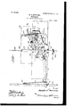
- Figure 1 is a view in side elevation of a mechanism constructed in accordance with the present invention.
- Fig. 2 is a top plan view of the mechanism which is shown in Fig. 1 with the cover removed.
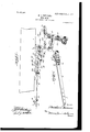
- Fig. 8 is an end view of the mechanism.
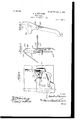
- Fig. 4 is a fragmentary view of the mechanism shown in a locked or inoperative position.
- Fig. 5 is a perspective view of the oscillatory bifurcated lever.
- Fig.- 6 is a perspective view of the primary pawl.
- Fig. 7 is a view in side elevation of the auxiliary crank member.
- 1 indicates a support, preferably a beam of the framework of a windmill carrying the regulating mechanism.
- a plate 2 is secured to the support 1 by any suitable means-as, for instance, rivets or bolts 3.
- a bifurcated lever 4 is mounted upon an extension 5a, projecting from the plate 2.
- the lever 4 is provided at one end with integral parallel extensions 5 and 6, and formed in its opposite end are apertures 7 Hollow extensions 8 8 are formed integral upon the lever 4.
- the l shaft 5aL of plate 2 is adapted to be positioned within the apertured portion of extensions 8. After the lever 4 has been positioned upon shaft 5a said lever is retained thereon by any suitable securing means, as member 9.
- the lever 4 is connected to pump-rod 10 through the medium of an angular member 11.
- the connecting member 11 is provided with a right-angled extension 12, formed upon each end.
- the lower extension 12 is positioned within one of the apertured portions 7 of the lover 4.
- a fastening member 13 is secured upon the lower extension 12 of the connecting member 1 1 for retaining said member in an adjusted position upon the lever.
- a washer 14 Interposed between lever 4 and the fastening member 13 is a washer 14.
- I provide a bracket 15, secured to the pump-rod 10, for fastening the upper angular end 12 of the connecting-rod 11 in an operative position with said pump-rod 10.
- the bracket 15 is provided with an eye or aperture through which the upper angular end of the connecting rod 11 extends.
- a removable fastening member 16 Positioned upon the outer end of said upper portion 12 of the rod 11 is a removable fastening member 16. The adjustability of the connecting-rod 10 is desirable for governing the movement of the lever 4.
- the pump-rod 10 will necessitate shorter movement of the lever 4, and this may be accomplished by adjusting the lowerend of the connecting-rod in the apertures of the lever 4.
- the extension 5 of the lever 4 is provided with a laterally-extendingshaft 16
- the extension 6 is also provided with a shaft 17.
- the shafts 16 and 17 are formed for providing a suitable bearing upon which the primary pawl 18 is carried.
- the primary pawl 18 comprises parallel sides 19 and 20, integrally connected bymeans of an upper angular extension 2,1.
- the extension 21 is provided with a 14tioth 22 and with an elongated slot 23. Formed integral upon the sides or parallel extensions 19 and 2O is a slotted weighted extension 24.
- the ratchet-bar 25 is secured in a vertical position upon the plate 2 by means of guides 26.
- Each of the guides 26 is provided with a IOO fiat back portion 27 and with a beveled front portion 28. It willbe noted that the ratchetbar 25 will not be prevented from moving downwardly by reason of the fact that the teeth will ride over the front face of the guides 26. If i did not provide the beveled surface 28 upon each of the guides, when the bar 25 was moved upwardly the teeth would engage the unbeveled edge of the guide and prevent said movement.
- An aperture 29 is formed in the upper end of the ratchet-bar 25.
- Connecting means, as wire 30, is secured in the apertured portions 29 of bar 25 and to the vane of the windmill.
- the float When the liquid in the tank or reservoir has fallen below a predetermined level, the float, which is secured to the wire or cable 31, will operate the guiding ⁇ means hereinafter described for moving the primary pawl 18, as well as the auxiliary pawl 32, from engagement with the ratchet-bar 25, permitting said bar to move upward, and thereby allowing the pump to be actuated.
- the movable slotted member 33 upon the ratchet-bar 25.
- the member 33 is provided with a locking-b olt 34, By adjusting the member 33 toward the upper end of the ratchet-bar 25 said bar is limited in its upper movement, and of course the vane connected to the wire 30 will not be permitted to swing fully into the wind if it is necessary for the member 33 to be secured to the extreme lowest portion of the bar 25, when the vane is permitted to be placed fully into the wind under normal conditions.
- the removable auxiliary pawl 32 is provided with an angular end 36.
- the guiding means for the primary and auxiliary pawls comprises a longitudinal movable bar 37, which is mounted within guides 38 and 39.
- the bar 37 constitutes a guide for the primary pawl 18.
- the body portion of the bar 37 which lies in a horizoni tal plane, is provided with a right-angled extension 40, which is positioned within the elongated slot 23 of pawl 18. It will be obvious that the pawl 18 may move upon the extension 40 of the bar 37.
- Positioned upon the shaft or cylindrical extension 41 of plate 2 are primary and auxiliary cranks 42 and 43, respectively.
- the crank 42 is secured upon the outer portion of the extension 41 next to the fastening member 44.
- the auxiliary crank 43 is interposed between the plate 2 and the primary crank 42.
- the primary crank comprises two portions bent at substantially right angles to each other, one of which is provided with apertures 45, adapted to receive the wire 31, which is connected to the oat in the tank.
- the other portion of the primary crank is formed with a weighted end 46.
- the weighted end 46 is provided with'an apertured extension 47.
- the apertured extension 47 of the weighted portion of the primary crank is employed for furnishing means whereby additional weights may be attached to the primary crank if desired.
- the auxiliary crank, Fig. 7, is provided with a curved lower end 48, which is adapted to engage the curved or angular end 36 of the pawl 32 when the mechanism is operated to cause the vane to swing into the wind.
- the auxiliary crank is provided with a longitudinal aperture 52 and a transverse aperture 53. Within the longitudinal aperture 52 is positioned a guide-bar 37. The guide-bar 37 is retained in a fixed position with the auxiliary crank 43 by transverse fastening means 54. The transverse fastening means 54 is positioned within the aperture 53.
- crank 43 When the crank 43 moves forward, it forces the horizontally-movable member 37 toward the ratchet-bar 25, and consequently swings the primary pawl 18 upon the lever, permitting said pawl when member 37 is moved to its farthest position toward the ratchet-bar 25 to engage the ratchet-bar 25.
- a cam 55 Upon the inner face of the primary crank 42 there is formed a cam 55, constituting a stop. This cam or stop 55 is of sufficient length to engage the extension 51 of the auxiliary crank 43 when said primary crank is swung upon 41.
- the plate 2 is provided with a horizontal extension 56, upon which is mounted a dog 57.
- the dog 57 is employed for locking the mechanism in an inoperative position, Fig. 4, while the vane is in the wind.
- the dog 57 falls into its seated position, Fig. 4, at
- the dog 57 is curved at ⁇ its outer end, permitting the cam to -ride freely over its under surface while moving inwardly until it reaches the portion 58, when said cam will beginto raise the dog 57 until the same has been removed from its seated position, Fig. 4, and thereby permitting the auxiliary crank 43 and guide member 37 to move for positioning the primary and auxiliary pawls 18 and 32, respectively, in an operative position with the ratchet-bar 25.
- the primary crank is limited in its rearward pivotal movement by means of the guide 39, which is projected a sufficient distance for allowing said crank 42 to engage the lower bevel surface 59, as clearly shown in Fig. 4.
- Fig. 1 the mechanism is shown in a position for feeding the ratchet-bar downward for placing the vane out of the wind
- Fig. 4 the mechanism is illustrated in a locked or inoperative position, permitting of the pump to act freely as the vane is in the wind when the mechanism is in this position.
- a cover 60 an aperture will have to be formedin the cover for permitting the ratchetbar 25 and the wire 30 to pass through the same in their vertical movement.
- the lower end of the side 20 of the primary pawl is curved outwardly, so as to permit of the pawl being positioned upon shafts 16 and 17.
- the positioning of the primary pawl upon the shafts 16 and 17 obviates the necessity of forming any kind of stops or fastening means for preventing said pawl from being removed from the lever 4 when positioned thereon, as the lower apertured end of the side 20 will normally engage the plate 2, Fig. 2.
- the weighted end of the primary crank is bent outwardly at 42a so as to place the same clear of the mechanism, as will be seen upon referring to Fig. 2.
- auxiliary crank means connecting said auxiliary crank to said guiding means, said primary crank provided with means for engaging and causing movement of said auxiliary crank and auxiliary member, when said primary crank is moved rearwardly, and means forlocking said auxiliary crank, guiding means, and auxiliary member in an adjusted position.
- auxiliary crank adapted to move said auxiliary member to an inoperative position when rearward movement is imparted to said primary crank, and means for securingsaid auxiliary crank, guiding means, and primary and auxiliary members in an adjusted position.
Landscapes
- Engineering & Computer Science (AREA)
- Mechanical Engineering (AREA)
- General Engineering & Computer Science (AREA)
- Power Engineering (AREA)
- Life Sciences & Earth Sciences (AREA)
- Sustainable Development (AREA)
- Sustainable Energy (AREA)
- Chemical & Material Sciences (AREA)
- Combustion & Propulsion (AREA)
- Wind Motors (AREA)
Description
PATENTED JAN. 2, 1906.
M. S. NEWCOMER.`
` WINDMILL. APPLwATIoN FILED Mns, 1905.
No. 809,208. PATENTED JAN. 2, 1906. M. S. NEWGOMER. WINDMILL. APPLIOATION FILED MAN, 1905.
3 SHEETS-SHEET 2.
PATENTED JAN. 2, 1906.
M. S. NEWGOMER.
WINDMLL.
APPLICATION FILED MAY s. 1905.
3 SHEETS-SHEET 3.
iov
umani) sierras PATE-nr orrion.
WINDMILL.
Specification of Letters Patent.
Patented J an. 2, 1906.
Application led May 8, 1905. Serial No. 259,462.
T0 a/ZZ whom, t may concer-n:
Be it known that I, MELoI-IOR S. NEw-' COMER, a citizen of the United States, residing at Polo, in the county of Ogle and State of Illinois, have invented certain new and use- Yful Improvements in Windmills; and I do hereby declare the following to be a full, clear, and exact description of the invention, such as will enable others skilled in the art to which it appertains to make and use the same.
This invention relates to improvements in windmill-regulating mechanisms.
One of the objects of the invention is to improve the structure of a regulating mechanism which cooperates with a windmill for retaining liquids in a tank or reservoir at a predetermined level.
Another object of the invention is the provision of means which is actuated by a float for moving the vane of a windmill from an operative to an inoperative position.
A still further object of the invention is the construction of a regulator which comprises a minimum number of parts and which is I simple and inexpensive in construction.
With these and other objects in view the invention consists in certain other novel constructions, combinations, and arrangements of parts, as will be hereinafter fully described, illustrated in the accompanying drawings, and more particularly pointed out in the claims hereto appended.
- In the drawings, Figure 1 is a view in side elevation of a mechanism constructed in accordance with the present invention. Fig. 2 is a top plan view of the mechanism which is shown in Fig. 1 with the cover removed. Fig. 8 is an end view of the mechanism. Fig. 4 is a fragmentary view of the mechanism shown in a locked or inoperative position.
` Fig. 5 is a perspective view of the oscillatory bifurcated lever. Fig.- 6 is a perspective view of the primary pawl. Fig. 7 is a view in side elevation of the auxiliary crank member.
Referring to the drawings by numerals, 1 indicates a support, preferably a beam of the framework of a windmill carrying the regulating mechanism. A plate 2 is secured to the support 1 by any suitable means-as, for instance, rivets or bolts 3.
A bifurcated lever 4 is mounted upon an extension 5a, projecting from the plate 2. The lever 4 is provided at one end with integral parallel extensions 5 and 6, and formed in its opposite end are apertures 7 Hollow extensions 8 8 are formed integral upon the lever 4. The l shaft 5aL of plate 2 is adapted to be positioned within the apertured portion of extensions 8. After the lever 4 has been positioned upon shaft 5a said lever is retained thereon by any suitable securing means, as member 9. The lever 4 is connected to pump-rod 10 through the medium of an angular member 11. The connecting member 11 is provided with a right-angled extension 12, formed upon each end. The lower extension 12 is positioned within one of the apertured portions 7 of the lover 4. A fastening member 13 is secured upon the lower extension 12 of the connecting member 1 1 for retaining said member in an adjusted position upon the lever. Interposed between lever 4 and the fastening member 13 is a washer 14. I provide a bracket 15, secured to the pump-rod 10, for fastening the upper angular end 12 of the connecting-rod 11 in an operative position with said pump-rod 10. The bracket 15 is provided with an eye or aperture through which the upper angular end of the connecting rod 11 extends. Positioned upon the outer end of said upper portion 12 of the rod 11 is a removable fastening member 16. The adjustability of the connecting-rod 10 is desirable for governing the movement of the lever 4. In some instances the pump-rod 10 will necessitate shorter movement of the lever 4, and this may be accomplished by adjusting the lowerend of the connecting-rod in the apertures of the lever 4. The extension 5 of the lever 4 is provided with a laterally-extendingshaft 16 The extension 6 is also provided with a shaft 17. The shafts 16 and 17 are formed for providing a suitable bearing upon which the primary pawl 18 is carried. The primary pawl 18 comprises parallel sides 19 and 20, integrally connected bymeans of an upper angular extension 2,1. The extension 21 is provided with a 14tioth 22 and with an elongated slot 23. Formed integral upon the sides or parallel extensions 19 and 2O is a slotted weighted extension 24. When the pawl 18 is in the position shown in Fig. 1, the ratchet-bar 25 will be secured between the bifurcated end of lever 4 and the parallel sides of pawl 18.
The ratchet-bar 25 is secured in a vertical position upon the plate 2 by means of guides 26. Each of the guides 26 is provided with a IOO fiat back portion 27 and with a beveled front portion 28. It willbe noted that the ratchetbar 25 will not be prevented from moving downwardly by reason of the fact that the teeth will ride over the front face of the guides 26. If i did not provide the beveled surface 28 upon each of the guides, when the bar 25 was moved upwardly the teeth would engage the unbeveled edge of the guide and prevent said movement.
An aperture 29 is formed in the upper end of the ratchet-bar 25. Connecting means, as wire 30, is secured in the apertured portions 29 of bar 25 and to the vane of the windmill. When the ratchet-bar 25 is permitted to move upwardly, the vane of the mill will swing into the wind. Upon the swinging of the vane into the wind the gearing of the mill will cause movement of the pump-rod 10, thereby causing movement of the lever 4. When the liquid in the tank or reservoir has fallen below a predetermined level, the float, which is secured to the wire or cable 31, will operate the guiding` means hereinafter described for moving the primary pawl 18, as well as the auxiliary pawl 32, from engagement with the ratchet-bar 25, permitting said bar to move upward, and thereby allowing the pump to be actuated.
In some instances it is desirable to increase or decrease the length of movement of the ratchet-bar 25. If it is desired to only place the vane partly in the wind, this can be accomplished by adjusting the movable slotted member 33 upon the ratchet-bar 25. The member 33 is provided with a locking-b olt 34, By adjusting the member 33 toward the upper end of the ratchet-bar 25 said bar is limited in its upper movement, and of course the vane connected to the wire 30 will not be permitted to swing fully into the wind if it is necessary for the member 33 to be secured to the extreme lowest portion of the bar 25, when the vane is permitted to be placed fully into the wind under normal conditions. The removable auxiliary pawl 32 is provided with an angular end 36.
The guiding means for the primary and auxiliary pawls comprises a longitudinal movable bar 37, which is mounted within guides 38 and 39. The bar 37 constitutes a guide for the primary pawl 18. The body portion of the bar 37 which lies in a horizoni tal plane, is provided with a right-angled extension 40, which is positioned within the elongated slot 23 of pawl 18. It will be obvious that the pawl 18 may move upon the extension 40 of the bar 37. Positioned upon the shaft or cylindrical extension 41 of plate 2 are primary and auxiliary cranks 42 and 43, respectively. The crank 42 is secured upon the outer portion of the extension 41 next to the fastening member 44. The auxiliary crank 43 is interposed between the plate 2 and the primary crank 42. The primary crank comprises two portions bent at substantially right angles to each other, one of which is provided with apertures 45, adapted to receive the wire 31, which is connected to the oat in the tank. The other portion of the primary crank is formed with a weighted end 46. The weighted end 46 is provided with'an apertured extension 47. The apertured extension 47 of the weighted portion of the primary crank is employed for furnishing means whereby additional weights may be attached to the primary crank if desired. The auxiliary crank, Fig. 7, is provided with a curved lower end 48, which is adapted to engage the curved or angular end 36 of the pawl 32 when the mechanism is operated to cause the vane to swing into the wind. The relative position of the auxiliary pawl 32 and the auxiliary crank 43 when in engagement will be clearly seen upon referring to Fig. 4. The extension 41 of plate 2 is positioned within the apertured portion 49 of crank 43. The upper end of crank 43 is enlarged, and the enlarged portion thereof is provided with oppositely-extending projections 50 and 51.
When the vane is in the wind and the mechanism is in an operative position, the extension 50 of the auxiliary crank will be in engagement with the guide 39, thereby limiting the forward movement of said crank 43 and the guide member 37, as illustrated in Fig. 1. The auxiliary crank is provided with a longitudinal aperture 52 and a transverse aperture 53. Within the longitudinal aperture 52 is positioned a guide-bar 37. The guide-bar 37 is retained in a fixed position with the auxiliary crank 43 by transverse fastening means 54. The transverse fastening means 54 is positioned within the aperture 53. When the crank 43 moves forward, it forces the horizontally-movable member 37 toward the ratchet-bar 25, and consequently swings the primary pawl 18 upon the lever, permitting said pawl when member 37 is moved to its farthest position toward the ratchet-bar 25 to engage the ratchet-bar 25. Upon the inner face of the primary crank 42 there is formed a cam 55, constituting a stop. This cam or stop 55 is of sufficient length to engage the extension 51 of the auxiliary crank 43 when said primary crank is swung upon 41. lf the crank 42 is moved rearwardly, the cam or stop 55 will engage the extension 51 of theV auxiliary crank 43, thereby causing the same to move with the primary crank, and consequently disengage the auxiliary pawl 32 subsequent to the disengagement of the primary pawl from the ratchet-bar 25.
The plate 2 is provided with a horizontal extension 56, upon which is mounted a dog 57. The dog 57 is employed for locking the mechanism in an inoperative position, Fig. 4, while the vane is in the wind. The dog 57 falls into its seated position, Fig. 4, at
IOO
IOS
ISO
the same time the auxiliary pawl disengages the ratchet-bar 25. The dog 57 is curved at `its outer end, permitting the cam to -ride freely over its under surface while moving inwardly until it reaches the portion 58, when said cam will beginto raise the dog 57 until the same has been removed from its seated position, Fig. 4, and thereby permitting the auxiliary crank 43 and guide member 37 to move for positioning the primary and auxiliary pawls 18 and 32, respectively, in an operative position with the ratchet-bar 25. The primary crank is limited in its rearward pivotal movement by means of the guide 39, which is projected a sufficient distance for allowing said crank 42 to engage the lower bevel surface 59, as clearly shown in Fig. 4. When the liquid in the tank has been lowered to a suflicient depth to operate the mechanism, primary crank 42 will be swung rearwardly, causing the cam'or stop 55 to engage the auxiliary crank 42, and consequently moving the primary and auxiliary pawlsfrom the ratchet-bar 25. The primary crank has a slight independent movement of the auxiliary crank 43, as it will be seen that upon the liquid rising in the tank having the i'ioat to which the wire 31 is attached the primary crank will swing forwardly a considerable distance before the cam or stop 55 will lift the dog 57 for releasing the auxiliary crank and allowing the same to move so as to permit the primary and auxiliary pawls to engage the ratchet-bar.
In Fig. 1 the mechanism is shown in a position for feeding the ratchet-bar downward for placing the vane out of the wind, while in Fig. 4 the mechanism is illustrated in a locked or inoperative position, permitting of the pump to act freely as the vane is in the wind when the mechanism is in this position. In some instances it may be desirable to protect the mechanism by means of a cover 60. Of course an aperture will have to be formedin the cover for permitting the ratchetbar 25 and the wire 30 to pass through the same in their vertical movement.
I do not claim any special construction 'of the cover, as the same maybe varied, for it will be observed that by forming an aperture for the ratchet-bar and another for the primary crank to pass through, the cover could be positioned closer to the plate 2 than is the case with the cover illustrated in Figs. 1, 3, and 4. It is to be noted that Vthe lower end 43a ofthe auxiliary crank 43, Fig. 3, is
- broadened for thev purpose of insuring of said crank engaging the curved or angular end 36 of the auxiliary pawl 32. The lower end of the side 20 of the primary pawl is curved outwardly, so as to permit of the pawl being positioned upon shafts 16 and 17. The positioning of the primary pawl upon the shafts 16 and 17 obviates the necessity of forming any kind of stops or fastening means for preventing said pawl from being removed from the lever 4 when positioned thereon, as the lower apertured end of the side 20 will normally engage the plate 2, Fig. 2. The weighted end of the primary crank is bent outwardly at 42a so as to place the same clear of the mechanism, as will be seen upon referring to Fig. 2.
What I claim is- 1. In a mechanism of the class described, the combination with a support, of a lever secured to said support, a slotted, weighted pawl carried by said lever, vane-connected means coacting with said pawl, longitudinally-movable guiding means engaging the slotted portion of said pawl, locking means for said vane-connected means, and means for retaining said guiding means in an adjusted position.
2. In a mechanism of the class described, the combination with a support and a pumprod, of a lever provided with a bifurcated end mounted upon said support, means for adjustably connecting said lever to said pump-rod, a weighted, slotted pawl mounted upon the bifurcated end of said lever, a ratchet-bar positioned within said slotted pawl, a locking-pawl carried by said support and coacting with said ratchet-bar, movable guiding means coacting with and adapted to retain said slotted pawl in an adjusted position, and means for causing movement of said guiding means.
3. In a mechanism of the class described, the combination with a support and a pumprod, of an apertured lever secured'to said support, said lever provided with integral extensions, means adjustably connecting said lever to said pump-rod, a weighted primary pawl positioned upon the extension of the lever, an auxiliary pawl secured to said suppcrt, a ratchet-bar coacting with said primary IOO and auxiliary pawls, an adjustable member secured to said ratchet-b ar, longitudinal movable guiding means coacting with said primary pawl, primary and auxiliary cranks carried by said support, means connecting said auxiliary crank to said guiding means and auxiliary pawl, a dog carried by said support and adapted to lock said guiding means and auxiliary crank in an adjusted position, said primary crank provided with a cam member, a weight carried by said primary crank, said cam member adapted to move said dog from a locked position, and means for actuating said primary crank.
4. In a mechanism of the class described, the combination with a support, of a lever provided with a bifurcated end mounted upon said support, a weighted pawl mounted upon the bifurcated end of said lever, a
IIO
ratchet-bar secured contiguous to said pawl by said support and coacting with said pawl, I means carried by said primary crank fior acand cranks carried by said support and coacting with said guiding and locking means.
5. In a mechanism of the class described, the combination with a support and a pumprod, a lever carried by said support, of means for adjustably connecting said lever to said pump-rod, a weighted, slotted pawl carried by said lever, a ratchet-bar positioned within said slotted pawl, locking means carried by said support and coacting with said ratchetbar, movable guiding means coacting with and adapted to retain said slotted pawl in an adjusted position, and means for causing movement of said guiding means.
6. In a mechanism of the class described, the combination with a support, vane-connected means carried by said support, of a primary and an auxiliary pawl carried by said support and coacting with said vaneconnected means, guiding means carried by said support and coacting with said primary pawl, a primary and an auxiliary crank carried by said support, said auxiliary crank connected to said guiding means, and means carried by said primary crank and adapted to engage said auxiliary crank for moving said auxiliary crank and thereby causing movement of said guiding means, primary pawl, and auxiliary pawl.
7. ln a mechanism of the class described, the combination with a support, vane-connected means carried by said support, a primary member and an auxiliary member for controlling movement of said vane-connected means, of guiding means for said primary member, a weighted, primary crank and an auxiliary crank carried by said support,
means connecting said auxiliary crank to said guiding means, said primary crank provided with means for engaging and causing movement of said auxiliary crank and auxiliary member, when said primary crank is moved rearwardly, and means forlocking said auxiliary crank, guiding means, and auxiliary member in an adjusted position.
8. In a mechanism of the class described, the combination with a support, of vaneconnected means carried by said support, a primary and an auxiliary member carried by said support and coacting with said vaneconnected means for controlling movement thereof, guiding means for said primary member, a primary and an auxiliary crank carried by said support, means connecting said auxiliary crank and guiding means,
tuating said auxiliary crank when said primary crank is moved rearwardly, said auxiliary crank adapted to move said auxiliary member to an inoperative position when rearward movement is imparted to said primary crank, and means for securingsaid auxiliary crank, guiding means, and primary and auxiliary members in an adjusted position.
9. In a mechanism of the class described, the combination with a support, vane-connected means carried by said support, actuating means carried by said support and coacting with said vane-connected means,locking means for said vane-connected means, of guiding means carried by said support and coacting with said actuating means, a crank carried by said support and movably connected to said guiding means, said crank adapted to adjust said locking means and retain it in an adjusted position, locking means for retaining said crank in an adjusted position, and means for actuating said crank.
10. In a mechanism of the class described, the combination with a support, vane-connected means carried by said support, actuating means for said vane-connected means, locking means for said vane-connected means, of a crank carried by said support, means movably connecting said actuating means to said crank, said crank adapted to move said locking means and to retain it in an adjusted position, and a weighted, primary crank carried by said support and capable of being moved for actuating said crank connected to said actuating means.
l1. In a mechanism of the class described, the combination with a support, vane-connected means carried by saidsupport, actuating means for said vane-connected means, locking means for said vane-connected means guiding means for said actuating means, of a crank carried by said support and pivotally connected to said guiding means, said crank adapted to move said actuating means to an inoperative position, a locking member for said crank, and means for actuating said crank.
In testimony whereof l aflix my signature in presence of two witnesses.
MELCHOR S. NEWCOMER.
Witnesses:
M. M. TRUMBAUER, I. M. BRIDGMAN.
Priority Applications (1)
| Application Number | Priority Date | Filing Date | Title |
|---|---|---|---|
| US25946205A US809208A (en) | 1905-05-08 | 1905-05-08 | Windmill. |
Applications Claiming Priority (1)
| Application Number | Priority Date | Filing Date | Title |
|---|---|---|---|
| US25946205A US809208A (en) | 1905-05-08 | 1905-05-08 | Windmill. |
Publications (1)
| Publication Number | Publication Date |
|---|---|
| US809208A true US809208A (en) | 1906-01-02 |
Family
ID=2877689
Family Applications (1)
| Application Number | Title | Priority Date | Filing Date |
|---|---|---|---|
| US25946205A Expired - Lifetime US809208A (en) | 1905-05-08 | 1905-05-08 | Windmill. |
Country Status (1)
| Country | Link |
|---|---|
| US (1) | US809208A (en) |
-
1905
- 1905-05-08 US US25946205A patent/US809208A/en not_active Expired - Lifetime
Similar Documents
| Publication | Publication Date | Title |
|---|---|---|
| US809208A (en) | Windmill. | |
| US474839A (en) | Windmill | |
| US418877A (en) | Windmill-governor | |
| US419232A (en) | Windmill-regulating device | |
| US337421A (en) | Attachment for windmills | |
| US435595A (en) | Automatic windmill-regulator | |
| US467057A (en) | Win dm ill-regulator | |
| US717521A (en) | Automatic regulator for windmills. | |
| US885844A (en) | Windmill-regulator. | |
| US491550A (en) | Win dm ill-regulator | |
| US1245616A (en) | Automatic water-supply regulator for windmills. | |
| US258826A (en) | Windmill | |
| US941647A (en) | Automatic windmill-regulator. | |
| US481095A (en) | Automatic governor for wind-wheels | |
| US432078A (en) | Animal-watering device | |
| US661809A (en) | Windmill. | |
| US300177A (en) | Automatic starting and stopping mechanism for windmill-pumps | |
| US181278A (en) | Improvement in windmills | |
| US631725A (en) | Automatic regulator for wind-wheels. | |
| US422582A (en) | Reg u lato r | |
| US458926A (en) | Automatic win dm ill-regulator | |
| US32038A (en) | Operating pumps | |
| US182393A (en) | Improvement in regulating windmills | |
| US456264A (en) | Win dm ill-regulator | |
| US639827A (en) | Automatic windmill-regulator. |