US809206A - Mining-machine. - Google Patents
Mining-machine. Download PDFInfo
- Publication number
- US809206A US809206A US19458604A US1904194586A US809206A US 809206 A US809206 A US 809206A US 19458604 A US19458604 A US 19458604A US 1904194586 A US1904194586 A US 1904194586A US 809206 A US809206 A US 809206A
- Authority
- US
- United States
- Prior art keywords
- bar
- carrier
- platform
- motor
- mining
- Prior art date
- Legal status (The legal status is an assumption and is not a legal conclusion. Google has not performed a legal analysis and makes no representation as to the accuracy of the status listed.)
- Expired - Lifetime
Links
- 239000000969 carrier Substances 0.000 description 4
- 230000004048 modification Effects 0.000 description 2
- 238000012986 modification Methods 0.000 description 2
- 230000000153 supplemental effect Effects 0.000 description 2
- 101100008050 Caenorhabditis elegans cut-6 gene Proteins 0.000 description 1
- 238000005452 bending Methods 0.000 description 1
- 238000010276 construction Methods 0.000 description 1
- 239000000463 material Substances 0.000 description 1
- 239000002184 metal Substances 0.000 description 1
- 230000000284 resting effect Effects 0.000 description 1
Images

Classifications
-
- B—PERFORMING OPERATIONS; TRANSPORTING
- B23—MACHINE TOOLS; METAL-WORKING NOT OTHERWISE PROVIDED FOR
- B23D—PLANING; SLOTTING; SHEARING; BROACHING; SAWING; FILING; SCRAPING; LIKE OPERATIONS FOR WORKING METAL BY REMOVING MATERIAL, NOT OTHERWISE PROVIDED FOR
- B23D45/00—Sawing machines or sawing devices with circular saw blades or with friction saw discs
- B23D45/02—Sawing machines or sawing devices with circular saw blades or with friction saw discs with a circular saw blade or the stock mounted on a carriage
- B23D45/021—Sawing machines or sawing devices with circular saw blades or with friction saw discs with a circular saw blade or the stock mounted on a carriage with the saw blade mounted on a carriage
- B23D45/024—Sawing machines or sawing devices with circular saw blades or with friction saw discs with a circular saw blade or the stock mounted on a carriage with the saw blade mounted on a carriage the saw blade being adjustable according to depth or angle of cut
Definitions
- DANIEL R. MURPHY OF SCENERY HILL, PENNSYLVANIA, ASSIGNOR TO JOSEPH A. JEFFREY, OF COLUMBUS, OHIO.
- This invention relates to improvements in mining-machines, pertaining more particularly to improvements in machines of the class in which laterally-acting cutters are employed-that is to say, cutters which act while moving on lines transverse to their path of advance into the material that they are operating on.
- the cutting device commonly used in such machines is usually an endless chain provided at intervals with cutters, this chain being mounted upon a horizontally-arranged frame forming part of a carriage which is iitted to a bed and is adapted to move bodily forward and back while the chain is moving around it. It has been well known for a long time that to the cutting apparatus of this sort there is incident asevere lateral reaction, resulting in strains in a direction opposite to that followed by the working cutters. This reactionary thrust and the strains therefrom have been experienced principally by the devices which connect together the chain-frame and the engine or motor support.
- the object of the present invention is to provide an improved construction and arrangement of parts for joining and bracing together the parts referred to.
- Figure 1 is a plan view of the carriage of a mining-machine to which my improvements can be applied.
- Fig. 2 is a longitudinal section of the bed-frame and carriage.
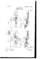
- Fig. 3 is a plan view, on a larger-scale, of the rear end of the center rail of the chain-frame and lthe front part yof the engine or motor platform.
- Fig. 4 is a longitudinal central secthere can be modification in many respects, although at present I prefer to employ a bed and carriage such as is illustrated in Patent No. 684,357, H. B. Dierdorf, dated October 8, 1901, among others, and reference can be made thereto for an understanding of the well-known details of these machines.
- the center rail 1 is at the rear end provided with a connecting device for joining it to the engine or motor frame, this being formed integrally with the rail l and by bending the latter upward, as shown in'Fig. 4.
- the platform 2 is formed with downwardlyeX- tending ribs 15, which have grooves or ways at 3, and in these are fitted the side edges of the rear end of the center rail.
- the chain passes around the driving-sprocket wheel above referred to, thence outward along one side of the chain-frame, around the front cross-head, and back to the driving-sprocket. It is frequently necessary to vary the tension of the chain-that is, to increase or decrease its slack. This. is accomplished by moving the chain-frame (including the center rail) backward orforward relatively to the engine-platform.
- Such movement has been generally effected by means of an adjusting screw-rod 4 and a nut 5.
- the nut 5 is a bolt or cylindrical body of relatively; large diameter, mounted vertically in the engine-platform. It passes through an aperture in the rear end of the center rail 1 and through a slot 5 in the engine-plate. If the nut 4 be turned, (as
- 6 is a bracing and connecting bar having a forward-projecting plate-ike part 16 an upwardly-bent part 17, and a head part 18.
- the forwardly-projecting part 16 is fastened to the center rail.
- the head part 1S is fastened to the inotor-platform.
- abutinents are bolts passing through a slot 12 in the plate 16.
- the slot permits a backward or forward adjustment of the chain-fraine, andv the bolts and nuts at 10 provide for firmly fastening the two parts together after adjustment.
- Figs. 5 and 6 I have shown a modification with respect to the brace and cross bar, the former in these figures being indicated by 6a and the latter by 7a.
- the cross-bar and brace here are integral, being preferably forged from one piece of metal.
- the crossbar is fastened by bolts 9a to the front fiange of the motor-platform.
- the details of the mechanism in Figs. 5 and 6 are or may be the saine as those in Figs. 3 and 4.
- the ways or grooves at 3 may be dispensed with, and, as these have generally required machine-work, the cost of the mechanism is considerably reduced. Where, however, great strength is necessary, the older plan can be followed.
- the rear end at 14 of the center rail should be braced laterally by'meansof ribs or their equivalent, such as shown at 15.
- the adjusting-screw 4 can be dispensed with when a bracing and connecting bar like that at 6 is present, although in others I prefer to use such screw as a power device for effecting the adjustment.
- a mining-machine of the class described, the combination of a motor platform or carrier, a cutter-frame having a central thrust-rail adjustable relatively to the motor-carrier and having its rear end loosely braced, and a connecting and bracing bar projecting forward from the motor-carrier and adjustably clamped to the said center rail of the cutter-carriage, substantially as set forth.
- a cutting apparatus having a center thrust-rail, an engine or motor platform or carrier having abutnients for the rear end of the center rail to hold it laterally in-relation to the motor-carrier, and a connecting and bracing bar eX- tending forward from the engine-carrier, and means for securing said bar to the center rail at either of several positions, substantially as described.
- a cutter-carrier having a central thrust-rail, an engine or motor platform or carrier having a guideway for the rear end of the center rail, a screwrod and nut interposed between the motorcarrier and the cutting apparatus for adjusting them relatively to each other, and a bracing and connecting bar supplemental to the aforesaid parts and interposed between the motor-carrier and the cutter-carrier, and means for securing said bar in either of sev- IOO IIO
- a cutter-carrier having a longitudinally-adjustable thrust-V bar, an engine or motor platform or carrier having laterally-acting abutinents for the rear end of the bar, a clamping device situ.- ated near the rear end of the said thrust-bar for connecting the motor-carrier and the cut- 6.
- a cutter-carrier having a longitudinally-arranged thrust-bar, an engine-platform or motor-carrier, a clamping-bolt at the rear end of the saidcuttercarrier and supported by one of the said carriers, the other of said carriers having a slot for the movement of the bolt, and a supplemental clamping-bolt su ported by one of said carriers at points in fiont of the motorcarrier, and a slotted bar for the said bolt supported by the other carrier, substantially as set forth.
- the combination of the cutter-carrier, the engine-platform or motorcarrier the .adjustable connecting means between the said carriers, the bracingplate extending forward from said motorcarrier and having a longitudinal slot therethrough, and a clamping-bolt extending through said slot and adapted to clamp the cutter-carrier to the said bracing-plate in various positions of adjustment.
Landscapes
- Engineering & Computer Science (AREA)
- Mechanical Engineering (AREA)
- Knives (AREA)
Description
PATBNTBD JAN. 2, 1906.
D. R. MURPHY. MINING MACHINE. APPLIGATION FILED PEB. zo. 1904.
2 SHEETS-SHEET l.
PATENTED JAN. 2, 1906.
2 SHEETS-SHEET 2 nunl;
Y www llo ncIJ I). R. MURPHY.
MINING MACHINE.
APPLICATION FILED PEB. 2o, 1904.
UNITED STATES PATENT OFFICE.
DANIEL R. MURPHY, OF SCENERY HILL, PENNSYLVANIA, ASSIGNOR TO JOSEPH A. JEFFREY, OF COLUMBUS, OHIO.
MINING-MACHINE.
Patented Jan. 2, 1906.
To @ZZ whom, t may concern:
Be it known that I, DANIEL R. MURPHY, a citizen of the United States, residing at Scenery Hill, in the county of I/Vashington and State of Pennsylvania, have invented certain new and useful Improvements in Mining- Machines, of which the following is a specification, reference being had therein to the accompanying drawings.
This invention relates to improvements in mining-machines, pertaining more particularly to improvements in machines of the class in which laterally-acting cutters are employed-that is to say, cutters which act while moving on lines transverse to their path of advance into the material that they are operating on. The cutting device commonly used in such machines is usually an endless chain provided at intervals with cutters, this chain being mounted upon a horizontally-arranged frame forming part of a carriage which is iitted to a bed and is adapted to move bodily forward and back while the chain is moving around it. It has been well known for a long time that to the cutting apparatus of this sort there is incident asevere lateral reaction, resulting in strains in a direction opposite to that followed by the working cutters. This reactionary thrust and the strains therefrom have been experienced principally by the devices which connect together the chain-frame and the engine or motor support.
The object of the present invention is to provide an improved construction and arrangement of parts for joining and bracing together the parts referred to.
Figure 1 is a plan view of the carriage of a mining-machine to which my improvements can be applied. Fig. 2 is a longitudinal section of the bed-frame and carriage. Fig. 3 is a plan view, on a larger-scale, of the rear end of the center rail of the chain-frame and lthe front part yof the engine or motor platform. Fig. 4 is a longitudinal central secthere can be modification in many respects, although at present I prefer to employ a bed and carriage such as is illustrated in Patent No. 684,357, H. B. Dierdorf, dated October 8, 1901, among others, and reference can be made thereto for an understanding of the well-known details of these machines. It is su'liicient here to state that the carriage B when the machine is in operation moves forward longitudinally on the bed A, the latter having guideways at C along its sides for the engine or motor platform and a guide at D for the central rail or main thrust-bar of the carriage. This center rail or thrust-bar is indicated by l, and 2 indicates the platform for the motor or engine and for the gearing which transmits power for the cutters and for moving the carriage forward and back. In machines having parts of the sort illustrated in the drawings the power for the cutters is transmitted through a shaft mounted in the bearing at 13, this shaft having at its lower end a sprocket-wheel in the horizontal plane of the major part of the thrust-bar or central rail. The center rail 1 is at the rear end provided with a connecting device for joining it to the engine or motor frame, this being formed integrally with the rail l and by bending the latter upward, as shown in'Fig. 4. The platform 2 is formed with downwardlyeX- tending ribs 15, which have grooves or ways at 3, and in these are fitted the side edges of the rear end of the center rail. The chain passes around the driving-sprocket wheel above referred to, thence outward along one side of the chain-frame, around the front cross-head, and back to the driving-sprocket. It is frequently necessary to vary the tension of the chain-that is, to increase or decrease its slack. This. is accomplished by moving the chain-frame (including the center rail) backward orforward relatively to the engine-platform. Such movement has been generally effected by means of an adjusting screw-rod 4 and a nut 5. The nut 5 is a bolt or cylindrical body of relatively; large diameter, mounted vertically in the engine-platform. It passes through an aperture in the rear end of the center rail 1 and through a slot 5 in the engine-plate. If the nut 4 be turned, (as
it can be by awrench applied to its head 4%) it will, through its thread engagement with the nut 5, cause the thrust-rail 1 to move backward or forwardvrelatively to the plat- IOO IOC
Preferablythese abutinents are bolts passing through a slot 12 in the plate 16. The slot permits a backward or forward adjustment of the chain-fraine, andv the bolts and nuts at 10 provide for firmly fastening the two parts together after adjustment.
lIn Figs. 5 and 6 I have shown a modification with respect to the brace and cross bar, the former in these figures being indicated by 6a and the latter by 7a. The cross-bar and brace here are integral, being preferably forged from one piece of metal. The crossbar is fastened by bolts 9a to the front fiange of the motor-platform. In other respects the details of the mechanism in Figs. 5 and 6 are or may be the saine as those in Figs. 3 and 4.
11 indicates a clamping or covering plate, it resting upon the front part of the bracebar 6 and covering the slot 12.
When the machine is provided with joining and connecting bracing devices of the character described, the ways or grooves at 3 may be dispensed with, and, as these have generally required machine-work, the cost of the mechanism is considerably reduced. Where, however, great strength is necessary, the older plan can be followed. In either case the rear end at 14 of the center rail should be braced laterally by'meansof ribs or their equivalent, such as shown at 15. In some cases also the adjusting-screw 4 can be dispensed with when a bracing and connecting bar like that at 6 is present, although in others I prefer to use such screw as a power device for effecting the adjustment.
What I claim is- 1. In a mining-machine ofthe class de' scribed, the combination with the motor platform or carrier having a guideway formed therein and a cutter-frame adjustable relatively to the motor-carrier and having its rear end tt'ed into said guideway of a connecting and bracing bar extending forward from the motor-carrier, and means for adjustably securing the said bar to the cutter-frame, substantially as set forth.
2. In a mining-machine, of the class described, the combination of a motor platform or carrier, a cutter-frame having a central thrust-rail adjustable relatively to the motor-carrier and having its rear end loosely braced, and a connecting and bracing bar projecting forward from the motor-carrier and adjustably clamped to the said center rail of the cutter-carriage, substantially as set forth.
3. In a mining-machine of the class described, the combination of a cutting apparatus having a center thrust-rail, an engine or motor platform or carrier having abutnients for the rear end of the center rail to hold it laterally in-relation to the motor-carrier, and a connecting and bracing bar eX- tending forward from the engine-carrier, and means for securing said bar to the center rail at either of several positions, substantially as described.
4. In a mining-machine of the class described, the combination of a cutter-carrier having a central thrust-rail, an engine or motor platform or carrier having a guideway for the rear end of the center rail, a screwrod and nut interposed between the motorcarrier and the cutting apparatus for adjusting them relatively to each other, and a bracing and connecting bar supplemental to the aforesaid parts and interposed between the motor-carrier and the cutter-carrier, and means for securing said bar in either of sev- IOO IIO
eral positions'relatively to the cutter-carrier,
substantially as set forth.
5. In a mining-machine of the, class described, the combination of a cutter-carrier having a longitudinally-adjustable thrust-V bar, an engine or motor platform or carrier having laterally-acting abutinents for the rear end of the bar, a clamping device situ.- ated near the rear end of the said thrust-bar for connecting the motor-carrier and the cut- 6. In a mining-machine of the class described, the combination of a cutter-carrier having a longitudinally-arranged thrust-bar, an engine-platform or motor-carrier, a clamping-bolt at the rear end of the saidcuttercarrier and supported by one of the said carriers, the other of said carriers having a slot for the movement of the bolt, and a supplemental clamping-bolt su ported by one of said carriers at points in fiont of the motorcarrier, and a slotted bar for the said bolt supported by the other carrier, substantially as set forth.
7. In a mining-machine, the combination of the cutter-carrying frame, the motor-platform having a guideway into which the rear end of said cutter-carrying frame is fitted, the adjusting means interposed between the said frame and the said platform, the bracing-bar extending forward from said Platform, and
means for adjustably connectlng said bracing-bar to the said cutter-carrying frame.
8. In a mining-machine, the combination of the motor-platform, the cutter-carrying frame adjustably connected to said platform, the bracing-bar extending forward from and detachably connected to said motor-platform, and the adjustable clamp between the said bracing-bar and the cutter-carrying frame.
9. In a mining-machine, the combination of the cutter-carrier, the engine-platform or motorcarrier the .adjustable connecting means between the said carriers, the bracingplate extending forward from said motorcarrier and having a longitudinal slot therethrough, and a clamping-bolt extending through said slot and adapted to clamp the cutter-carrier to the said bracing-plate in various positions of adjustment.
In testimony whereof I affix my signature in presence of two witnesses.
DANIEL R. MURPHY. Witnesses:
CLIFFORD PATTERSON, GEO. T; LINN.
Priority Applications (1)
| Application Number | Priority Date | Filing Date | Title |
|---|---|---|---|
| US19458604A US809206A (en) | 1904-02-20 | 1904-02-20 | Mining-machine. |
Applications Claiming Priority (1)
| Application Number | Priority Date | Filing Date | Title |
|---|---|---|---|
| US19458604A US809206A (en) | 1904-02-20 | 1904-02-20 | Mining-machine. |
Publications (1)
| Publication Number | Publication Date |
|---|---|
| US809206A true US809206A (en) | 1906-01-02 |
Family
ID=2877687
Family Applications (1)
| Application Number | Title | Priority Date | Filing Date |
|---|---|---|---|
| US19458604A Expired - Lifetime US809206A (en) | 1904-02-20 | 1904-02-20 | Mining-machine. |
Country Status (1)
| Country | Link |
|---|---|
| US (1) | US809206A (en) |
-
1904
- 1904-02-20 US US19458604A patent/US809206A/en not_active Expired - Lifetime
Similar Documents
| Publication | Publication Date | Title |
|---|---|---|
| US809206A (en) | Mining-machine. | |
| US368618A (en) | David e | |
| US2170888A (en) | Powered cross feed for lathes | |
| US945000A (en) | Mining-machine. | |
| US235824A (en) | Gang-saw mill | |
| US483156A (en) | Mining-machine | |
| US370119A (en) | brereton | |
| US391344A (en) | Cut-off sawing-machine | |
| US387757A (en) | baillie | |
| US139578A (en) | Improvement in machines for moving logs | |
| US598360A (en) | Mining maohineey | |
| US751919A (en) | Mining-machine | |
| US302766A (en) | Saw-sharpening machine | |
| US469260A (en) | mitchell | |
| US797018A (en) | Band-saw guide. | |
| US594898A (en) | Coal-cutting machine | |
| US1579704A (en) | Mining machine | |
| US347331A (en) | Machine for cutting veneers | |
| US1885520A (en) | Woodworking machine | |
| US630388A (en) | Mining-machine. | |
| US989285A (en) | Combination woodworking-machine. | |
| US656414A (en) | Mining-machine. | |
| US652387A (en) | Woodworking-machine. | |
| US801583A (en) | Coal-cutting machine. | |
| US145327A (en) | Improvement in saw-gumming machines |