US809202A - Mechanical stoker. - Google Patents
Mechanical stoker. Download PDFInfo
- Publication number
- US809202A US809202A US19094104A US1904190941A US809202A US 809202 A US809202 A US 809202A US 19094104 A US19094104 A US 19094104A US 1904190941 A US1904190941 A US 1904190941A US 809202 A US809202 A US 809202A
- Authority
- US
- United States
- Prior art keywords
- feed
- wing
- coal
- chamber
- recess
- Prior art date
- Legal status (The legal status is an assumption and is not a legal conclusion. Google has not performed a legal analysis and makes no representation as to the accuracy of the status listed.)
- Expired - Lifetime
Links
- 239000003245 coal Substances 0.000 description 27
- 239000000446 fuel Substances 0.000 description 4
- 238000005192 partition Methods 0.000 description 4
- 238000004891 communication Methods 0.000 description 2
- 230000006854 communication Effects 0.000 description 2
- 230000000694 effects Effects 0.000 description 2
- 238000010276 construction Methods 0.000 description 1
- 230000001276 controlling effect Effects 0.000 description 1
- 230000001419 dependent effect Effects 0.000 description 1
- 230000001066 destructive effect Effects 0.000 description 1
- 230000003467 diminishing effect Effects 0.000 description 1
- 239000012530 fluid Substances 0.000 description 1
- 230000001105 regulatory effect Effects 0.000 description 1
- 238000010008 shearing Methods 0.000 description 1
Images
Classifications
-
- F—MECHANICAL ENGINEERING; LIGHTING; HEATING; WEAPONS; BLASTING
- F23—COMBUSTION APPARATUS; COMBUSTION PROCESSES
- F23B—METHODS OR APPARATUS FOR COMBUSTION USING ONLY SOLID FUEL
- F23B40/00—Combustion apparatus with driven means for feeding fuel into the combustion chamber
- F23B40/04—Combustion apparatus with driven means for feeding fuel into the combustion chamber the fuel being fed from below through an opening in the fuel-supporting surface
-
- B—PERFORMING OPERATIONS; TRANSPORTING
- B65—CONVEYING; PACKING; STORING; HANDLING THIN OR FILAMENTARY MATERIAL
- B65G—TRANSPORT OR STORAGE DEVICES, e.g. CONVEYORS FOR LOADING OR TIPPING, SHOP CONVEYOR SYSTEMS OR PNEUMATIC TUBE CONVEYORS
- B65G2201/00—Indexing codes relating to handling devices, e.g. conveyors, characterised by the type of product or load being conveyed or handled
- B65G2201/02—Articles
Definitions
- ALBERT K. MANS- FIELD residing in Salem, Columbiana county, Ohio, (post-office address, No. 125 Lincoln avenue, Salem, Ohio,) and SAMUEL M. FEL- TON, residing in Chicago, Cook county, Illinois, (post-ofiice address, Grand Central station, Chicago, Illinois,) citizens of the United States, have invented certain new and useful Improvements in Mechanical Stokers, of which the following is a specification.
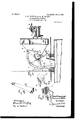
- FIG. 1 is a side elevation of a stoker exemplifying our invention, shown in connection with the feed-opening of an ordinary locomotive-boiler, a portion of one of the side plates of the stoker being broken away to exhibit the interior construction;
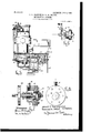
- Fig. 2 an end elevation of the feed-wing which effects the delivery of the coal into the fire-box Fig. 3, a perspective view of the feed-wing;
- Fig. 4 a perspective view of the deflector arranged in the discharge-nozzle to adjust the horizontal angle of discharge;
- Fig. 5 a front elevation, part vertical section, of the stoker;
- Fig. 6 a plan of the self-varying throttle-valve;
- Fig. 8 an elevation of the throttle with its bonnet removed.
- 1 indicates the fire-door opening of an ordinary locomotive-boiler; 2, an escutcheon-plate rigidly secured thereat; 3, the nozzle of the stoker projecting through the escutcheon plate and into the dooropening; 4, a circular feed-chamber to which the nozzle is tangent; 5, a feed-wing mounted for rotation in the feed-chamber 5, an axial recess or pocket in the hub of the feed-wing; 5", an end wall to this pocket, whose opposite end is open 6, a hopper delivering into the feed-chamber at the center of one of its side walls; 7, a short conveyer at the foot of the hopper to facilitate the passage of the coal from the hopper into the feed-chamber and to effect to some extent the regulation of the discharge of coal into the feed-chamber; 8, an engine whose shaft is the shaft of the feedwing, the illustration showing a double engine with its cranks set quartering, this engine being merely typical of a suitable mo:
- wing 5'compr1 ses a hub and a blade portion.
- the coal from the hopper enters the feedchamber 4 horizontally at the center of the chamber, the passage of the coal being facilitated and regulated by the conveyer 7.
- the entering coal goes aXially'into the pocket of the feed-wing hub and is dumped by it into the lower portion of the feed-chamber, Where it is acted upon by the wing-blade and thrown into the furnace with a speed that is regu larly increasing or diminishing successively. There is thus no destructive shearing action upon the coal between the feed-wing and the margin of the passage leading the coal into the chamber.
- the end wall 5 of the pocket of the feed-wing prevents the coal from reaching the farther wall of the chamber and getting between that wall and the hub of the feed-wing.
- the coal enters the feedchamber 4 in an obvious manner and the feed-wing dashes it into the fire-box.
- the distance to which the coal will be thrown into the fire-box will be dependent upon the velocity with which the feed-wing is turning, and in order that the delivery upon the grate may be distributed in a foreand-aft direction provision is made for automatically and continuously altering the speed of the motor, so that the coal will be thrown at one time at a near point on the grate, then farther inwardly, then still farther inwardly, then less far inwardly, and so on, a distribution being thus effected from the front to the back of the grate. This is accomplished by means of the self-varying throttle-valve.
- the discharge of coal would be in a general direction straight outward from the nozzle; but by angularly adjusting the deflecting-rib 23 the delivery of coal may be deflected laterally, by which means a satisfactory sidewise distribution of the coal may be efiected and the delivery may be specially directed to thin places in the fire.
- a stoker the combination, substantially as set forth, of a circular feed-chamber having a tangential nozzle and having a central feed-opening through one of its sides, a supplyhopper communicating with said feedopening, a rotary feed-wing mounted in said feed-chamber and having a recess in axial prolongation of said feed-opening, and mechanism for rotating the feed-wing.
- a stoker the combination, substantially as set forth, of a circular feed-chamber having a tangential nozzle and having a central feed-opening through one of its sides, a supply-hopper communicating with said feedopening, a rotary feed-wing mounted in said f eed-chamber and having a recess in axial prolongation ofsaid feed-opening, mechanism for rotating the feed-wing, and an angularly-adjustable deflecting-rib mounted in said nozzle.
- a mechanical stoker the combination, substantially as set forth, of a circular feed-chamber having a tangential discharge nozzle, a feed-wing having an axial recess mounted for rotation in the feed-chamber, a feed-hopper having communication with the central portion of the feedchamber and arranged to feed endwise into the axial recess of the feed-wing, a conveyer at the juncture of the hopper and feed-chamber, and mechanism for giving motion to said wing and to said conveyer.
- a mechanical stoker the combination, substantially as set forth, of a feedchamber having a discharge-nozzle, a feedhopper arranged to deliver coal thereto, a rotary discharge device mounted upon a horizontal axis within the feed-ch amber to expel the coal therefrom into the furnace, a fluidpressure motor for rotating the discharge device continuously, a throttle-valve provided with a variable opening controlling the sup ply of fluid to said motor, and mechanism operated by the motor to actuate said throttle-valve, whereby the speed of rotation of said' discharge device is automatically subjected to successive changes.
- a feed chamber having a horizontal discharge-nozzle at its base, a rotary wing provided with an axial recess and mounted for rotation in said feedchamber, a feed-hopper having communica tion with the central portion of the feedchamber and arranged to feed endwise into the axial recess of said wing, a motor, transmittingmechanism between the motor and said wing, and additional transmitting connections from the motor adapted to be'connected with the shaking-grate.
- a feed-wing provided with a hub and blade mounted for rotation upon a horizontal axis and having at its hub an axial recess with an opening opposite the blade, and means for delivering coal into said recess and for guiding the coal when dumped from the recess and acted upon by the wing.
- a mechanical stoker the combination, substantially as set forth, of a feed-wing provided with a hub and blade mounted for rotation upon a horizontal axis and having at its hub an axial recess with an end wall and with an opening opposite the blade, and means for delivering coal into said recess and for guiding the coal when dumped from the recess and acted upon by the wing.
- a mechanical stoker the combination substantially as set forth, of a feed-wing provided with a hub and blade mounted for rotation upon a horizontal axis and having at its hub an axial recess with an openingat one end and with an opening opposite the blade, and means for delivering coal endWise into said recess and for guiding the coal when dumped from the recess and acted upon by the wing.
- a feed-wing provided with a hub and blade mounted for rotation upon a horizontal axis and having at its hub an axial recess open at one end and side, and a chamber inclosing said wing and having an inlet to deliver coal to said recess and an outlet for coal dumped from said recess and acted upon by the wing.
- a mechanical stoker the combination, substantially as set forth, of a feedchamber having a horizontal discharge-nozzle at its base and having afeed-openingleading into its side, a conveyer disposed within said feed-opening, a rotary shaft, and a wing carried by said shaft within said feed-chamber and having an axial recess communicating with said feed-opening and adapted to receive the fuel advanced therethrough by the conveyer, the inner wall of said axial recess coinciding substantially with the margin of said feed-opening 11.
- a mechanical stoker the combination, substantially as set forth, of a feedchamber having an outlet and a feed-opening, a rotary shaft, and a feed-wing carried by said shaft and disposed within said chamber and having its inner portion disposed at such radial distance from the axial line of the shaft as to provide the wing with an axial recess within the field swept through by said wing, said axial line being arranged to receive fuel entering through said feedopening.
- a mechanical stoker the combination, substantially as set forth, of a feedchamber having a feed-opening leading into one of its sides, a rotary conveyer mounted at said feed-opening and adapted to feed fuel therethrough, a shaft mounted in the side of the feed-chamber opposite the conveyer and in axial line therewith, and a feed-wing having an axial recess carried by the shaft within the chamber.
- a mechanical stoker the combination, substantially as set forth, of a feedchamber having a horizontal discharge-nozzle and having a feed-opening leading into one of its sides, a shaft mounted in the chamber in axial alinement with said feed-opening, and a rotary wing disposed within the feed-chamber and carried by said shaft and having its inner portion at a distance from the common axial line of the shaft and feedopening, whereby said wing is provided with an axial recess surrounded by the field swept through by said feed-wing,said axial recess being arranged to receive fuel entering through said feed-opening.
Landscapes
- Engineering & Computer Science (AREA)
- Physics & Mathematics (AREA)
- Chemical & Material Sciences (AREA)
- Combustion & Propulsion (AREA)
- Thermal Sciences (AREA)
- Mechanical Engineering (AREA)
- General Engineering & Computer Science (AREA)
- Filling Or Emptying Of Bunkers, Hoppers, And Tanks (AREA)
Description
No 809,202. PATENTED JAN. 2, 1906. A. K. MANSFIELD & S. M. FELTON MECHANICAL STOKER.
APPLICATION FILED JAN. 23. 1904.
2 SHEETS-SHBET 1.
I IIlIIlIIIIIIIIIIIIl/le Witnesses: Inventors (l umm.s v w, $1 W 5W M Attorney PATENTED JAN. 2, 1906. A. K. MANSFIELD & S. M. FBLTON.
MECHANICAL STOKER. APPLICATION I'I'LED JAN. 28. '1904.
2 SHEETS 3HEET Witnesses M02 ventors Attorney mwmmm UNITED STATES PATENT OFFICE.
ALBERT K. MANSFIELD, OF SALEM, OHIO, AND SAMUEL M. FELTON, OF CHICAGO, ILLINOIS.
MECHANICAL STOKER.
Specification of Letters Patent.
Patented Jan. 2, 1906.
Application filed January 28, 1904. Serial No. 190,941.
To all whom it may concern.-
Be it known that we, ALBERT K. MANS- FIELD, residing in Salem, Columbiana county, Ohio, (post-office address, No. 125 Lincoln avenue, Salem, Ohio,) and SAMUEL M. FEL- TON, residing in Chicago, Cook county, Illinois, (post-ofiice address, Grand Central station, Chicago, Illinois,) citizens of the United States, have invented certain new and useful Improvements in Mechanical Stokers, of which the following is a specification.
This invention, pertaining to improvements in mechanical stokers, will be readily understood from the following description, taken in connection with the accompanying drawings, in which Figure 1 is a side elevation of a stoker exemplifying our invention, shown in connection with the feed-opening of an ordinary locomotive-boiler, a portion of one of the side plates of the stoker being broken away to exhibit the interior construction; Fig. 2, an end elevation of the feed-wing which effects the delivery of the coal into the fire-box Fig. 3, a perspective view of the feed-wing; Fig. 4, a perspective view of the deflector arranged in the discharge-nozzle to adjust the horizontal angle of discharge; Fig. 5, a front elevation, part vertical section, of the stoker; Fig. 6, a plan of the self-varying throttle-valve; Fig. 7, a vertical section of the throttle, and Fig. 8 an elevation of the throttle with its bonnet removed.
In the drawings, 1 indicates the fire-door opening of an ordinary locomotive-boiler; 2, an escutcheon-plate rigidly secured thereat; 3, the nozzle of the stoker projecting through the escutcheon plate and into the dooropening; 4, a circular feed-chamber to which the nozzle is tangent; 5, a feed-wing mounted for rotation in the feed-chamber 5, an axial recess or pocket in the hub of the feed-wing; 5", an end wall to this pocket, whose opposite end is open 6, a hopper delivering into the feed-chamber at the center of one of its side walls; 7, a short conveyer at the foot of the hopper to facilitate the passage of the coal from the hopper into the feed-chamber and to effect to some extent the regulation of the discharge of coal into the feed-chamber; 8, an engine whose shaft is the shaft of the feedwing, the illustration showing a double engine with its cranks set quartering, this engine being merely typical of a suitable mo:
tor for giving motion to the moving parts of the device; 9, a ratchet-wheel on the shaft of the conveyer; 10, an eccentric-pin carried by the engine-shaft; 11, a rock-shaft; 12, a pawl arm with a pawl cooperating with ratchet-wheel 9; 12, the pawl carried by this arm 13,- link-and-arm work connecting the rock-shaft with the eccentric-pin and with pawl-arm 12, whereby the rotation of the engine-shaf t gives intermittent motion to the conveyer; 14, a special self-varying throttle-valve for the engine; 15, the steam-supplypipe to the throttle-valve; 16, the steampipe from the throttle-valve to the engine; 17, a partition between the two pipes 15 and 16; 18, a series of holes through this partition; 19, a plate cooperating with the partition and serving as it rotates to cover a greater or less number of the holesjthrough the partition; 20, a ratchet-wheel on the spindle of disk 19; 21, a pawl-arm and pawl cooperating with ratchet-wheel 20; 21, the pawl just referred to; 22, a link connecting eccentric-pin 10 with pawl-arm 21, whereby the rotation of the engine-shaft gives step-bystep rotation to throttle-disk 19; 23, a deflecting-rib extending fore and aft of the coaldischarge nozzle 3, this deflecting-rib being disposed upon the floor of the nozzle and pivoted at one end so that it may be angularly adjusted upon the floor; 24, an adjusting-bar connected with the free end of the deflectingrib and serving as means for adjusting it, the illustration showing this adjusting-bar as being provided with a detent-pin to hold it in selected position; 24, the detent-pin; and 25 a link extending downwardly from the pawlarm of the conveyer, which may, if desired, be employed in giving motion to a shakinggrate if such. grate be employed in connection with the stoker.
It will be noted that the wing 5'compr1ses a hub and a blade portion.
The coal from the hopper enters the feedchamber 4 horizontally at the center of the chamber, the passage of the coal being facilitated and regulated by the conveyer 7. The entering coal goes aXially'into the pocket of the feed-wing hub and is dumped by it into the lower portion of the feed-chamber, Where it is acted upon by the wing-blade and thrown into the furnace with a speed that is regu larly increasing or diminishing successively. There is thus no destructive shearing action upon the coal between the feed-wing and the margin of the passage leading the coal into the chamber. The end wall 5 of the pocket of the feed-wing prevents the coal from reaching the farther wall of the chamber and getting between that wall and the hub of the feed-wing.
The coal enters the feedchamber 4 in an obvious manner and the feed-wing dashes it into the fire-box. The distance to which the coal will be thrown into the fire-box will be dependent upon the velocity with which the feed-wing is turning, and in order that the delivery upon the grate may be distributed in a foreand-aft direction provision is made for automatically and continuously altering the speed of the motor, so that the coal will be thrown at one time at a near point on the grate, then farther inwardly, then still farther inwardly, then less far inwardly, and so on, a distribution being thus effected from the front to the back of the grate. This is accomplished by means of the self-varying throttle-valve. As the disk rotates its segment first uncovers but few of the holes 18, thus resulting in a comparatively slow motion of the motor and in a comparatively gentle delivery of the coal upon the grate, the continued rotation of the disk effecting a more liberal supply of steam to the motor, resulting in a more violent and more distant discharge of the coal until the segment has uncovered all the holes and has given the engine its maximum quantity of steam, after which it begins to close the openings and reduce the speed of the engine, and so on and on. The segment of the disk is incapable of completely closing the entire series of openings at one time, and thus cannot entirely shut off all the steam and stop the motor. The discharge of coal would be in a general direction straight outward from the nozzle; but by angularly adjusting the deflecting-rib 23 the delivery of coal may be deflected laterally, by which means a satisfactory sidewise distribution of the coal may be efiected and the delivery may be specially directed to thin places in the fire.
-We claim as our invention 1. In a stoker, the combination, substantially as set forth, of a circular feed-chamber having a tangential nozzle and having a central feed-opening through one of its sides, a supplyhopper communicating with said feedopening, a rotary feed-wing mounted in said feed-chamber and having a recess in axial prolongation of said feed-opening, and mechanism for rotating the feed-wing.
2. In a stoker, the combination, substantially as set forth, of a circular feed-chamber having a tangential nozzle and having a central feed-opening through one of its sides, a supply-hopper communicating with said feedopening, a rotary feed-wing mounted in said f eed-chamber and having a recess in axial prolongation ofsaid feed-opening, mechanism for rotating the feed-wing, and an angularly-adjustable deflecting-rib mounted in said nozzle.
In a mechanical stoker, the combination, substantially as set forth, of a circular feed-chamber having a tangential discharge nozzle, a feed-wing having an axial recess mounted for rotation in the feed-chamber, a feed-hopper having communication with the central portion of the feedchamber and arranged to feed endwise into the axial recess of the feed-wing, a conveyer at the juncture of the hopper and feed-chamber, and mechanism for giving motion to said wing and to said conveyer.
4. In a mechanical stoker, the combination, substantially as set forth, of a feedchamber having a discharge-nozzle, a feedhopper arranged to deliver coal thereto, a rotary discharge device mounted upon a horizontal axis within the feed-ch amber to expel the coal therefrom into the furnace, a fluidpressure motor for rotating the discharge device continuously, a throttle-valve provided with a variable opening controlling the sup ply of fluid to said motor, and mechanism operated by the motor to actuate said throttle-valve, whereby the speed of rotation of said' discharge device is automatically subjected to successive changes.
5. The combination of a feed chamber having a horizontal discharge-nozzle at its base, a rotary wing provided with an axial recess and mounted for rotation in said feedchamber, a feed-hopper having communica tion with the central portion of the feedchamber and arranged to feed endwise into the axial recess of said wing, a motor, transmittingmechanism between the motor and said wing, and additional transmitting connections from the motor adapted to be'connected with the shaking-grate.
6. In a mechanical stoker, the combination, substantially as set forth, of a feed-wing provided with a hub and blade mounted for rotation upon a horizontal axis and having at its hub an axial recess with an opening opposite the blade, and means for delivering coal into said recess and for guiding the coal when dumped from the recess and acted upon by the wing.
7. In a mechanical stoker, the combination, substantially as set forth, of a feed-wing provided with a hub and blade mounted for rotation upon a horizontal axis and having at its hub an axial recess with an end wall and with an opening opposite the blade, and means for delivering coal into said recess and for guiding the coal when dumped from the recess and acted upon by the wing.
8. In a mechanical stoker, the combination substantially as set forth, of a feed-wing provided with a hub and blade mounted for rotation upon a horizontal axis and having at its hub an axial recess with an openingat one end and with an opening opposite the blade, and means for delivering coal endWise into said recess and for guiding the coal when dumped from the recess and acted upon by the wing.
9. In a mechanical stoker, the combination, substantially as set forth, of a feed-wing provided with a hub and blade mounted for rotation upon a horizontal axis and having at its hub an axial recess open at one end and side, and a chamber inclosing said wing and having an inlet to deliver coal to said recess and an outlet for coal dumped from said recess and acted upon by the wing.
10. In a mechanical stoker, the combination, substantially as set forth, of a feedchamber having a horizontal discharge-nozzle at its base and having afeed-openingleading into its side, a conveyer disposed within said feed-opening, a rotary shaft, and a wing carried by said shaft within said feed-chamber and having an axial recess communicating with said feed-opening and adapted to receive the fuel advanced therethrough by the conveyer, the inner wall of said axial recess coinciding substantially with the margin of said feed-opening 11. In a mechanical stoker, the combination, substantially as set forth, of a feedchamber having an outlet and a feed-opening, a rotary shaft, and a feed-wing carried by said shaft and disposed within said chamber and having its inner portion disposed at such radial distance from the axial line of the shaft as to provide the wing with an axial recess within the field swept through by said wing, said axial line being arranged to receive fuel entering through said feedopening.
12. In a mechanical stoker, the combination, substantially as set forth, of a feedchamber having a feed-opening leading into one of its sides, a rotary conveyer mounted at said feed-opening and adapted to feed fuel therethrough, a shaft mounted in the side of the feed-chamber opposite the conveyer and in axial line therewith, and a feed-wing having an axial recess carried by the shaft within the chamber.
13. In a mechanical stoker, the combination, substantially as set forth, of a feedchamber having a horizontal discharge-nozzle and having a feed-opening leading into one of its sides, a shaft mounted in the chamber in axial alinement with said feed-opening, and a rotary wing disposed within the feed-chamber and carried by said shaft and having its inner portion at a distance from the common axial line of the shaft and feedopening, whereby said wing is provided with an axial recess surrounded by the field swept through by said feed-wing,said axial recess being arranged to receive fuel entering through said feed-opening. v
ALBERT K. MANSFIELD. SAMUEL M. FELTON. Witnesses as to Mansfield:
HAROLD T. VAN BUREN, ATTILIO PIATTI.
Witnesses as to Felton: W. G. LEROH, G. C. DEANE.
Priority Applications (1)
| Application Number | Priority Date | Filing Date | Title |
|---|---|---|---|
| US19094104A US809202A (en) | 1904-01-28 | 1904-01-28 | Mechanical stoker. |
Applications Claiming Priority (1)
| Application Number | Priority Date | Filing Date | Title |
|---|---|---|---|
| US19094104A US809202A (en) | 1904-01-28 | 1904-01-28 | Mechanical stoker. |
Publications (1)
| Publication Number | Publication Date |
|---|---|
| US809202A true US809202A (en) | 1906-01-02 |
Family
ID=2877683
Family Applications (1)
| Application Number | Title | Priority Date | Filing Date |
|---|---|---|---|
| US19094104A Expired - Lifetime US809202A (en) | 1904-01-28 | 1904-01-28 | Mechanical stoker. |
Country Status (1)
| Country | Link |
|---|---|
| US (1) | US809202A (en) |
-
1904
- 1904-01-28 US US19094104A patent/US809202A/en not_active Expired - Lifetime
Similar Documents
| Publication | Publication Date | Title |
|---|---|---|
| US749206A (en) | Fuel-feeding device | |
| US809202A (en) | Mechanical stoker. | |
| US2163706A (en) | Air control for blowers for automatic stokers | |
| US391873A (en) | Furnace-feeder | |
| US578630A (en) | Mechanical stoking apparatus | |
| US1203703A (en) | Pulverized-coal-feeding apparatus. | |
| US1231327A (en) | Apparatus for feeding pulverized fuel. | |
| US2158673A (en) | Overfeed stoker | |
| US813022A (en) | Charging-machine. | |
| US1897510A (en) | Locomotive stoker | |
| US1885203A (en) | Mechanical stoker | |
| US797100A (en) | Conveying mechanism. | |
| US684153A (en) | Apparatus for feeding pulverized fuel to a plurality of fire-boxes. | |
| US307552A (en) | jenkins | |
| US707364A (en) | Heating apparatus. | |
| US547597A (en) | Allen | |
| US542477A (en) | Feeding shavings to furnaces | |
| US1048756A (en) | Stoker. | |
| US1267681A (en) | Mechanical stoker. | |
| US1142364A (en) | Fuel-feeding apparatus. | |
| US524579A (en) | Fuel-feeding device | |
| US414322A (en) | Coal-dust feeder | |
| US242771A (en) | Mechanical stoker | |
| US713191A (en) | Mechanical stoker. | |
| US831145A (en) | Fuel-feeding apparatus. |