US8091950B2 - Methods and apparatus for reducing drag via a plasma actuator - Google Patents

Methods and apparatus for reducing drag via a plasma actuator Download PDF

Info

Publication number
US8091950B2
US8091950B2 US11/934,272 US93427207A US8091950B2 US 8091950 B2 US8091950 B2 US 8091950B2 US 93427207 A US93427207 A US 93427207A US 8091950 B2 US8091950 B2 US 8091950B2
Authority
US
United States
Prior art keywords
plasma
fluid flow
generating device
ground vehicle
plasma generating
Prior art date
Legal status (The legal status is an assumption and is not a legal conclusion. Google has not performed a legal analysis and makes no representation as to the accuracy of the status listed.)
Active
Application number
US11/934,272
Other versions
US20080122252A1 (en
Inventor
Thomas C. Corke
Richard Spivey
Current Assignee (The listed assignees may be inaccurate. Google has not performed a legal analysis and makes no representation or warranty as to the accuracy of the list.)
University of Notre Dame
Original Assignee
University of Notre Dame
Priority date (The priority date is an assumption and is not a legal conclusion. Google has not performed a legal analysis and makes no representation as to the accuracy of the date listed.)
Filing date
Publication date
Priority to EP07854573A priority Critical patent/EP2084060A2/en
Priority to US11/934,272 priority patent/US8091950B2/en
Priority to PCT/US2007/083488 priority patent/WO2008058011A2/en
Priority to AU2007317415A priority patent/AU2007317415A1/en
Priority to CA002668450A priority patent/CA2668450A1/en
Application filed by University of Notre Dame filed Critical University of Notre Dame
Assigned to THE UNIVERSITY OF NORTE DAME DU LAC reassignment THE UNIVERSITY OF NORTE DAME DU LAC ASSIGNMENT OF ASSIGNORS INTEREST (SEE DOCUMENT FOR DETAILS). Assignors: CORKE, THOMAS C.
Publication of US20080122252A1 publication Critical patent/US20080122252A1/en
Assigned to UNIVERSITY OF NOTRE DAME DU LAC reassignment UNIVERSITY OF NOTRE DAME DU LAC ASSIGNMENT OF ASSIGNORS INTEREST (SEE DOCUMENT FOR DETAILS). Assignors: SPIVEY, RICHARD
Application granted granted Critical
Publication of US8091950B2 publication Critical patent/US8091950B2/en
Active legal-status Critical Current
Anticipated expiration legal-status Critical

Links

Images

Classifications

    • BPERFORMING OPERATIONS; TRANSPORTING
    • B64AIRCRAFT; AVIATION; COSMONAUTICS
    • B64CAEROPLANES; HELICOPTERS
    • B64C23/00Influencing air flow over aircraft surfaces, not otherwise provided for
    • B64C23/005Influencing air flow over aircraft surfaces, not otherwise provided for by other means not covered by groups B64C23/02 - B64C23/08, e.g. by electric charges, magnetic panels, piezoelectric elements, static charges or ultrasounds
    • BPERFORMING OPERATIONS; TRANSPORTING
    • B62LAND VEHICLES FOR TRAVELLING OTHERWISE THAN ON RAILS
    • B62DMOTOR VEHICLES; TRAILERS
    • B62D35/00Vehicle bodies characterised by streamlining
    • BPERFORMING OPERATIONS; TRANSPORTING
    • B62LAND VEHICLES FOR TRAVELLING OTHERWISE THAN ON RAILS
    • B62DMOTOR VEHICLES; TRAILERS
    • B62D35/00Vehicle bodies characterised by streamlining
    • B62D35/001For commercial vehicles or tractor-trailer combinations, e.g. caravans
    • HELECTRICITY
    • H05ELECTRIC TECHNIQUES NOT OTHERWISE PROVIDED FOR
    • H05HPLASMA TECHNIQUE; PRODUCTION OF ACCELERATED ELECTRICALLY-CHARGED PARTICLES OR OF NEUTRONS; PRODUCTION OR ACCELERATION OF NEUTRAL MOLECULAR OR ATOMIC BEAMS
    • H05H1/00Generating plasma; Handling plasma
    • H05H1/24Generating plasma
    • H05H1/2406Generating plasma using dielectric barrier discharges, i.e. with a dielectric interposed between the electrodes
    • H05H1/2439Surface discharges, e.g. air flow control
    • BPERFORMING OPERATIONS; TRANSPORTING
    • B64AIRCRAFT; AVIATION; COSMONAUTICS
    • B64CAEROPLANES; HELICOPTERS
    • B64C2230/00Boundary layer controls
    • B64C2230/12Boundary layer controls by using electromagnetic tiles, fluid ionizers, static charges or plasma
    • FMECHANICAL ENGINEERING; LIGHTING; HEATING; WEAPONS; BLASTING
    • F05INDEXING SCHEMES RELATING TO ENGINES OR PUMPS IN VARIOUS SUBCLASSES OF CLASSES F01-F04
    • F05DINDEXING SCHEME FOR ASPECTS RELATING TO NON-POSITIVE-DISPLACEMENT MACHINES OR ENGINES, GAS-TURBINES OR JET-PROPULSION PLANTS
    • F05D2270/00Control
    • F05D2270/01Purpose of the control system
    • F05D2270/17Purpose of the control system to control boundary layer
    • F05D2270/172Purpose of the control system to control boundary layer by a plasma generator, e.g. control of ignition
    • YGENERAL TAGGING OF NEW TECHNOLOGICAL DEVELOPMENTS; GENERAL TAGGING OF CROSS-SECTIONAL TECHNOLOGIES SPANNING OVER SEVERAL SECTIONS OF THE IPC; TECHNICAL SUBJECTS COVERED BY FORMER USPC CROSS-REFERENCE ART COLLECTIONS [XRACs] AND DIGESTS
    • Y02TECHNOLOGIES OR APPLICATIONS FOR MITIGATION OR ADAPTATION AGAINST CLIMATE CHANGE
    • Y02TCLIMATE CHANGE MITIGATION TECHNOLOGIES RELATED TO TRANSPORTATION
    • Y02T50/00Aeronautics or air transport
    • Y02T50/10Drag reduction

Abstract

A vehicle includes a surface over which airflow passes. A plasma actuator is configured to generate plasma above the surface, the plasma coupling a directed momentum into the air surrounding the surface to reduce separation of the airflow from the surface. A method of reducing separation of airflow from a surface of the vehicle includes generating plasma in air surrounding the surface at a position where the airflow would separate from the surface in the absence of the plasma.

Description

CROSS REFERENCE TO RELATED APPLICATION
This application is a non-provisional application claiming priority from U.S. Provisional Application Ser. No. 60/856,871, filed Nov. 2, 2006, entitled “Truck Tractor and Trailer Aerodynamic Drag Reduction Using Single Dielectric Barrier Discharge (SDBD) Plasma Actuators” and incorporated herein by reference in its entirety.
FIELD OF THE DISCLOSURE
The present disclosure relates generally to drag reduction, and more particularly, to methods and apparatus for reducing drag via a plasma actuator.
BACKGROUND OF RELATED ART
Trucks, such as for example, class-8 heavy duty trucks typically use significant amounts of fuel to move cargo across the nation. In most instances, very little attention has been paid to the major drag-producing design with the exception of a passive fairing placed over the tractor top and/or side to help close the gap between tractor and trailer. Separated flow typically exists over many of the surfaces to include the tractor-trailer gap, the rear end of the trailer and all along the under-carriage of the rig. It is known that overcoming the effects of drag oftentimes can require as much as two-thirds of the engine's power at a cruise speed of 70 miles per hour. Accordingly, class-8 truck gas mileage has not changed much in 15 years, and it is typically still between 5.5 and 6.5 miles per gallon. While some improvement has been made in efficiency, most of the gains have been negated by increases in cruise speed and higher gross weight limits. The use of an active flow control by plasma actuators can reduce the areas of separated flow which can make significant gains in rig efficiency, lowering the power and fuel consumption and improving the environmental emissions.
Previous efforts to reduce the drag of these rigs have made some improvements, but so far have been slow to gain acceptance into the fleets because they interfere with the utility of the vehicle, require extensive power, are expensive modifications, show small improvements in fuel consumption and/or are not structurally sound enough to handle the day-to-day rough conditions that these vehicles experience. Some improvements have included fairings below the trailer body between the wheels, extension of the aft end of the trailer, and high speed injection of air into the flow.
Plasma actuators have no moving parts, require very little power, can be incorporated into fairings and basic tractor and trailer structure, and show promise to greatly reduce the power and fuel consumption. They can be painted over and not even be seen by the casual observer.
Plasma flow actuators provide a “body force” to the flow as the air passes over the surface. This “body force” accelerates the air, stabilizing the boundary layer and causing the air to remain attached to the surface even around tight radii to reduce or eliminate separated flow, a source of drag. By placing these actuators on the surface just before where the flow would ordinarily separate, the flow will remain attached which reduces drag.
In one example, plasma actuators may be placed on fairings over the aft doors of the trailer to coax the flow around the corners, greatly reducing the turbulence and vortices behind these rigs. In another example, fairings may be incorporated into the doors for new trailers, and in yet another example, the same concept may be applied to the aft part of the tractor to cause the flow to stay attached behind the tractor. In still other examples, the forward part of the trailer may have actuators on its leading corners to keep the flow attached along the sides and top. In each of these examples, the gap-drag may thus be minimized leading to additional fuel savings.
In another example, plasma actuators may be applied to the under-carriage of a vehicle to contain the flow and maintain attachment to assist in drag reduction. Still further, in each of the disclosed examples, the actuators may be turned off whenever the driver applies the brakes, to allow the drag to increase, thereby slowing the vehicle and reducing the braking needed.
BRIEF DESCRIPTION OF THE DRAWINGS
FIG. 1 is a cross-sectional schematic illustration of an example single dielectric barrier discharge plasma actuator for use in reducing drag.
FIGS. 2 a and 2 b are schematic illustrations of the example single dielectric barrier discharge plasma actuator of FIG. 1 during half-cycles of an applied voltage waveform.
FIG. 2 c is a schematic illustration of a photomultiplier tube arrangement used to measure light emissions from an example plasma actuator.
FIG. 2 d is an illustration of an example light emission from an example plasma actuator as a function of the applied voltage.
FIG. 2 e is an illustration of an example light emission from an example plasma actuator as a function of the applied current.
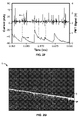
FIG. 2 f is an illustration of an example light emission from the plasma actuator of FIG. 2 e.
FIG. 2 g is a photograph of the plasma generated by an example plasma actuator.
FIG. 2 h is an illustration of the time to first light of the plasma as a function of the lateral (chordwise) distance of an example plasma actuator.
FIG. 2 i is a surface plot of the light emission of an example plasma actuator.
FIG. 3 is circuit model of the example plasma actuator of FIG. 1.
FIGS. 4 a and 4 b are schematic depictions of frequency and amplitude optimization, respectively, of an example plasma actuator.
FIG. 5 a is an illustration of positive and negative sawtooth voltage waveforms applied to an example plasma actuator.
FIG. 5 b is an illustration of positive and negative sawtooth current waveforms, corresponding to the positive and negative sawtooth voltage waveforms of FIG. 5 a, applied to an example plasma actuator.
FIG. 5 c is an illustration of the light emission from an example plasma actuator for the example of the applied positive sawtooth voltage waveform of FIG. 5A.
FIG. 5 d is an illustration of the light emission from an example plasma actuator for the example of the applied negative sawtooth voltage waveform of FIG. 5A.
FIG. 5 e is an illustration of the thrust versus dissipated power of an example plasma actuator for both the applied positive and negative sawtooth voltage waveforms.
FIG. 5 f is an illustration of power dissipated in the plasma generated by an example plasma actuator.
FIGS. 5 g and 5 h illustrate the induced velocity of air versus applied voltage for a square waveform and a triangle waveform, respectively when applied to an example plasma actuator.
FIG. 5 i illustrates the linear additive effect of an example plasma actuator.
FIG. 5 j is a smoke visualization of a cylinder showing the typical airflow around the cylinder.
FIG. 5 k is a smoke visualization of the cylinder of FIG. 5 j, showing the energization of two example plasma actuators located on the diameter of the cylinder.
FIG. 6 a illustrates an example class-8 truck for use with the example plasma actuator of FIG. 1.
FIG. 6 b illustrates where on the example tractor and trailer the example plasma actuator of FIG. 1 may effect drag.
FIG. 7 a illustrates an example of airflow behind a tractor or trailer while cruising at typical highway speeds.
FIG. 7 b illustrates an example configuration of plasma actuators mounted on a fairing attached to the back of the tractor or trailer.
FIG. 8 a is a smoke visualization of airflow around a four-inch radius surface in a wind tunnel without plasma actuators operating.
FIG. 8 b is a smoke visualization of airflow around the four-inch radius surface of FIG. 8 a with an example plasma actuator operating at a voltage of 28.5 kilovolts.
FIG. 9 illustrates results showing the separation angle of the airflow as a function of radius, velocity of the airflow, and voltage of the plasma actuator, in an example wind tunnel test.
DETAILED DESCRIPTION
The following description of various examples is not intended to limit the scope of the invention to the precise form or forms detailed herein. Instead, the following description is intended to be illustrative of the principles of the disclosure so that others may follow its teachings.
Referring to FIG. 1, an example single-dielectric barrier discharge (SDBD) plasma actuator 1 is attached to a surface 3, such as a fairing and/or a vehicle as will be described below. The actuator 1 may be attached to the surface such as, in particular, any region in which airflow separates from the surface 3. The example plasma actuator 1 includes an exposed electrode 5, a covered, insulated electrode 7 and a dielectric barrier material 9. The exposed electrode 5 may be at least partially covered, while the insulated electrode 7 may be at least partially exposed. In this example, an alternating current (AC) voltage source 11 is electrically coupled to the electrodes 5 and 7.
Although the actuator 1 is shown in FIG. 1 as extending from the surface 3, it will be appreciated that the actuator 1 may be provided in a recess in the surface 3 so as to be partially or completely flush with the surface 3. The electrodes 5 and 7 may be formed of any suitable conductive material, such as for example, copper foil. Similarly, the dielectric 9 may be formed of a suitable electrically insulating material, such as for example, a polyimide tape, such as KAPTON®. In the example plasma actuator 1, the desired thickness of the dielectric 9 may be designed to be dependent on the maximum voltage that will be applied to the plasma actuator 1. Polyimide tape is thin and flexible, but may degrade over time due to ozone generation in plasma. The dielectric 9 may also be a ceramic, such as MACOR®, which is typically machineable and durable. A dielectric formed of ceramic would typically need to be thicker than a dielectric formed of polyimide tape and be machined to its final shape. The dielectric 9 may also be a thermoplastic, such as for example, a semi-crystalline thermoplastic such as PEEK® film, which is thin and flexible and not affected by ozone. A thermoplastic film may also resist erosion caused by water.
In operation, the application of high voltage by the voltage source 11 tends to cause air to ionize and create plasma. When the AC voltage is applied, a plasma discharge appears on the surface of the dielectric 9 above the covered electrode 7 and a directed momentum is coupled into the surrounding air. The momentum coupling alters the airflow over the actuator 1. The plasma in the presence of an electric field E gradient, results in a body force vector fB that acts on the airflow, as shown in FIG. 1. The body force is a body force per volume of plasma that varies in time and space during the AC voltage cycle. The body force vector fB is defined by: fBC E where ρc is the charge density of the plasma and E is the electric field gradient. Using the Boltzmann relationship, and substituting for ρc, the body force vector can be rewritten as fB=(∈oD 2)φE, where ∈o is the permittivity of the free space, λD is the Debye length (i.e. the characteristic length for electrostatic shielding in plasma), and φ is the electric potential. From this equation, it is clear that the body force from the plasma actuator 1 decreases with decreasing plasma density, i.e. increasing Debye length.
Referring still to FIG. 1, in the example actuator 1, the edges of the exposed electrode 5 and the covered electrode 7 are overlapped by a small amount in order to produce a more uniform plasma in the full spanwise direction of the surface 3. If no overlap is provided, the air gap between the electrodes 5 and 7 tends to break down at the applied voltage before the dielectric 9. At atmospheric pressure, almost any available dielectric material has a dielectric strength and breakdown voltage superior to air, and therefore air gaps typically are avoided in the design of the plasma actuator. If an air gap is present, the result is oftentimes a spanwise non-uniformity in the plasma, which tends to reduce the effectiveness of the plasma actuator.
The example plasma actuator 1 of FIG. 1 is a single dielectric barrier discharge (SDBD) plasma actuator. The example SDBD plasma actuator is stable at atmospheric pressure because it is self limiting due to charge accumulation on the surface of the dielectric 9. In other words, the behavior of the plasma actuator 1 is primarily determined by the buildup of charge on the covered, insulated electrode 7. When the AC voltage source 11 applies an AC voltage, a plasma discharge appears on the surface of the dielectric 9 above the covered, insulated electrode 7 and directed momentum, defined by the body force vector fB, is coupled to the surrounding air. The body force vector fB may be tailored for a given application through the orientation and design of the geometry of the electrodes 5 and 7. For example, the electrodes 5 and 7 may be designed to produce upstream or downstream oriented wall jets or streamwise vortices.
Although the generated plasma is composed of charged particles, it is net neutral because it is created by the ionization of neutral air and an equal number of negative electrons and positive ions exist in the plasma. The charged particles respond to the external electric field and the electrons move to the positive electrode and the positive ions move to the negative electrode. This movement results in an imbalance of charges on the edges of the plasma that sets up an electric field in the plasma that is opposite to the externally applied electric field. The imbalance of charges on the edges of the plasma is due to the thermal motion of the charged particles in the plasma. The rearrangement of the charged particles continues until the net electric field in the plasma is neutralized.
Referring to FIGS. 2 a and 2 b, a plasma is formed as a result of a series of discharges as electrons are transferred onto and off the surface of the dielectric 9. As shown in FIG. 2 a, when the applied voltage is negative, electrons move from the exposed electrode 5 to the dielectric 9. As shown in FIG. 2 b, when the applied voltage is positive, electrons move from the dielectric 9 to the exposed electrode 5. The buildup of charge on the surface of the dielectric 9 is the reason that the discharge is self limiting and does not collapse into a constricted arc. Based on the energies, the electrons penetrate at most a few monolayers of the dielectric 9. Due to the low conductivity of the dielectric 9, the electrons generally remain at the location where they are deposited. The portion of the dielectric 9 that collects and includes the immobile electrons acts as a virtual electrode 13, as shown in FIG. 1, in addition to the two electrodes 5 and 7 of the plasma actuator 1.
FIG. 2 a represents the half cycle of the discharge for which the exposed electrode 5 is more negative than the surface of the dielectric 9 and the covered, insulated electrode 7. The exposed electrode 5 thus acts as a cathode in the discharge. If the applied voltage is high enough, the exposed electrode 5 can emit electrons. Because the discharge terminates on the surface of the dielectric 9, the buildup of the charge on the surface of the dielectric 9 opposes the voltage applied by the source 11, and the discharge shuts itself off unless the magnitude of the applied voltage is continually increased. The behavior of the discharge is similar on the opposite half cycle shown in FIG. 2 b and a positive slope in the applied voltage is necessary to maintain the discharge. In the opposite half cycle shown in FIG. 2 b, the surface of the dielectric 9 acts as a cathode. During the half cycle shown in FIG. 2 b, the charge available to the discharge is limited to the charge deposited during the half cycle shown in FIG. 2 a.
Referring to FIG. 2 c, a photomultiplier tube (PMT) 30 may be used to observe the bulk plasma with high time resolution. The light emissions observed by the PMT 30 are proportional to the dissipated current in the generated plasma. For the results shown in FIGS. 2 d and 2 e, the PMT 30 was arranged to observe approximately one third of the length of the plasma actuator 1. FIG. 2 d shows two cycles of a plasma discharge that turns on and off during each cycle of the applied voltage. At a point “a” in the figure, due to some impedance mismatch in the driving circuit that applies the AC voltage, there is a momentary reversal in the slope of the applied waveform. Because the applied voltage is no longer becoming more negative, the discharge shuts off. At a point “b” in the figure, the applied voltage again resumes a negative course and the discharge reignites and stays ignited until the slope of the voltage waveform goes to zero, at approximately t=0.4 ms in this example.
FIG. 2 e shows one discharge cycle of the plasma actuator 1 with a sinusoidal applied voltage waveform. As shown in the figure, the discharge is more irregular on the positive-going half cycle than the negative-going half cycle. FIG. 2 f shows same data as FIG. 2 e but on a finer timescale. As shown in FIG. 2 f, each pulse of light observed by the PMT 30 corresponds to a pulse in the current signal. However, not every current pulse corresponds to a light pulse. This is due to the fact that the PMT 30 only observes approximately one third of the plasma actuator 1, while the current monitor measures the current during the entire discharge, thus there are discharges that do not occur in the PMT 30's field of view. When the voltage on the exposed electrode 5 is negative-going, the discharge is relatively uniform across the width of the plasma actuator 1. When the voltage is positive-going, the discharge is irregular, or “patchy.” The asymmetry in the discharge affects the efficiency of the momentum coupling to the flow, as described below.
FIG. 2 g shows an “open shutter” view of the plasma P (i.e. the shutter speed is longer than the period of the applied voltage waveform) generated by the example plasma actuator 1. FIG. 2 g appears to show a plasma density gradient because the plasma nearest the edge of the exposed electrode 5 is brightest. However FIG. 2 h shows the relative time to first light as a function of lateral position of an aperture interposed between the plasma and the PMT 30. As shown in the FIG. 2 h, the plasma grows in the lateral (i.e. chordwise) direction at a constant rate. The plasma near the edge of the exposed electrode 5 thus appears brighter in FIG. 2 g due to its having emitted for a greater fraction of the discharge cycle, not because of a higher plasma density. It is also shown in the FIG. 2 h that the higher the applied voltage, the faster the plasma discharge spreads along the surface of the dielectric 7. The propagation speed of the plasma discharge is also essentially the same for both the negative-going and positive-going half cycles for a given voltage. For both half-cycles, the discharge ignites at the edge of the exposed dielectric 7 and propagates along the surface of the dielectric 7. Although there is a difference in the transverse (spanwise) structure of the plasma between half-cycles of the discharge, as shown in FIGS. 2 e and 2 f, the lateral (chordwise) extent and development of the plasma is essentially the same. A surface plot of the light emission of the plasma as seen by PMT 30 is shown in FIG. 2 i.
Referring to FIG. 3, the plasma actuator 1 may also be modeled as an electric circuit 100. In the example circuit 100 the capacitor C1 represents the capacitance between the exposed electrode 5 and the virtual electrode 13. The capacitor C2 represents the capacitance between the virtual electrode 13 and the covered insulated electrode 7. Because the electrodes 5 and 7 are offset, a capacitance C3 is included because some field lines connect the electrodes 5 and 7 directly. The capacitance C3 provides a parallel path for additional displacement current in the circuit, but does not affect the discharge.
Because the chordwise extent of the plasma changes during the discharge, the capacitances C1 and C2 are represented as variable. Therefore, for purposes of this model, the values of C1 and C2 are represented as variable. Also, for purposes of this model, the values of C1 and C2 may be considered as average capacitances that depend on the amplitude of the applied AC voltage 11. The plasma is represented as a resistor R1 because it is the single dissipative element in the circuit. The plasma does not exist during the entire discharge and is thus represented as a variable value as well. When the absolute value of the potential difference falls below another threshold, the discharge quenches and the resistance R1 returns to its open circuit value. The application of the AC voltage 11 to the plasma actuator 1 allows the discharge to be sustained.
The power dissipated by the plasma actuator 1 and the maximum extent of the plasma discharge as a function of the frequency of the applied AC voltage are shown in FIGS. 4 a and 4 b, respectively. As modeled by the circuit of FIG. 3, FIGS. 4 a and 4 b indicate that an optimum frequency exists for peak plasma power. The existence of the optimum frequency allows the width of the covered, insulated electrode 7 to be reduced. For example, as shown in FIGS. 4 a and 4 b, a width of 12 mm is required for a 20 kV voltage applied at 6 kHz. However, for the same 20 kV voltage, the same plasma power discharge may be obtained if the voltage is applied to a 6 mm electrode at 20 kHz. This allows the width of the covered, insulated electrode 7 to be reduced 50%, i.e. from 12 mm to 6 mm. Reducing the width of the covered, insulated electrode 7 allows more dense packing of the actuators to the surface 3 in an array, while using plasma actuators in an array provides a linear additive effect. However, the size of each plasma actuator is typically directly related to the volume of the plasma it produces, thus the chordwise length of the plasma actuator cannot exceed the maximum extent of the plasma for actuators used in an array to prevent any overlapping effects.
As discussed above, the spatial structure of the plasma discharge is asymmetric. To determine the effects of this asymmetry, two different asymmetric voltage waveforms, which are mirror images of each other, may be applied to the plasma actuator 1. In one instance, a positive sawtooth waveform, having a large positive slope and a smaller negative slope, was applied to the plasma actuator 1. In another instance, a negative sawtooth waveform, having a large negative slope and a smaller positive slope, was applied to the plasma actuator 1. The positive and negative sawtooth voltage and current waveforms are shown in FIGS. 5 a and 5 b, respectively.
FIGS. 5 c and 5 d illustrate the light emission from the plasma in the case of the positive sawtooth waveform and the negative sawtooth waveform, respectively. Although the light emissions would appear to have generally the same shape, it is clear from the figures that the negative going portion of the waveform, as shown by point (b) in FIG. 5 c and by point (a) in FIG. 5 d, produces the more uniform discharge. This is consistent with the asymmetry of the plasma discharge discussed above. The positive-going portions of the waveform, as shown by point (a) in FIG. 5 c and by point (b) in FIG. 5 d, produces an irregular discharge, as discussed above with respect to FIG. 2 d.
The plasma actuator's effectiveness may be determined by measuring the thrust it produces in initially still air. To measure the thrust, the actuator 1 may be mounted on a lever arm (not shown) and the thrust it produces measured on a mass balance at the opposite end of the lever arm. FIG. 5 e shows an example plot of thrust versus dissipated power for the positive and negative sawtooth waveforms. As shown in the figure, the positive sawtooth waveform, which has a higher negative-going duty cycle and produces a more diffuse plasma for a greater fraction of the discharge cycle, produces a greater thrust than the negative sawtooth waveform. The negative sawtooth waveform produces a more irregular plasma for a greater fraction of the discharge cycle and is less efficient in coupling momentum into the airflow for a comparable dissipated power. This result disproves the theory that the operation of the plasma actuator may be primarily attributable to the bulk heating of the air.
Referring now to FIG. 3, the power dissipation as a function of the amplitude of the applied voltage is consistent with the form and structure of the plasma and its discharge as discussed above. When the plasma ignites, effectively shorting out the capacitor C1, it forms part of a voltage divider. The impedance Z2 of the other element of the voltage divider, i.e. the capacitor C2, depends on the frequency of the applied waveform, Z2=−i/ωC2. For a fixed frequency, the power dissipated would go as VAC 2, if C2 is constant, wherein VAC is the applied voltage. Referring to FIG. 5 f, the power dissipated in the plasma goes approximately as VAC 7/2.
The results shown in FIG. 5 f are consistent with one or both of two situations: (1) the average capacitance of the capacitor C2 increases with increasing applied voltage; and/or 2) the average resistance of the resistor R1 decreases with increasing applied voltage. As discussed above with respect to FIG. 2 h, the higher the applied voltage, the faster the plasma discharge spreads along the surface of the dielectric 7. Therefore, the average area of the virtual electrode 13 increases with increasing applied voltage with a corresponding increase of the capacitance of the capacitor C2 in the model shown in FIG. 3.
Referring to FIGS. 5 g and 5 h, particle image velocimetry (PIV) measurements of the velocity induced in the air by the plasma actuator 1, shows that the velocity imparted to the flow also goes approximately as VAC 7/2. This result indicates a direct proportionality between the electrical power dissipated in the actuator and the velocity induced in the air. The efficiency of the momentum coupling may be controlled by interactions at the edge of the exposed electrode 5. FIG. 5 g shows the induced velocity for a square waveform applied voltage and FIG. 5 h shows the induced velocity for a triangle waveform applied voltage. The results shown in FIGS. 5 g and 5 h indicate that the proportionality of the induced voltage to VAC 7/2 applies irrespective of waveform shape.
As discussed above, the use of multiple actuators provides a linear additive effect, i.e. the velocity increase of multiple actuators is additive. Referring to FIG. 5 i, for an applied voltage, two actuators placed one behind the other provides more than twice the velocity increase of a single actuator alone.
Airflow separation around a 5 inch diameter cylinder may be smoothed out as shown in FIGS. 5 j and 5 k using plasma actuators. This smoothing may reduce drag by approximately close to 90%. The present disclosure applies this principal to ground vehicles to reduce drag while increasing fuel mileage.
In the disclosed example, the plasma actuator 1 may be used on a vehicle 200, such as for example, a Class-8, 18-wheel tractor-trailer rigs as shown in FIG. 6 a. While the present disclosure describes the application of the plasma actuator 1 to a class-8 truck, it will be appreciated that the vehicle may be any suitable vehicle, such as for instance, a passenger car, bus, van, SUV, pick-up truck, high performance vehicle, or other similar vehicle. In this example, the vehicle 200 is a large, long range rig designed to deliver cargo over local and interstate highway systems and to provide rapid movement of goods where needed from cities, ports, locations of manufactured goods and wholesale distribution points. When conditions allow, these vehicles may cruise from 50 to 70 miles per hour (MPH) non-stop for long distances. For the past 25 years, while passenger cars and small trucks have typically obtained an increase in gasoline mileage, these example class-8 rigs have averaged between approximately 5.5 to 6.5 miles per gallon. As shown in FIGS. 6 b and 6 c, there are areas on these rigs where airflow separations and interferences result in significant drag penalties. Accordingly to some studies, on average two-thirds of the power required to cruise one of these rigs at 70 MPH is the result of overcoming aerodynamic drag. Therefore, a significant reduction in that drag could result in large reductions in fuel consumption.
FIG. 7 a shows a plan view of an aft section 700 of the vehicle 200, (e.g. a class-8 trailer) as it is today with a typical airflow 720 depicted showing large separated areas on the back surface of the vehicle. In essence, the airflow 720 cannot make the sharp turn typical of the vehicle 200 and thus separates. This separation causes strong vortices 730 to form, which contribute significantly to the drag of the vehicle 200 (called base drag) and increases fuel consumption. A fairing 740 as shown in FIG. 7 b with a plurality of plasma actuators 750 arrayed in various locations can cause the airflow 720 to adhere to the surface around a corner 760 and along a back surface 780 of the vehicle 200. In this example, the resulting airflow 720 is smoothed out reducing the wake, and increasing the pressure on the rear surface of the trailer. The aerodynamic performance of the vehicle 200 is thus improved which results in less drag, lower fuel consumption and a reduction in the strength of the wake behind the vehicle 200. In crosswinds the drag may be even greater, and design manipulation of the plasma actuator 750 may improve the handling of the vehicle 720 while showing improved fuel consumption.
In this example, the fairing 740 shown in FIG. 7 b may be made from any suitable material and coupled to the vehicle 720 in such a way to open easily and move out of the way, allowing in the instance of a truck, rapid access to the trailer doors loading and unloading. For instance, the opened fairings 740 may lie alongside the sides of the vehicle 200 like the doors to allow close parking between vehicles 200 at, for example, loading docks or the like. The plasma actuators 750 may be bonded, adhered, laminated, or otherwise secured to the surface of the fairing 740 or recessed in the fairing 740 so that the exposed electrode 5 is flush with the aerodynamic surface of the fairing 740. The fairing 740 may be painted with suitable paint such as a non-metallic paint, to further protect the actuators 5,7 from debris or damage from rough handling. The arrangement of the plasma actuators 750 induces a velocity component in the downstream direction D to inhibit flow separation over the fairing 740. Each plasma actuator 750, in this example, is placed just prior to the location where the airflow 720 would naturally separate if the plasma actuators 750 were not present. In one example, during braking of the vehicle 200, when increased drag actuator 750 may be an advantage, the plasma may be turned off allowing separation of the airflow 720 to occur and drag to increase, thus helping to slow the vehicle.
The fairing 740 arrangement as tested in this example shows the effect of the plasma actuators 750 on the airflow 720. In one test, smoke is introduced into the airflow 720 to provide visualization of the airflow 720. A two-dimensional model of the vehicle 200 and the corner 760, shown in FIGS. 8 a and 8 b illustrates the impact of the plasma actuator 750 on the airflow 720. Specifically, FIG. 8 a shows a radius airflow 820 with no active plasma actuator 750. FIG. 8 b shows an airflow 825 with the plasma actuator 750 operating at 28.7 kV. Data collected and graphed at FIG. 9 shows that with one plasma actuator 750, the flow separation point moved from approximately 37 to approximately 53 degrees around the 4.1 inch radius corner 760. With a 2.5 inch radius corner (not shown) the flow separation moved from approximately 21 to approximately 52 degrees with one plasma actuator 750, an increase in flow attachment of approximately 31 degrees. It will be appreciated that with multiple actuators 750, major flow changes may be expected, reducing the momentum drag and enhancing the fuel efficiency of the vehicle 200.
FIG. 9 shows the results of the early testing using all three different radii in a wind tunnel. The data indicate that the separation angle is little affected by velocity, but greatly affected by the radius of the corner 760 and the voltage as applied to the plasma actuator 750 stated above. Additionally, the separation angle is more sensitive to voltage as the radius decreases. Significant delay in the separation angle can be seen at the higher voltages. Pressure data taken in the wake of the model showed significant reduction in momentum drag at the higher separation angles. This data demonstrates that plasma flow control can reduce the drag of the vehicle 200.
Other locations on the vehicle 200 also show separation which contributes to drag. In the example of a class-8 truck, the gap between the tractor and the trailer contributes a considerable percentage of the overall drag. The Department of Energy suggests it is also about one-third of the total. The use of plasma actuator to reduce drag of the rear of the example vehicle 200 may be applied to the gap of the vehicle as well. For example, in a class-8 truck, the airflow hitting the front of the trailer may be directed such that treatment at the trailer with fairings and plasma actuators would clean up the airflow and reduce the drag of the gap considerably. In this instance, the front of the trailer may be treated with a fairing and/or plasma actuator to cause the airflow to remain attached along the trailer sides, thus providing drag reduction. Still other areas under the vehicle 200 and around the sides may benefit from the use of plasma actuators to further reduce drag and reduce side forces caused by crosswinds, to reduce power, and to provide some control power relief for vehicles in high winds.
Although certain example methods and apparatus have been described herein, the scope of coverage of this patent is not limited thereto. On the contrary, this patent covers all methods, apparatus and articles of manufacture fairly falling within the scope of the appended claims either literally or under the doctrine of equivalents.

Claims (21)

1. A drag reducing apparatus for a ground vehicle comprising:
at least one plasma generating device configured to be coupled to a trailing edge of the ground vehicle, wherein the trailing edge of the ground vehicle includes a surface having a first substantially planer portion separated from a second substantially planer portion by a corner, and wherein the surface is subjected to a fluid flow when the ground vehicle is in motion, the plasma generating device comprising:
a dielectric,
a first electrode exposed to the fluid flow,
a second electrode separated from the fluid flow by the dielectric, and
a power supply electrically coupled to the first and second electrodes such that energization of the power supply causes the at least one plasma generating device to generate a plasma between the first and second electrodes,
the plasma inducing a velocity component in a downstream direction of the fluid flow, to move a separation point of the fluid flow along the corner towards the second portion, thus reducing a drag force generated by the fluid flow over the surface of the ground vehicle.
2. A drag reducing apparatus as defined in claim 1, wherein the at least one plasma generating device is a single dielectric barrier discharge plasma actuator.
3. A drag reducing apparatus as defined in claim 1, wherein the power supply is an alternating current device.
4. A drag reducing apparatus as defined in claim 1, wherein the dielectric comprises a minimally conductive material.
5. A drag reducing apparatus as defined in claim 1, wherein the first and second electrodes comprise a conductive material.
6. A drag reducing apparatus as defined in claim 1, further comprising a fairing coupled to or integrated into the surface of the vehicle, and wherein the at least one plasma generating device is coupled to a surface of the fairing, and wherein the surface of the fairing is subjected to a fluid flow.
7. A drag reducing apparatus as defined in claim 1, wherein the ground vehicle is a truck comprising a truck rig, and a truck trailer.
8. A drag reducing apparatus as defined in claim 7, wherein the at least one plasma generating device is coupled to a trailing edge of the truck rig.
9. A drag reducing apparatus as defined in claim 1, wherein the plasma generating device is adopted to reduce the separation of the fluid flow over the surface of the vehicle.
10. A method of reducing drag generated by a ground vehicle comprising:
coupling at least one plasma generating device to a trailing edge of an outer surface of the ground vehicle, the surface comprising a first substantially planer surface portion and a second substantially planer surface portion separated from the first surface portion by a corner, the plasma generating device comprising:
a dielectric,
a first electrode exposed to the fluid flow, and
a second electrode enclosed by the dielectric;
coupling a power supply to the first and second electrodes;
energizing the first and second electrodes to produce a plasma when the body is subjected to a fluid flow;
inducing a velocity component in a downstream direction of the fluid flow with the produced plasma; and
moving a separation point of the fluid flow over the corner towards the second surface of the outer surface of the ground vehicle.
11. A method as defined in claim 10, wherein the at least one plasma generating device is a single dielectric barrier discharge plasma actuator.
12. A method as defined in claim 10, further comprising selectively deenergizing the at least one plasma generating device when the ground vehicle is subjected to the fluid flow.
13. A method as defined in claim 10, wherein the ground vehicle is at least one of a truck, a passenger car, a bus, a van, a sport utility vehicle, a pick-up truck, a high performance vehicle, or other similar ground vehicle.
14. A method as defined in claim 10, further comprising coupling at least one array of plasma generating devices to at least a portion of the outer surface of the vehicle.
15. A drag reducing apparatus as defined in claim 1, wherein the corner is ninety degrees such that the first surface portion is orthogonal to the second surface portion.
16. A drag reducing apparatus as defined in claim 1, wherein the at least one plasma generating device is coupled to a fairing mounted to the ground vehicle.
17. A drag reducing apparatus as defined in claim 16, wherein the fairing is permanently mounted to the ground vehicle.
18. A drag reducing apparatus as defined in claim 1, wherein the plasma generating device is adapted to create a plasma at a downstream edge of the first surface portion and an upstream edge of the corner.
19. A drag reducing apparatus comprising:
a ground vehicle having an leading edge and a trailing edge, the trailing edge including a substantially planer downstream surface out of plane with a substantially planer upstream surface and a corner coupling the upstream and downstream surfaces, and wherein the ground vehicle is subject to a fluid flow
at least one plasma generating device coupled to the trailing edge of the ground vehicle, the plasma generating device comprising:
a dielectric,
a first electrode exposed to the fluid flow, and
a second electrode enclosed by the dielectric;
a power supply electrically coupled to the first and second electrodes such that energization of the power supply causes the at least one plasma generating device to generate a plasma between the first and second electrodes,
the plasma inducing a flow in a downstream direction of the fluid flow, and moving a separation point of the fluid flow over the corner towards the downstream surface, thus reducing a drag force generated by the fluid flow over the ground vehicle.
20. A drag reducing apparatus as defined in claim 19, wherein the downstream surface is ninety degrees out of plane of the upstream surface.
21. A drag reducing apparatus as defined in claim 19, wherein moving the separation point of the fluid flow increases the pressure on the downstream surface.
US11/934,272 2006-11-02 2007-11-02 Methods and apparatus for reducing drag via a plasma actuator Active US8091950B2 (en)

Priority Applications (5)

Application Number Priority Date Filing Date Title
US11/934,272 US8091950B2 (en) 2006-11-02 2007-11-02 Methods and apparatus for reducing drag via a plasma actuator
PCT/US2007/083488 WO2008058011A2 (en) 2006-11-02 2007-11-02 Methods and apparatus for reducing drag via a plasma actuator
AU2007317415A AU2007317415A1 (en) 2006-11-02 2007-11-02 Methods and apparatus for reducing drag via a plasma actuator
CA002668450A CA2668450A1 (en) 2006-11-02 2007-11-02 Methods and apparatus for reducing drag via a plasma actuator
EP07854573A EP2084060A2 (en) 2006-11-02 2007-11-02 Methods and apparatus for reducing drag via a plasma actuator

Applications Claiming Priority (2)

Application Number Priority Date Filing Date Title
US85687106P 2006-11-02 2006-11-02
US11/934,272 US8091950B2 (en) 2006-11-02 2007-11-02 Methods and apparatus for reducing drag via a plasma actuator

Publications (2)

Publication Number Publication Date
US20080122252A1 US20080122252A1 (en) 2008-05-29
US8091950B2 true US8091950B2 (en) 2012-01-10

Family

ID=39365264

Family Applications (1)

Application Number Title Priority Date Filing Date
US11/934,272 Active US8091950B2 (en) 2006-11-02 2007-11-02 Methods and apparatus for reducing drag via a plasma actuator

Country Status (5)

Country Link
US (1) US8091950B2 (en)
EP (1) EP2084060A2 (en)
AU (1) AU2007317415A1 (en)
CA (1) CA2668450A1 (en)
WO (1) WO2008058011A2 (en)

Cited By (16)

* Cited by examiner, † Cited by third party
Publication number Priority date Publication date Assignee Title
US20100004799A1 (en) * 2008-07-01 2010-01-07 The Boeing Company Systems and Methods for Alleviating Aircraft Loads with Plasma Actuators
US20130001368A1 (en) * 2008-01-04 2013-01-03 The Boeing Company Systems and methods for controlling flows with pulsed discharges
US20130043343A1 (en) * 2010-04-27 2013-02-21 Snecma Method of processing acoustic waves emitted at the outlet of a turbo engine of an aircraft with a dielectric-barrier discharge device and aircraft comprising such a device
US9038453B2 (en) 2013-05-07 2015-05-26 The Boeing Company Methods and apparatus to determine aircraft flight conditions
US20160177769A1 (en) * 2014-12-23 2016-06-23 Rolls-Royce Corporation Gas turbine engine with rotor blade tip clearance flow control
US20170087955A1 (en) * 2015-09-30 2017-03-30 Fuji Jukogyo Kabushiki Kaisha Air flow device for instrument panel
WO2017106048A1 (en) * 2015-12-16 2017-06-22 University Of Notre Dame Du Lac Methods and apparatus for pulsed-dc dielectric barrier discharge plasma actuator and circuit
US20170267293A1 (en) * 2011-09-23 2017-09-21 Aero Industries, Inc. Drag reducing device
US20170297634A1 (en) * 2016-04-15 2017-10-19 GM Global Technology Operations LLC Plasma actuator for vehicle aerodynamic drag reduction
US10011344B1 (en) 2009-12-31 2018-07-03 Orbital Research Inc. Plasma control and power system
US10512150B2 (en) * 2018-05-03 2019-12-17 GM Global Technology Operations LLC Systems and apparatuses for high performance atmosphere thin film piezoelectric resonant plasmas to modulate air flows
US11466709B2 (en) 2021-02-17 2022-10-11 Deep Science, Llc In-plane transverse momentum injection to disrupt large-scale eddies in a turbulent boundary layer
US11519433B2 (en) 2018-11-06 2022-12-06 Deep Science, Llc Systems and methods for active control of surface drag using wall coupling
US20230012961A1 (en) * 2020-01-23 2023-01-19 Deep Science, Llc Systems and methods for active control of surface drag using intermittent or variable actuation
US11744157B2 (en) 2018-11-30 2023-08-29 Deep Science, Llc Systems and methods of active control of surface drag using selective wave generation
US11905983B2 (en) 2020-01-23 2024-02-20 Deep Science, Llc Systems and methods for active control of surface drag using electrodes

Families Citing this family (33)

* Cited by examiner, † Cited by third party
Publication number Priority date Publication date Assignee Title
WO2007106863A2 (en) * 2006-03-14 2007-09-20 University Of Notre Dame Du Lac Methods and apparatus for reducing noise via a plasma fairing
US9541106B1 (en) 2007-01-03 2017-01-10 Orbitel Research Inc. Plasma optimized aerostructures for efficient flow control
US7735910B2 (en) * 2007-03-10 2010-06-15 Honda Motor Co., Ltd Plasma wind deflector for a sunroof
US8575843B2 (en) * 2008-05-30 2013-11-05 Colorado State University Research Foundation System, method and apparatus for generating plasma
US8994270B2 (en) 2008-05-30 2015-03-31 Colorado State University Research Foundation System and methods for plasma application
EP2297377B1 (en) 2008-05-30 2017-12-27 Colorado State University Research Foundation Plasma-based chemical source device and method of use thereof
DE09803664T1 (en) * 2008-07-31 2011-12-22 Bell Helicopter Textron, Inc. SYSTEM AND METHOD FOR AERODYNAMIC RIVER CONTROL
US8641127B2 (en) * 2008-09-25 2014-02-04 Honda Motor Co., Ltd. Plasma spoiler
US8220754B2 (en) * 2009-06-03 2012-07-17 Lockheed Martin Corporation Plasma enhanced riblet
US8222822B2 (en) 2009-10-27 2012-07-17 Tyco Healthcare Group Lp Inductively-coupled plasma device
US20110180149A1 (en) * 2010-01-28 2011-07-28 Fine Neal E SINGLE DIELECTRIC BARRIER DISCHARGE PLASMA ACTUATORS WITH IN-PLASMA catalysts AND METHOD OF FABRICATING THE SAME
EP2552340A4 (en) 2010-03-31 2015-10-14 Univ Colorado State Res Found Liquid-gas interface plasma device
US9975625B2 (en) * 2010-04-19 2018-05-22 The Boeing Company Laminated plasma actuator
WO2011156413A2 (en) * 2010-06-07 2011-12-15 University Of Florida Research Foundation, Inc. Dielectric barrier discharge wind tunnel
JP5837323B2 (en) * 2011-04-21 2015-12-24 株式会社東芝 Wind power generator
JP6210615B2 (en) * 2011-11-22 2017-10-11 学校法人日本大学 Jet control device using coaxial DBD plasma actuator
FR2964357B1 (en) * 2011-11-29 2013-10-18 Pierre Magnier ACTIVE CONTROL OF AN AIR FLOW ON AN AILERON BY AN ELECTROARODYNAMIC ACTUATOR
US9532826B2 (en) 2013-03-06 2017-01-03 Covidien Lp System and method for sinus surgery
US9555145B2 (en) 2013-03-13 2017-01-31 Covidien Lp System and method for biofilm remediation
US9359950B2 (en) * 2013-05-20 2016-06-07 Honeywell International Inc. Gas turbine engines having plasma flow-controlled intake systems
CN103287575B (en) * 2013-06-07 2016-01-13 上海交通大学 Based on the method for the minimizing skin resistance that plasma exciter realizes
US10336270B2 (en) * 2013-10-30 2019-07-02 Toyota Jidosha Kabushiki Kaisha Vehicle and manufacturing method thereof
WO2016025699A2 (en) * 2014-08-13 2016-02-18 University Of Florida Research Foundation Inc. Plasma actuated drag reduction
WO2016126301A2 (en) * 2014-11-24 2016-08-11 Sikorsky Aircraft Corporation Active flow control system
JP6344292B2 (en) * 2015-04-03 2018-06-20 トヨタ自動車株式会社 vehicle
US9771146B2 (en) * 2015-09-24 2017-09-26 The Boeing Company Embedded dielectric structures for active flow control plasma sources
DE102016205620A1 (en) * 2016-04-05 2017-10-05 Airbus Defence and Space GmbH The actuator array
US10495121B2 (en) 2017-11-10 2019-12-03 X Development Llc Method and apparatus for combined anemometer and plasma actuator
US11199163B2 (en) * 2019-01-28 2021-12-14 Kabushiki Kaisha Global Tec Corporation Electron generation means, combustion promoting means, moving body, and sterilization/deodorization means
US11718388B2 (en) * 2019-04-02 2023-08-08 Kawasaki Jukogyo Kabushiki Kaisha Flow control method and rotary wing unit
JP7335765B2 (en) * 2019-09-30 2023-08-30 株式会社Subaru rectifier
JP7335767B2 (en) * 2019-09-30 2023-08-30 株式会社Subaru rectifier
CN115180031A (en) * 2022-06-22 2022-10-14 一汽奔腾轿车有限公司 Plasma jet system applied to passenger car A column

Citations (33)

* Cited by examiner, † Cited by third party
Publication number Priority date Publication date Assignee Title
US2514695A (en) * 1948-12-31 1950-07-11 Edwin A Dempsey Vehicle body and attachment therefor
US3934922A (en) * 1974-09-05 1976-01-27 Aerovironment Inc. Aerodynamic drag reduction devices for surface vehicles
US3999797A (en) * 1974-04-01 1976-12-28 Systems, Science And Software Airvane device for bluff vehicles and the like
US4027836A (en) 1976-03-01 1977-06-07 Seibel Julia K Drag reducing fairing for landing gear
US4320920A (en) * 1980-05-09 1982-03-23 Goudey Robert B Air deflector duct
US4457550A (en) * 1980-04-07 1984-07-03 Fruehauf Corporation Means for reducing vehicle drag
GB2186532A (en) * 1986-02-14 1987-08-19 Iveco Fiat Streamlining vehicle bodywork edges
US4688841A (en) 1986-06-10 1987-08-25 Moore Mark A Drag reduction device for tractor-trailers
US5345145A (en) 1992-03-31 1994-09-06 Matsushita Electric Industrial Co., Ltd. Method and apparatus for generating highly dense uniform plasma in a high frequency electric field
US5522637A (en) * 1994-12-08 1996-06-04 Spears; Dan E. Auxiliary braking panels for a tractor trailer combination
US5669583A (en) * 1994-06-06 1997-09-23 University Of Tennessee Research Corporation Method and apparatus for covering bodies with a uniform glow discharge plasma and applications thereof
US6416633B1 (en) 1995-06-19 2002-07-09 The University Of Tennessee Research Corporation Resonant excitation method and apparatus for generating plasmas
US6527221B1 (en) 2000-05-31 2003-03-04 Kevin Kremeyer Shock wave modification method, apparatus, and system
US6570333B1 (en) 2002-01-31 2003-05-27 Sandia Corporation Method for generating surface plasma
US20030102406A1 (en) 1999-07-08 2003-06-05 Airbus Uk Limited Aircraft noise reduction apparatus
US20040011917A1 (en) 2002-07-18 2004-01-22 Saeks Richard E. Shock wave modification via shock induced ion doping
WO2004039671A1 (en) 2002-11-01 2004-05-13 Airbus Uk Limited Landing gear
US20040104358A1 (en) 2002-11-29 2004-06-03 Tokyo Electron Limited Method and apparatus for reducing substrate charging damage
US6796532B2 (en) 2002-12-20 2004-09-28 Norman D. Malmuth Surface plasma discharge for controlling forebody vortex asymmetry
US20040195462A1 (en) 2003-04-03 2004-10-07 Innovative Technology Licensing, Llc Surface plasma discharge for controlling leading edge contamination and crossflow instabilities for laminar flow
US20040200932A1 (en) 2001-04-06 2004-10-14 Scott Simon J. Turbulent flow drag reduction
US6854788B1 (en) * 2003-11-03 2005-02-15 Freight Wing Inc. Device for reducing vehicle aerodynamic resistance
US20050118350A1 (en) 2002-03-28 2005-06-02 Pavel Koulik Atmospheric plasma surface treatment method and device for same
US20050255255A1 (en) 2002-10-29 2005-11-17 Mitsubishi Heavy Industries, Ltd. Method and device for generating uniform high-frequency plasma over large surface area used for plasma chemical vapor deposition apparatus
US7121511B2 (en) 2000-05-31 2006-10-17 Kevin Kremeyer Shock wave modification method and system
US20070040726A1 (en) 2000-05-31 2007-02-22 Kevin Kremeyer Shock wave modification method and system
US20070108344A1 (en) 2003-04-07 2007-05-17 Wood Christopher N Landing gear
US20070257513A1 (en) * 2006-05-08 2007-11-08 Karl Schwartz Aerodynamic air deflection system
US20080067283A1 (en) * 2006-03-14 2008-03-20 University Of Notre Dame Du Lac Methods and apparatus for reducing noise via a plasma fairing
US20080116715A1 (en) * 2005-04-15 2008-05-22 Kenneth Steel Truck Streamlining
US7380756B1 (en) * 2003-11-17 2008-06-03 The United States Of America As Represented By The Secretary Of The Air Force Single dielectric barrier aerodynamic plasma actuation
US7404592B2 (en) * 2006-09-13 2008-07-29 Aerofficient, Llc Vehicle fairing system
US7624941B1 (en) * 2006-05-02 2009-12-01 Orbital Research Inc. Method of controlling aircraft, missiles, munitions and ground vehicles with plasma actuators

Family Cites Families (1)

* Cited by examiner, † Cited by third party
Publication number Priority date Publication date Assignee Title
SE517133C2 (en) * 2001-06-05 2002-04-16 Saab Ab Device for supporting a shell surface in an aircraft hull

Patent Citations (37)

* Cited by examiner, † Cited by third party
Publication number Priority date Publication date Assignee Title
US2514695A (en) * 1948-12-31 1950-07-11 Edwin A Dempsey Vehicle body and attachment therefor
US3999797A (en) * 1974-04-01 1976-12-28 Systems, Science And Software Airvane device for bluff vehicles and the like
US3934922A (en) * 1974-09-05 1976-01-27 Aerovironment Inc. Aerodynamic drag reduction devices for surface vehicles
US4027836A (en) 1976-03-01 1977-06-07 Seibel Julia K Drag reducing fairing for landing gear
US4457550A (en) * 1980-04-07 1984-07-03 Fruehauf Corporation Means for reducing vehicle drag
US4320920A (en) * 1980-05-09 1982-03-23 Goudey Robert B Air deflector duct
GB2186532A (en) * 1986-02-14 1987-08-19 Iveco Fiat Streamlining vehicle bodywork edges
US4688841A (en) 1986-06-10 1987-08-25 Moore Mark A Drag reduction device for tractor-trailers
US5345145A (en) 1992-03-31 1994-09-06 Matsushita Electric Industrial Co., Ltd. Method and apparatus for generating highly dense uniform plasma in a high frequency electric field
US5669583A (en) * 1994-06-06 1997-09-23 University Of Tennessee Research Corporation Method and apparatus for covering bodies with a uniform glow discharge plasma and applications thereof
US5522637A (en) * 1994-12-08 1996-06-04 Spears; Dan E. Auxiliary braking panels for a tractor trailer combination
US6416633B1 (en) 1995-06-19 2002-07-09 The University Of Tennessee Research Corporation Resonant excitation method and apparatus for generating plasmas
US20030102406A1 (en) 1999-07-08 2003-06-05 Airbus Uk Limited Aircraft noise reduction apparatus
US6619587B1 (en) 1999-07-08 2003-09-16 Airbus Uk Limited Aircraft noise reduction apparatus
US7121511B2 (en) 2000-05-31 2006-10-17 Kevin Kremeyer Shock wave modification method and system
US20070176046A1 (en) 2000-05-31 2007-08-02 Kevin Kremeyer Shock wave modification method and system
US20070040726A1 (en) 2000-05-31 2007-02-22 Kevin Kremeyer Shock wave modification method and system
US6527221B1 (en) 2000-05-31 2003-03-04 Kevin Kremeyer Shock wave modification method, apparatus, and system
US20040200932A1 (en) 2001-04-06 2004-10-14 Scott Simon J. Turbulent flow drag reduction
US6570333B1 (en) 2002-01-31 2003-05-27 Sandia Corporation Method for generating surface plasma
US20050118350A1 (en) 2002-03-28 2005-06-02 Pavel Koulik Atmospheric plasma surface treatment method and device for same
US20040011917A1 (en) 2002-07-18 2004-01-22 Saeks Richard E. Shock wave modification via shock induced ion doping
US20050255255A1 (en) 2002-10-29 2005-11-17 Mitsubishi Heavy Industries, Ltd. Method and device for generating uniform high-frequency plasma over large surface area used for plasma chemical vapor deposition apparatus
WO2004039671A1 (en) 2002-11-01 2004-05-13 Airbus Uk Limited Landing gear
US20060102775A1 (en) 2002-11-01 2006-05-18 Chow Leung C Landing gear
US20040104358A1 (en) 2002-11-29 2004-06-03 Tokyo Electron Limited Method and apparatus for reducing substrate charging damage
US6796532B2 (en) 2002-12-20 2004-09-28 Norman D. Malmuth Surface plasma discharge for controlling forebody vortex asymmetry
US6805325B1 (en) 2003-04-03 2004-10-19 Rockwell Scientific Licensing, Llc. Surface plasma discharge for controlling leading edge contamination and crossflow instabilities for laminar flow
US20040195462A1 (en) 2003-04-03 2004-10-07 Innovative Technology Licensing, Llc Surface plasma discharge for controlling leading edge contamination and crossflow instabilities for laminar flow
US20070108344A1 (en) 2003-04-07 2007-05-17 Wood Christopher N Landing gear
US6854788B1 (en) * 2003-11-03 2005-02-15 Freight Wing Inc. Device for reducing vehicle aerodynamic resistance
US7380756B1 (en) * 2003-11-17 2008-06-03 The United States Of America As Represented By The Secretary Of The Air Force Single dielectric barrier aerodynamic plasma actuation
US20080116715A1 (en) * 2005-04-15 2008-05-22 Kenneth Steel Truck Streamlining
US20080067283A1 (en) * 2006-03-14 2008-03-20 University Of Notre Dame Du Lac Methods and apparatus for reducing noise via a plasma fairing
US7624941B1 (en) * 2006-05-02 2009-12-01 Orbital Research Inc. Method of controlling aircraft, missiles, munitions and ground vehicles with plasma actuators
US20070257513A1 (en) * 2006-05-08 2007-11-08 Karl Schwartz Aerodynamic air deflection system
US7404592B2 (en) * 2006-09-13 2008-07-29 Aerofficient, Llc Vehicle fairing system

Non-Patent Citations (27)

* Cited by examiner, † Cited by third party
Title
Alexander Fridman, et al; "Plasma Physics and Engineering", Taylor & Francis, New York, pp. 573-579, 2004 (exact date not given).
Allen et al., "Effect of Freestream Turbulence on the Flow-Induced Background Noise of In-Flow Microphones," American Institute of Aeronautics and Astronautics, Inc., In 4th AIAA/CEAS Aeroacoustics Conference, 1998, 11 pages.
Barry Lazos; "Surface Topology on the Wheels of a Generic Four-Wheel Landing Gear", AIAA Journal, vol. 40, No. 12, pp. 2402-2411, Dec. 2002 (exact date not given).
Barsikow et al.,"Flyover Noise Measurements on Landing Aircraft with a Microphone Array," 1998, American Institute of Aeronautics and Astronautics, Inc., 7 pages.
C.L. Enloe, et al; "Mechanisms and Responses of a Single Dielectric Barrier Plasma Actuator: Geometric Effects" AIAA Journal, vol. 42, No. 3, pp. 595-604, Mar. 2004 (no exact date given).
C.L. Enloe, et al; "Mechanisms and Responses of a Single Dielectric Barrier Plasma Actuator: Plasma Morphology", AIAA Journal, vol. 42, No. 3, pp. 589-594, Mar. 2004 (no exact date given).
Christopher S. Allen, et al; "Current Background Noise Sources and Levels in the NASA Ames 40- by 80-Foot Wind Tunnel- A Status Report", NASA Ames Research Center, Moffett Field, California, 3 pages, Nov. 2003 (exact date not given).
D.A. Hammond, et al; "Global dynamics of symmetric and asymmetric wakes", J. Fluid Mech., vol. 331, pp. 231-260, 1997 (exact date not given).
David P. Lockard, et al; "AIAA 2004-2887 Aeroacoustic Analysis of a Simplified Landing Gear", 10th AIAA/CEAS Aeroacoustics Conference May 10-13, 2004, Manchester, UK, pp. 1-11.
Huang, Junhui, "Separation Control over Low Pressure Turbine Blades Using Plasma Actuators," Ph.D. dissertation, University of Notre Dame, Apr. 2005.
International Preliminary Report on Patentability, corresponding to International Application No. PCT/US2007/083488, mailed May 14, 2009, issued May 5, 2009, 6 pages.
International Search Report in reference to PCT Application No. PCT/US07/83488, mailed May 9, 2008, 2 pages.
J.E. Ffowcs Williams, et al; "Sound Generation by Turbulence and Surfaces in Arbitrary Motion", Philosophical Transactions for the Royal Society of London. Series A, Mathematical and Physical Sciences, vol. 264, Issue 1151, pp. 321-342, May 8, 1969.
Junhui Huang, et al; "Plasma Actuators for Separation Control of Low-Pressure Turbine Blades", AIAA Journal, vol. 44, No. 1, pp. 51-57, Jan. 2006, (exact date not given).
Junhui Huang, et al; "Unsteady Plasma Actuators for Separation Control of Low-Pressure Turbine Blades", AIAA Journal, vol. 44, No. 7, pp. 1477-1487, Jul. 2006 (exact date not given).
K. Hannemann, et al; "Numerical simulation of the absolutely and convectively unstable wake", J. Fluid Mech., vol. 199, pp. 55-88, 1989 (exact date not given).
Li et al.,"Unsteady Simulation of a Landing-Gear Flow Field," American Institute of Aeronautics and Astronautics, Inc., 8th AIAA/CEAS Aeroacoustics Conference, Jun. 17-19, 2002, 13 pages.
Martiqua L. Post, et al; "Separation Control on High Angle of Attack Airfoil Using Plasma Actuators", AIAA Journal, vol. 42, No. 11, pp. 2177-2184, Nov. 2004 (exact date not given).
Martiqua L. Post; "Phased Plasma Actuators for Unsteady Flow Control", A Thesis M.S. Thesis University of Notre Dame Department of Aerospace and Mechanical Engineering, Jul. 2001, 7 pages.
Mechanism and Responses of a Single Dielectric Barrier Plasma Acuator:Geometric Effects, AIAA Journal, vol. 42, No. 3, Mar. 2004. *
Official Communication for U.S. Appl. No. 11/686,153, mailed Apr. 27, 2009, 12 pages.
Official Communication for U.S. Appl. No. 11/686,153, mailed Aug. 11, 2008, 14 pages.
Official Communication for U.S. Appl. No. 11/686,153, mailed Jan. 14, 2008, 13 pages.
S.D. Olson; "Slat Tonal Noise Mechanisms in a Two-Dimensional Multi-Element Airfoil Configuration", Ph.D. Dissertation Submitted to the Graduate School of the University of Notre Dame, 7 pages Apr. 2003 (exact date not given).
USPTO Office Action mailed Dec. 10, 2009 for U.S. Appl. No. 11/686,153.
Vadim Stepaniuk, et al; "Sound Attenuation by Glow Discharge Plasma", AIAA Journal, vol. 42, No. 3, pp. 545-550, Mar. 2004 (exact date not given).
Written Opinion of the International Searching Authority in reference to PCT Application No. PCT/US07/83488, mailed May 9, 2008, 5 pages.

Cited By (27)

* Cited by examiner, † Cited by third party
Publication number Priority date Publication date Assignee Title
US20130001368A1 (en) * 2008-01-04 2013-01-03 The Boeing Company Systems and methods for controlling flows with pulsed discharges
US8727286B2 (en) * 2008-01-04 2014-05-20 The Boeing Company Systems and methods for controlling flows with pulsed discharges
US9446840B2 (en) 2008-07-01 2016-09-20 The Boeing Company Systems and methods for alleviating aircraft loads with plasma actuators
US20100004799A1 (en) * 2008-07-01 2010-01-07 The Boeing Company Systems and Methods for Alleviating Aircraft Loads with Plasma Actuators
US10011344B1 (en) 2009-12-31 2018-07-03 Orbital Research Inc. Plasma control and power system
US20130043343A1 (en) * 2010-04-27 2013-02-21 Snecma Method of processing acoustic waves emitted at the outlet of a turbo engine of an aircraft with a dielectric-barrier discharge device and aircraft comprising such a device
US9361876B2 (en) * 2010-04-27 2016-06-07 Snecma Method of processing acoustic waves emitted at the outlet of a turbo engine of an aircraft with a dielectric-barrier discharge device and aircraft comprising such a device
US20170267293A1 (en) * 2011-09-23 2017-09-21 Aero Industries, Inc. Drag reducing device
US10532780B2 (en) * 2011-09-23 2020-01-14 Aero Industries, Inc. Drag reducing device
US9038453B2 (en) 2013-05-07 2015-05-26 The Boeing Company Methods and apparatus to determine aircraft flight conditions
US20160177769A1 (en) * 2014-12-23 2016-06-23 Rolls-Royce Corporation Gas turbine engine with rotor blade tip clearance flow control
US10371050B2 (en) * 2014-12-23 2019-08-06 Rolls-Royce Corporation Gas turbine engine with rotor blade tip clearance flow control
US11148501B2 (en) 2015-09-30 2021-10-19 Subaru Corporation Air flow device for vehicle
US20170087955A1 (en) * 2015-09-30 2017-03-30 Fuji Jukogyo Kabushiki Kaisha Air flow device for instrument panel
WO2017106048A1 (en) * 2015-12-16 2017-06-22 University Of Notre Dame Du Lac Methods and apparatus for pulsed-dc dielectric barrier discharge plasma actuator and circuit
US9848485B2 (en) 2015-12-16 2017-12-19 University Of Notre Dame Du Lac Methods and apparatus for pulsed-DC dielectric barrier discharge plasma actuator and circuit
US9821862B2 (en) * 2016-04-15 2017-11-21 GM Global Technology Operations LLC Plasma actuator for vehicle aerodynamic drag reduction
US10703423B2 (en) 2016-04-15 2020-07-07 GM Global Technology Operations LLC Plasma actuator for vehicle aerodynamic drag reduction
US20170297634A1 (en) * 2016-04-15 2017-10-19 GM Global Technology Operations LLC Plasma actuator for vehicle aerodynamic drag reduction
US10512150B2 (en) * 2018-05-03 2019-12-17 GM Global Technology Operations LLC Systems and apparatuses for high performance atmosphere thin film piezoelectric resonant plasmas to modulate air flows
US11519433B2 (en) 2018-11-06 2022-12-06 Deep Science, Llc Systems and methods for active control of surface drag using wall coupling
US11744157B2 (en) 2018-11-30 2023-08-29 Deep Science, Llc Systems and methods of active control of surface drag using selective wave generation
US20230012961A1 (en) * 2020-01-23 2023-01-19 Deep Science, Llc Systems and methods for active control of surface drag using intermittent or variable actuation
US11905983B2 (en) 2020-01-23 2024-02-20 Deep Science, Llc Systems and methods for active control of surface drag using electrodes
US11466709B2 (en) 2021-02-17 2022-10-11 Deep Science, Llc In-plane transverse momentum injection to disrupt large-scale eddies in a turbulent boundary layer
US11692566B2 (en) 2021-02-17 2023-07-04 Deep Science, Llc In-plane transverse momentum injection to disrupt large-scale eddies in a turbulent boundary layer
US11933334B2 (en) 2021-02-17 2024-03-19 Enterprise Science Fund, Llc In-plane transverse momentum injection to disrupt large-scale eddies in a turbulent boundary layer

Also Published As

Publication number Publication date
CA2668450A1 (en) 2008-05-15
US20080122252A1 (en) 2008-05-29
WO2008058011A3 (en) 2008-07-03
WO2008058011A2 (en) 2008-05-15
EP2084060A2 (en) 2009-08-05
AU2007317415A1 (en) 2008-05-15

Similar Documents

Publication Publication Date Title
US8091950B2 (en) Methods and apparatus for reducing drag via a plasma actuator
US10703423B2 (en) Plasma actuator for vehicle aerodynamic drag reduction
Li et al. Control strategies for aircraft airframe noise reduction
RU2474513C2 (en) Device and method for controlling plasma flow at aerofoil trailing edge
US8382194B2 (en) Outboard wake stabilization device and method for reducing the aerodynamic drag of ground vehicles
US7497502B2 (en) Mini skirt aerodynamic fairing device for reducing the aerodynamic drag of ground vehicles
US7740303B2 (en) Mini skirt aerodynamic fairing device for reducing the aerodynamic drag of ground vehicles
US20100224733A1 (en) Plasma actuators for drag reduction on wings, nacelles and/or fuselage of vertical take-off and landing aircraft
Vernet et al. Plasma streamwise vortex generators for flow separation control on trucks: A proof-of-concept experiment
Rathay et al. Performance enhancement of a vertical tail using synthetic jet actuators
US20100133386A1 (en) Plasma flow control actuator system and method
Greenblatt et al. Delta-wing flow control using dielectric barrier discharge actuators
US20120319428A1 (en) Segmented Skirt Aerodynamic Fairing Device for Reducing the Aerodynamic Drag of Ground Vehicles
Vorobiev et al. Experimental investigation of lift enhancement and roll control using plasma actuators
Kwak et al. Vortical flow control over delta wings with different sweep back angles using DBD plasma actuator
Howell et al. Bluff body drag reduction with ventilated base cavities
JP2019108111A (en) Stuck sheet-like member for air flow and vehicle using the same
Kim et al. Drag reduction on a three-dimensional model vehicle using a wire-to-plate DBD plasma actuator
US20100108821A1 (en) Method, apparatus, and system for deflecting air approaching a wing
WO2016025699A2 (en) Plasma actuated drag reduction
Garcia et al. Trapped vortex in ground effect
Traub Theoretical and experimental investigation of biplane delta wings
Poggie et al. Closed-loop stall control on a morphing airfoil using hot-film sensors and DBD actuators
Sloof et al. Aerodynamic and aero-acoustic effects of flap tip fences
Hoffmann et al. Drag reduction using base flaps combined with vortex generators and fluidic oscillators on a bluff body

Legal Events

Date Code Title Description
AS Assignment

Owner name: THE UNIVERSITY OF NORTE DAME DU LAC, INDIANA

Free format text: ASSIGNMENT OF ASSIGNORS INTEREST;ASSIGNOR:CORKE, THOMAS C.;REEL/FRAME:020242/0001

Effective date: 20071205

AS Assignment

Owner name: UNIVERSITY OF NOTRE DAME DU LAC, INDIANA

Free format text: ASSIGNMENT OF ASSIGNORS INTEREST;ASSIGNOR:SPIVEY, RICHARD;REEL/FRAME:027345/0671

Effective date: 20080825

STCF Information on status: patent grant

Free format text: PATENTED CASE

FPAY Fee payment

Year of fee payment: 4

MAFP Maintenance fee payment

Free format text: PAYMENT OF MAINTENANCE FEE, 8TH YR, SMALL ENTITY (ORIGINAL EVENT CODE: M2552); ENTITY STATUS OF PATENT OWNER: SMALL ENTITY

Year of fee payment: 8

MAFP Maintenance fee payment

Free format text: PAYMENT OF MAINTENANCE FEE, 12TH YR, SMALL ENTITY (ORIGINAL EVENT CODE: M2553); ENTITY STATUS OF PATENT OWNER: SMALL ENTITY

Year of fee payment: 12