US809187A - Mail-deliverer. - Google Patents
Mail-deliverer. Download PDFInfo
- Publication number
- US809187A US809187A US25824205A US1905258242A US809187A US 809187 A US809187 A US 809187A US 25824205 A US25824205 A US 25824205A US 1905258242 A US1905258242 A US 1905258242A US 809187 A US809187 A US 809187A
- Authority
- US
- United States
- Prior art keywords
- catcher
- frame
- arm
- movable
- Prior art date
- Legal status (The legal status is an assumption and is not a legal conclusion. Google has not performed a legal analysis and makes no representation as to the accuracy of the status listed.)
- Expired - Lifetime
Links
Images

Classifications
-
- B—PERFORMING OPERATIONS; TRANSPORTING
- B61—RAILWAYS
- B61K—AUXILIARY EQUIPMENT SPECIALLY ADAPTED FOR RAILWAYS, NOT OTHERWISE PROVIDED FOR
- B61K1/00—Transferring passengers, articles, or freight to and from moving trains; Slipping or coupling vehicles from or to moving trains
- B61K1/02—Transferring passengers, articles, or freight to and from moving trains; Slipping or coupling vehicles from or to moving trains transferring articles to and from moving trains, e.g. mailbag catchers
Definitions
- This invention relates to catchers, and more particularly to mail-bag catchers, and has for its object to provide a catcher including a novel arrangement of parts which will be movable into position to receive and dis charge a mail-bag and which will also be movable to lie in position to catch mail-bags when the direction in which the train is moving is reversed.
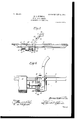
- Figure 1 is an elevation of the wall of a car to which the present invention is at tached.
- Fig. 2 is a top plan view showing the catcher in position to receive a mail-bag.
- Fig. 3 is a view similar to Fig. 2, showing the catcher in position to discharge the bag;
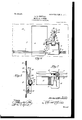
- Fig. 4 is a view showing the catcher in inoperative position.
- Fig. 5 is an end view of Fig. 4.
- Fig. 6 is a detailed section showing the arrangement of the locking-pin.
- Fig. 7 is a detail view showing a top plan view of one of the guide-rails and the adjacent parts.
- FIG. 1 Referring now to the drawings, there is shown one wall 5 of the car having a door 6 therein, and secured to the inner side of the wall there are a pair of horizontally-extending spaced guide-rails 7, which extend across the door 6 and which have longitudinal slots 8 registering vertically and extending be yond the opposite sides of the door. Slidably engaged in these'registering slots there is a bolt 9, which has pivotally engaged therewith between the plates a semicircular plate 10, extending horizontally and having a slot 11 formed therein parallel to its straight edge 12.
- a frame 13 is provided and has angular fingers 14 secured to one of its ends, these fingers being engaged in the slot 1 1 for move ment of the frame longitudinally of the slot, the end of the frame to which the fingers are attached lying against the straight edge 12 of the plate 10.
- the plate lies normally transversely of the guide-rail 7 and extends a considerable distance therebeyond, and it will thus be apparent that the plate may be moved pivotally to cause the frame 13 to lie.
- the frame 13 carries a laterzfily-extending plate 15 at its opposite end to the fingers 14, and this plate projects between the guides 7 for the reception of a bolt 16, engaged in the guides and in the plate, to hold the frame against move ment.
- this frame is movable to lie at opposite sides of the door 6, as will be readily understood.
- the frame includes upwardly-extending members 18 and 19, in which there is journaled a horizontal shaft 20, having a drum 21 mounted thereupon, which carries radial pins 22.
- a helical spring 23 is engaged with one of these pins and is also engaged with a hook 24, secured to the car, this spring being arranged to hold the shaft yieldably against rotation in one direction. It will be understood that the catcher is described with the frame lying at one side of the door 6, and when it is shifted to the opposite side of the door the spring 23 is engaged with another hook 25 and with another one of the pins 22.
- the member 19 of the frame lies adjacent to. the door 6, and in the upper end of this member there is formed a notch 26 for a purpose which will be presently described.
- a plate 27 is carried by the shaft 20 and lies outwardly of the member 19 of the frame, this plate having spaced Wings 28 extending outwardly therefrom. Pivoted between these wings adjacent to one end of the latter there is an arm 29, which extends between the wings and which also extends beyond the ends thereof which lie adjacent to the pivot, and this arm has a jaw 30 at its outer end.
- a cooperating jaw 31 ispivoted to the arm 29 adjacent to the jaw 30, and a spring 32 is connected to this cooperating jaw and to the arm 29 and is arranged to hold the jaw 31 yieldably at the limit of its movement in the direction of the j aw 30.
- a projection 33 is car- IIO ried by the jaw 31, and a latch 34 is pivoted 'to the arm 29, this latch having a notch 35 therein for the reception of the projection 33 to hold the j aw 31 against the action of the spring 32 and in position to receive a mailbag between the jaws.
- the latch '34 extends into position for engagement by a mailbag received between the jaws, and it is so arranged that when thus engaged it is moved to bring its notched portion away from the projection 33, thus releasing the jaw 31.
- the shaft is movable in its bearings to lie with the arm 29 projected through the door 6 and with the jaws 30 and 31 lying outwardly of the car, and the arrangement of the spring 23 is such that when the shaft is in this position the spring is under tension, the tendency of the spring being to move the shaft 20 into position to lie with the arm 29 and the jaws within the car.
- An opening 36 is formed in the plate 27 between the wings 28, and this opening is disposed to receive a pin 37, carried by the arm 29, adjacent to its inner end and extending in the direction of the plate 27.
- An opening 38 is formed in the member 19 of the frame, and when the jaws lie exteriorly of the car and in position to receive the mail-bag the opening 36 registers with the opening 38, and a pin 37 is engaged in the registering openings to hold the shaft against movement under the action of the spring 23.
- the plate 27 is provided with a notch 39 in one of its edges, and this notch is so located that it is registrable with the notch 26 and when thus registered lies with the arm 29 extending upwardly and within the car.
- the arm 29 is movable upon its pivot to enter the registering notches 26 and 39, and thus holds the shaft against movement, the arm then being in inoperative position, as will be readily understood. 7
- a pin 40 may be engaged in the wings 28 to hold the arm 29 against movement into the registering notches.
- the catcher may be disposed to receive mail-bags no matter in which direction the car is moving, and the pins 22 are provided to permit of adjustment of the spring 23 when the frame is shifted to correctly operate the catcher.
- the jaws 30 and 31 are disposed in such position with respect to the arm 29 that they will receive therebetween a mail-bag suspended in the usual manner.
- a catcher comprising spaced guide-rails, a plate pivotally and slidably engaged between the guide-rails, a frame secured to the plate and lying at one side of the guide-rails said frame being movable pivotally with the plate to extend in opposite directions, means for holding the frame and plate against pivotal movement and a catching device carried by the frame.
- a'catcher carried by the shaft and movable into and out of operative position said catcher when in operative position being movable with the shaft into position to receive a mail-bag and into position to discharge the latter said catcher when in inoperative position being arranged to hold the shaft a ainst rotation.
- a device of the class described comprising a frame a shaft revolubly mounted in the frame a catcher carried by the shaft and movable with respect thereto into and out of operative position, said catcher when in operative position being movable with the shaft into position to receive a body and into position to discharge the latter, said catcher being arranged for cooperation with the frame when the catcher is in inoperative position to hold the shaft a ainst rotation.
- a device of the class described comprising a catching device movable into and out of position to receive a body, said device comprising a movable arm means carried by the arm for holding the catcher in position to receive a body said arm being movable by a body received by the catcher to bring the holding means into inoperative position and means for moving the catcher out of position to receive a body when the holding means is moved into inoperative position.
- a device of the class described comprising a frame an arm carried by the frame and having a jaw at one end, a jaw pivoted to the arm for cooperation with the first-named jaw, means for holding the pivoted jaw yieldably at the limit of its movement toward the other jaw and means for holding the pivoted jaw against the action of the yieldable holding means, said second-named holding means including a portion lying in'position for engagement by a body between the jaws for movement of said holding means into inoperative position.
- a catching device comprising pivotallyconnected aws movable toward and away from each other, means for holding the jaws yieldably at the limits of their movements toward each other, a projection carried by one of the jaws and a latch pivoted to the other jaw for movement into and out of engagement with the projection, said latch being arranged when in engagement with the projection to hold the jaws against the action of the yieldable holding means said latch when in operative position lying in position for engagement by a body between the jaws for movement of the latch by said body into inoperative position.
Landscapes
- Engineering & Computer Science (AREA)
- Mechanical Engineering (AREA)
- Supports Or Holders For Household Use (AREA)
Description
N0- 809,187. PATENTED JAN. 2, 1906. H. L. KIMMONS.
MAIL DELIVERER. APPLICATION FILED MAY1,1905.
3 SHBETS-SHEET l.
ahvewEo z Witnesses I PATENTED JAN. 2
H L. KIMMONS! MAIL DELIVERER.
APPLICATION FILED MAY 1, 1905.
3 SHEETS-SHEET 2.
I sluuemfop iii/777 alknnuf- No. 809,187. PATBNTED JAN. 2, 1906. H. L. KIMMONS.
MAIL DBLIVERER.
APPLIOATION FILED MAYl, 1906.
3 SHEETS-SHEET 3.
3 I mentor.
HERBERT L. KIMMONS, OF DECKER, INDIANA.
NIAIL-DELIVERER.
Specification of Letters Patent.
Patented Jan. 2, 1906.
Application filed May 1, 1905. Serial No. 258,242.
To all whom, it may concern.-
7 Be it known that I, HERBERT L. KIM- MONs, a citizen of the United States, residing at Decker, in the county of Knox, State of Indiana, have invented certain new and useful Improvements in Mail-Deliverers; and I do hereby declare the following to be a full, clear, and exact description of the invention, such as will enable others skilled in the art to whichit appertains to make anduse the same.
This invention relates to catchers, and more particularly to mail-bag catchers, and has for its object to provide a catcher including a novel arrangement of parts which will be movable into position to receive and dis charge a mail-bag and which will also be movable to lie in position to catch mail-bags when the direction in which the train is moving is reversed.
Other objects and advantages will be apparent from the following description, and it will be understood that changes in the specific construction shown and described may be made within the scope of the claims and that any suitable materials maybe used without departing from the spirit of the invention.
In the drawings forming a portion of this specification, and in which like numerals of reference indicate similar parts in the several views, Figure 1 is an elevation of the wall of a car to which the present invention is at tached. Fig. 2 is a top plan view showing the catcher in position to receive a mail-bag. Fig. 3 is a view similar to Fig. 2, showing the catcher in position to discharge the bag; Fig. 4 is a view showing the catcher in inoperative position. Fig. 5 is an end view of Fig. 4. Fig. 6 is a detailed section showing the arrangement of the locking-pin. Fig. 7 is a detail view showing a top plan view of one of the guide-rails and the adjacent parts. 1 Referring now to the drawings, there is shown one wall 5 of the car having a door 6 therein, and secured to the inner side of the wall there are a pair of horizontally-extending spaced guide-rails 7, which extend across the door 6 and which have longitudinal slots 8 registering vertically and extending be yond the opposite sides of the door. Slidably engaged in these'registering slots there is a bolt 9, which has pivotally engaged therewith between the plates a semicircular plate 10, extending horizontally and having a slot 11 formed therein parallel to its straight edge 12.
A frame 13 is provided and has angular fingers 14 secured to one of its ends, these fingers being engaged in the slot 1 1 for move ment of the frame longitudinally of the slot, the end of the frame to which the fingers are attached lying against the straight edge 12 of the plate 10. The plate lies normally transversely of the guide-rail 7 and extends a considerable distance therebeyond, and it will thus be apparent that the plate may be moved pivotally to cause the frame 13 to lie.
at op osite sides of the transverselyextend ing p ane of the bolt 9 and against and parallel to the uide-rails 7. The frame 13 carries a laterzfily-extending plate 15 at its opposite end to the fingers 14, and this plate projects between the guides 7 for the reception of a bolt 16, engaged in the guides and in the plate, to hold the frame against move ment. By reason of the pivotal and longitudinal movement of the frame with respect to the guide-rails 7 this frame is movable to lie at opposite sides of the door 6, as will be readily understood.
The frame includes upwardly-extending members 18 and 19, in which there is journaled a horizontal shaft 20, having a drum 21 mounted thereupon, which carries radial pins 22. A helical spring 23 is engaged with one of these pins and is also engaged with a hook 24, secured to the car, this spring being arranged to hold the shaft yieldably against rotation in one direction. It will be understood that the catcher is described with the frame lying at one side of the door 6, and when it is shifted to the opposite side of the door the spring 23 is engaged with another hook 25 and with another one of the pins 22. The member 19 of the frame lies adjacent to. the door 6, and in the upper end of this member there is formed a notch 26 for a purpose which will be presently described.
A plate 27 is carried by the shaft 20 and lies outwardly of the member 19 of the frame, this plate having spaced Wings 28 extending outwardly therefrom. Pivoted between these wings adjacent to one end of the latter there is an arm 29, which extends between the wings and which also extends beyond the ends thereof which lie adjacent to the pivot, and this arm has a jaw 30 at its outer end. A cooperating jaw 31 ispivoted to the arm 29 adjacent to the jaw 30, and a spring 32 is connected to this cooperating jaw and to the arm 29 and is arranged to hold the jaw 31 yieldably at the limit of its movement in the direction of the j aw 30. A projection 33 is car- IIO ried by the jaw 31, and a latch 34 is pivoted 'to the arm 29, this latch having a notch 35 therein for the reception of the projection 33 to hold the j aw 31 against the action of the spring 32 and in position to receive a mailbag between the jaws. The latch '34 extends into position for engagement by a mailbag received between the jaws, and it is so arranged that when thus engaged it is moved to bring its notched portion away from the projection 33, thus releasing the jaw 31.
The shaft is movable in its bearings to lie with the arm 29 projected through the door 6 and with the jaws 30 and 31 lying outwardly of the car, and the arrangement of the spring 23 is such that when the shaft is in this position the spring is under tension, the tendency of the spring being to move the shaft 20 into position to lie with the arm 29 and the jaws within the car. An opening 36 is formed in the plate 27 between the wings 28, and this opening is disposed to receive a pin 37, carried by the arm 29, adjacent to its inner end and extending in the direction of the plate 27. An opening 38 is formed in the member 19 of the frame, and when the jaws lie exteriorly of the car and in position to receive the mail-bag the opening 36 registers with the opening 38, and a pin 37 is engaged in the registering openings to hold the shaft against movement under the action of the spring 23.
The plate 27 is provided with a notch 39 in one of its edges, and this notch is so located that it is registrable with the notch 26 and when thus registered lies with the arm 29 extending upwardly and within the car. The arm 29 is movable upon its pivot to enter the registering notches 26 and 39, and thus holds the shaft against movement, the arm then being in inoperative position, as will be readily understood. 7
A pin 40 may be engaged in the wings 28 to hold the arm 29 against movement into the registering notches.
It will be readily understood that by reason of the fact that the frame is shiftable upon the guides, as mentioned above, the catcher may be disposed to receive mail-bags no matter in which direction the car is moving, and the pins 22 are provided to permit of adjustment of the spring 23 when the frame is shifted to correctly operate the catcher.
The jaws 30 and 31 are disposed in such position with respect to the arm 29 that they will receive therebetween a mail-bag suspended in the usual manner.
What is claimed is 1. The combination with a railway-car of a horizontal guide secured to the car, a frame engaged with the guide and movable longitudinally thereof, a catcher connected with the frame and movable into and out of operative position, means for holding the catcher in inoperative position, means for holding the catcher in operative position, said means being shiftable with res ect to the guide to lie at times with its catciier extending in one direction and at times with its catcher extending in opposite direction.
2. The combination with a railway-car having an opening in the wall thereof, of horizontal guides secured to the car, and a catcher connected with the guides and arranged for movement longitudinally thereof to lie at opposite sides of the opening, said catcher being arranged for movement to lie at times exteriorly of the car and in position to receive a mail-bag and at times interiorly of the car, means for holding the catcher yieldably in this last-named position, means for holding the catcher in position to receive a mail-bag, means for moving the second-named holding means into inoperative position, said thirdnamed means being arranged for operation by the impact of a mail-bag engaged by the catcher said catcher being shiftable pivotally with respect to the guides to extend at times in one direction and at times in the opposite direction and means for holding the catcher against its pivotal movement with respect to the guides.
3. A catcher comprising spaced guide-rails, a plate pivotally and slidably engaged between the guide-rails, a frame secured to the plate and lying at one side of the guide-rails said frame being movable pivotally with the plate to extend in opposite directions, means for holding the frame and plate against pivotal movement and a catching device carried by the frame.
4. In a device of the class described the combination with a frame of a shaft revolubly mounted in a frame, a'catcher carried by the shaft and movable into and out of operative position said catcher when in operative position being movable with the shaft into position to receive a mail-bag and into position to discharge the latter said catcher when in inoperative position being arranged to hold the shaft a ainst rotation.
5. A device of the class described comprising a frame a shaft revolubly mounted in the frame a catcher carried by the shaft and movable with respect thereto into and out of operative position, said catcher when in operative position being movable with the shaft into position to receive a body and into position to discharge the latter, said catcher being arranged for cooperation with the frame when the catcher is in inoperative position to hold the shaft a ainst rotation.
6. A device of the class described comprising a catching device movable into and out of position to receive a body, said device comprising a movable arm means carried by the arm for holding the catcher in position to receive a body said arm being movable by a body received by the catcher to bring the holding means into inoperative position and means for moving the catcher out of position to receive a body when the holding means is moved into inoperative position.
7. A device of the class described comprising a frame an arm carried by the frame and having a jaw at one end, a jaw pivoted to the arm for cooperation with the first-named jaw, means for holding the pivoted jaw yieldably at the limit of its movement toward the other jaw and means for holding the pivoted jaw against the action of the yieldable holding means, said second-named holding means including a portion lying in'position for engagement by a body between the jaws for movement of said holding means into inoperative position.
8. A catching device comprising pivotallyconnected aws movable toward and away from each other, means for holding the jaws yieldably at the limits of their movements toward each other, a projection carried by one of the jaws and a latch pivoted to the other jaw for movement into and out of engagement with the projection, said latch being arranged when in engagement with the projection to hold the jaws against the action of the yieldable holding means said latch when in operative position lying in position for engagement by a body between the jaws for movement of the latch by said body into inoperative position.
In testimony whereof I afiix my signature in presence of two witnesses.
HERBERT L. KIMMONS.
Witnesses EMERY F. SMALL, J. S. TODD.
Priority Applications (1)
| Application Number | Priority Date | Filing Date | Title |
|---|---|---|---|
| US25824205A US809187A (en) | 1905-05-01 | 1905-05-01 | Mail-deliverer. |
Applications Claiming Priority (1)
| Application Number | Priority Date | Filing Date | Title |
|---|---|---|---|
| US25824205A US809187A (en) | 1905-05-01 | 1905-05-01 | Mail-deliverer. |
Publications (1)
| Publication Number | Publication Date |
|---|---|
| US809187A true US809187A (en) | 1906-01-02 |
Family
ID=2877668
Family Applications (1)
| Application Number | Title | Priority Date | Filing Date |
|---|---|---|---|
| US25824205A Expired - Lifetime US809187A (en) | 1905-05-01 | 1905-05-01 | Mail-deliverer. |
Country Status (1)
| Country | Link |
|---|---|
| US (1) | US809187A (en) |
-
1905
- 1905-05-01 US US25824205A patent/US809187A/en not_active Expired - Lifetime
Similar Documents
| Publication | Publication Date | Title |
|---|---|---|
| US809187A (en) | Mail-deliverer. | |
| US829213A (en) | Mail-bag-delivering device. | |
| US847960A (en) | Mail-bag exchanger. | |
| US685324A (en) | Device for receiving and delivering mail-bags. | |
| US991838A (en) | Mail-bag catcher. | |
| US805278A (en) | Mail-crane. | |
| US769268A (en) | Mail-bag catching and delivering device. | |
| US298216A (en) | Mail-bag catcher | |
| US1051676A (en) | Mail-bag catcher and deliverer. | |
| US1372602A (en) | Mail-receiving device | |
| US824440A (en) | Mail-catching device. | |
| US441986A (en) | Signors of one-half to charles e | |
| US800135A (en) | Mail-bag catcher. | |
| US814630A (en) | Mail-bag catcher. | |
| US1043892A (en) | Mail-bag handler. | |
| US1075921A (en) | Automatic mail-crane. | |
| US787651A (en) | Mail-bag catcher. | |
| US1050106A (en) | Mail-collecting device. | |
| US1113595A (en) | Mail-bag catching and delivering apparatus. | |
| US1011709A (en) | Mail-bag catcher and deliverer. | |
| US641622A (en) | Mail-bag catcher and deliverer. | |
| US1020201A (en) | Mail receiving and delivering apparatus. | |
| US979723A (en) | Mail-bag catching and delivering apparatus. | |
| US804035A (en) | Mail-bag catcher. | |
| US1381414A (en) | Railway mail-dslivebing apparatus |