US8091829B2 - Lifting structure for aircraft - Google Patents
Lifting structure for aircraft Download PDFInfo
- Publication number
- US8091829B2 US8091829B2 US12/073,770 US7377008A US8091829B2 US 8091829 B2 US8091829 B2 US 8091829B2 US 7377008 A US7377008 A US 7377008A US 8091829 B2 US8091829 B2 US 8091829B2
- Authority
- US
- United States
- Prior art keywords
- aircraft
- central rib
- lifting structure
- horizontal stabilizer
- boxes
- Prior art date
- Legal status (The legal status is an assumption and is not a legal conclusion. Google has not performed a legal analysis and makes no representation as to the accuracy of the status listed.)
- Expired - Fee Related, expires
Links
- 239000003381 stabilizer Substances 0.000 claims abstract description 18
- 239000000463 material Substances 0.000 claims description 8
- OKTJSMMVPCPJKN-UHFFFAOYSA-N Carbon Chemical compound [C] OKTJSMMVPCPJKN-UHFFFAOYSA-N 0.000 claims description 6
- 229910052799 carbon Inorganic materials 0.000 claims description 6
- 239000000835 fiber Substances 0.000 claims description 6
- 238000000034 method Methods 0.000 abstract description 4
- 229920000049 Carbon (fiber) Polymers 0.000 abstract 1
- 239000004917 carbon fiber Substances 0.000 abstract 1
- VNWKTOKETHGBQD-UHFFFAOYSA-N methane Chemical compound C VNWKTOKETHGBQD-UHFFFAOYSA-N 0.000 abstract 1
- 239000013585 weight reducing agent Substances 0.000 abstract 1
- 210000003414 extremity Anatomy 0.000 description 9
- 239000002131 composite material Substances 0.000 description 4
- 230000007704 transition Effects 0.000 description 3
- 238000010586 diagram Methods 0.000 description 2
- 238000005553 drilling Methods 0.000 description 2
- 238000003780 insertion Methods 0.000 description 2
- 230000037431 insertion Effects 0.000 description 2
- RTAQQCXQSZGOHL-UHFFFAOYSA-N Titanium Chemical compound [Ti] RTAQQCXQSZGOHL-UHFFFAOYSA-N 0.000 description 1
- 238000013461 design Methods 0.000 description 1
- 230000000694 effects Effects 0.000 description 1
- 238000010348 incorporation Methods 0.000 description 1
- 238000007689 inspection Methods 0.000 description 1
- 238000012423 maintenance Methods 0.000 description 1
- 239000007769 metal material Substances 0.000 description 1
- 239000000565 sealant Substances 0.000 description 1
- 238000007789 sealing Methods 0.000 description 1
- 239000007787 solid Substances 0.000 description 1
- 239000003351 stiffener Substances 0.000 description 1
- 230000001502 supplementing effect Effects 0.000 description 1
- 229910052719 titanium Inorganic materials 0.000 description 1
- 239000010936 titanium Substances 0.000 description 1
- 210000001364 upper extremity Anatomy 0.000 description 1
Images


Classifications
-
- B—PERFORMING OPERATIONS; TRANSPORTING
- B64—AIRCRAFT; AVIATION; COSMONAUTICS
- B64C—AEROPLANES; HELICOPTERS
- B64C5/00—Stabilising surfaces
- B64C5/02—Tailplanes
-
- B—PERFORMING OPERATIONS; TRANSPORTING
- B64—AIRCRAFT; AVIATION; COSMONAUTICS
- B64C—AEROPLANES; HELICOPTERS
- B64C1/00—Fuselages; Constructional features common to fuselages, wings, stabilising surfaces or the like
- B64C1/26—Attaching the wing or tail units or stabilising surfaces
Definitions
- the present invention refers to a lifting structure for aircraft that is used essentially as a horizontal stabilizer situated in the rear area of the aircraft.
- the stabilizer consists in principal of two symmetrical, lateral boxes that remain solid due to certain characteristic joining methods that enable us to use a single, lighter material, such as carbon fibre.
- the structure of the invention has a characteristic design that enables us to achieve a higher level of performance and effectiveness.
- lateral boxes for lifting structures for aircraft consists of a central metallic box that provides wings for inserting and riveting the lateral boxes. These in all cases have a flat structure, normally sloping upwards towards their free extremities.
- Another known solution is a joint that incorporates upper or lower formers in titanium, with a central ribbing made of carbon fibre.
- a third solution consists of a double shear joint.
- This consists of upper and lower partial formers installed in the interior of the box, with exterior plates and central ribbing in composite material, creating a double shear joint.
- Another known solution is a joint that includes a former in several sections.
- the lifting structures for aircraft that constitutes the object of the invention is characterised by a single, central, integral component which acts as the nexus for joining a number of symmetrical lateral boxes to form a horizontal stabilizer.
- the joint between the integral component and the side boxes is complemented by some strong rivets that are inserted from inside, into aligned holes made previously in superimposed laminated sections belonging to the three parts of the structure previously mentioned.
- the central piece consists of a configuration in the form of a double “T”, the extremities of which incorporate a number of flaps, at the rear and front, positioned perpendicularly at the extremities from the core of this central piece, which make their union to the rear and front lifting possible.
- the lifting structure assembly has a characteristic, curved configuration when seen from the front. This is such that in the areas where they meet the integral central component, the lateral boxes have extremities that make further contact with the internal faces of the profile's wings in the form of a double “T”, incorporating the rivets precisely in these contact areas.
- FIG. 1 Shows a view of the structure for aircraft from the front, the structure being the object of the invention. Its application is essentially as a horizontal stabiliser.
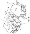
- FIG. 2 Shows a view in perspective of a part of the lifting structure of the invention.
- the view shows an arrangement for joining the two lateral boxes of the stabiliser by means of a characteristic single central piece, in the manner of an integral rib.
- FIG. 3 Shows a view of the mounting of the integral rib onto the lateral boxes.
- the structure for aircraft serves essentially as a horizontal stabilizer and consists of two symmetrical lateral boxes ( 1 ) that are joined together by a single, central piece ( 2 ) constituting a rib in the form of a double “T”, in such a way that the extremities ( 3 ) of the boxes ( 1 ) overlap the internal faces of the wings ( 4 ) of the rib ( 2 ), close to the core ( 5 ) of the central piece ( 2 ).
- the central rib ( 2 ) incorporates a number of flaps ( 7 ) for joining to a number of supports, at the front and at the rear (not shown in the diagrams).
- the flaps are situated perpendicularly at the extremities of the core ( 5 ) of the central rib ( 2 ) forming an integral part of it.
- central rib ( 2 ) gradually increases in height from the rear extremity to the front extremity, this variation in height being complemented by the extreme portions ( 3 ) of the lateral boxes ( 1 ).
- the horizontal stabilizer consists of symmetrical boxes ( 1 ) that have a characteristic arch that increases in height as it goes outwards, in such a way that in this case the sections at the extremities ( 3 ) that overlap with the wings ( 4 ) of the central rib ( 2 ) are prepared in advance so as to be fitted to the wings ( 4 ) of the central rib ( 2 ).
- This preparation consists simply of flattening these end sections ( 3 ) so that they sit perfectly on the flat wings ( 4 ) of the central rib ( 2 ), thereby creating a flat transition.
- This transition between the two boxes ( 1 ) is made on a surface that is not wet, and does not affect the aerodynamics of the aircraft.
- the rib wing interface angle must be sufficient to ensure union with the rib and ensure that the work of sealing and supplementing can be carried out without pulling on the sealant used. In the front area, this angle must be such that it is possible to install the front part correctly.
- the central rib will vary in thickness towards the exterior, taking into account the rows of rivets with the skin.
- the front opening must be sufficiently large to allow access and the insertion of the rivets in the aligned holes, deforming the rivet collars from outside.
- the rib can incorporate the rear and front section stiffeners and angle pieces.
- the assembly system must be compatible with a box assembly system “to aerodynamic tolerances” that locally (in the area of the joint) ensures exterior tolerances that are compatible with the rib. This can be achieved either by means of adding material to the assembly, having designed the sections to be compatible with it, or applying extra material to the support elements of the skin which can be removed if necessary.
Landscapes
- Engineering & Computer Science (AREA)
- Aviation & Aerospace Engineering (AREA)
- Mechanical Engineering (AREA)
- Connection Of Plates (AREA)
- Body Structure For Vehicles (AREA)
Abstract
Description
-
- Joining the materials involved (carbon fibre), increasing the percentage of composite material as much as possible
- Improving the processes of drilling and riveting by eliminating different materials, achieving improvements in tolerances and saving time making holes, as well as reducing non-conformities.
- Significant improvement for the client in terms of inspection and maintenance, by not incorporating metallic materials.
Claims (9)
Applications Claiming Priority (3)
| Application Number | Priority Date | Filing Date | Title |
|---|---|---|---|
| ES200703393A ES2351823B1 (en) | 2007-12-21 | 2007-12-21 | SUSTAINING STRUCTURE FOR AIRCRAFT. |
| ESP200703393 | 2007-12-21 | ||
| ES200703393 | 2007-12-21 |
Publications (2)
| Publication Number | Publication Date |
|---|---|
| US20090159742A1 US20090159742A1 (en) | 2009-06-25 |
| US8091829B2 true US8091829B2 (en) | 2012-01-10 |
Family
ID=40787442
Family Applications (1)
| Application Number | Title | Priority Date | Filing Date |
|---|---|---|---|
| US12/073,770 Expired - Fee Related US8091829B2 (en) | 2007-12-21 | 2008-03-10 | Lifting structure for aircraft |
Country Status (2)
| Country | Link |
|---|---|
| US (1) | US8091829B2 (en) |
| ES (1) | ES2351823B1 (en) |
Cited By (1)
| Publication number | Priority date | Publication date | Assignee | Title |
|---|---|---|---|---|
| US20110174928A1 (en) * | 2010-01-15 | 2011-07-21 | Airbus Operations S.L. | Joining arrangement for the lateral boxes of a horizontal tail stabiliser with a tubular central box and manufacturing method for said box |
Families Citing this family (10)
| Publication number | Priority date | Publication date | Assignee | Title |
|---|---|---|---|---|
| ES2391102B1 (en) * | 2010-01-14 | 2013-10-09 | Airbus Operations, S.L. | PROVISION OF THE UNION OF TWO DRAWERS OF MATERIAL COMPOSED WITH AN INTERMEDIATE PART AND MANUFACTURING PROCEDURE OF SUCH INTERMEDIATE PIECE |
| ES2372849B1 (en) * | 2010-03-25 | 2012-12-13 | Airbus Operations, S.L. | STRUCTURE OF UNION OF TORSION DRAWERS IN AN AIRCRAFT THROUGH A TRIFORM HARDWARE OF NON-METAL COMPOSITE MATERIALS. |
| CN104010940B (en) * | 2011-11-30 | 2016-11-16 | 空中客车简易股份公司 | The component with case structure for aircraft wing |
| RU2481243C1 (en) * | 2012-01-31 | 2013-05-10 | Закрытое акционерное общество "Гражданские самолеты Сухого" | Aircraft wing and outer wing joint assembly |
| GB201217801D0 (en) * | 2012-10-05 | 2012-11-14 | Airbus Operations Ltd | An aircraft structure |
| CN103434636B (en) * | 2013-09-03 | 2016-08-17 | 中国商用飞机有限责任公司 | Fuselage butt joint structure for connecting aircraft vertical tails and aircraft comprising fuselage butt joint structure |
| CN104494808B (en) * | 2014-12-23 | 2017-01-04 | 无锡透平叶片有限公司 | A kind of structure being prone to the shaping of titanium alloy forging height muscle |
| EP3040268A1 (en) * | 2014-12-30 | 2016-07-06 | Airbus Operations, S.L. | Stringer stiffened aircraft composite structures |
| FR3091259A1 (en) * | 2018-12-26 | 2020-07-03 | Airbus Operations | AIRCRAFT SAIL COMPRISING TWO FIXED WINGS ONE OVER THE OTHER |
| EP4089009A1 (en) * | 2021-05-14 | 2022-11-16 | Airbus Operations, S.L.U. | A method for assembling an aircraft lifting surface |
Citations (10)
| Publication number | Priority date | Publication date | Assignee | Title |
|---|---|---|---|---|
| FR966757A (en) | 1939-11-29 | 1950-10-18 | Improvements in propulsion and aircraft construction | |
| US2567124A (en) * | 1946-05-10 | 1951-09-04 | Curtiss Wright Corp | Airfoil construction |
| US2838260A (en) | 1953-08-06 | 1958-06-10 | Northrop Aircraft Inc | Wing mount with floating center section |
| US4481703A (en) * | 1980-02-25 | 1984-11-13 | Rockwell International Corporation | Method of making rib structures for an airfoil |
| US4662587A (en) * | 1981-09-30 | 1987-05-05 | The Boeing Company | Composite for aircraft wing and method of making |
| US5288355A (en) * | 1989-11-06 | 1994-02-22 | The B.F. Goodrich Company | Structural airfoil having integral expulsive system |
| US6386481B1 (en) * | 2001-01-08 | 2002-05-14 | Patria Finavicomp Oy | Arrangement for fastening stringers to aircraft wing ribs |
| US20040011927A1 (en) * | 2002-07-19 | 2004-01-22 | Christman David B. | Apparatuses and methods for joining structural members, such as composite structural members |
| US6786452B2 (en) * | 2002-06-24 | 2004-09-07 | Honda Giken Kogyo Kabushiki Kaisha | Wing structure of airplane |
| WO2008152248A2 (en) | 2007-05-23 | 2008-12-18 | Airbus France | Aircraft structural element located at the interface between a wing and the fuselage |
-
2007
- 2007-12-21 ES ES200703393A patent/ES2351823B1/en not_active Expired - Fee Related
-
2008
- 2008-03-10 US US12/073,770 patent/US8091829B2/en not_active Expired - Fee Related
Patent Citations (11)
| Publication number | Priority date | Publication date | Assignee | Title |
|---|---|---|---|---|
| FR966757A (en) | 1939-11-29 | 1950-10-18 | Improvements in propulsion and aircraft construction | |
| US2567124A (en) * | 1946-05-10 | 1951-09-04 | Curtiss Wright Corp | Airfoil construction |
| US2838260A (en) | 1953-08-06 | 1958-06-10 | Northrop Aircraft Inc | Wing mount with floating center section |
| US4481703A (en) * | 1980-02-25 | 1984-11-13 | Rockwell International Corporation | Method of making rib structures for an airfoil |
| US4662587A (en) * | 1981-09-30 | 1987-05-05 | The Boeing Company | Composite for aircraft wing and method of making |
| US5288355A (en) * | 1989-11-06 | 1994-02-22 | The B.F. Goodrich Company | Structural airfoil having integral expulsive system |
| US6386481B1 (en) * | 2001-01-08 | 2002-05-14 | Patria Finavicomp Oy | Arrangement for fastening stringers to aircraft wing ribs |
| US6786452B2 (en) * | 2002-06-24 | 2004-09-07 | Honda Giken Kogyo Kabushiki Kaisha | Wing structure of airplane |
| US20040011927A1 (en) * | 2002-07-19 | 2004-01-22 | Christman David B. | Apparatuses and methods for joining structural members, such as composite structural members |
| WO2008152248A2 (en) | 2007-05-23 | 2008-12-18 | Airbus France | Aircraft structural element located at the interface between a wing and the fuselage |
| US20100170986A1 (en) | 2007-05-23 | 2010-07-08 | Airbus Operations | Aircraft structural element located at the interface between a wing and the fuselage |
Non-Patent Citations (1)
| Title |
|---|
| M. C. Niu, "Airframe Structural Design," Conmilit Press Ltd., Hong Kong, pp. 282 and 283, Feb. 2002. |
Cited By (2)
| Publication number | Priority date | Publication date | Assignee | Title |
|---|---|---|---|---|
| US20110174928A1 (en) * | 2010-01-15 | 2011-07-21 | Airbus Operations S.L. | Joining arrangement for the lateral boxes of a horizontal tail stabiliser with a tubular central box and manufacturing method for said box |
| US8720824B2 (en) * | 2010-01-15 | 2014-05-13 | Airbus Operations S.L. | Joining arrangement for the lateral boxes of a horizontal tail stabiliser with a tubular central box and manufacturing method for said box |
Also Published As
| Publication number | Publication date |
|---|---|
| US20090159742A1 (en) | 2009-06-25 |
| ES2351823B1 (en) | 2011-12-05 |
| ES2351823A1 (en) | 2011-02-11 |
Similar Documents
| Publication | Publication Date | Title |
|---|---|---|
| US8091829B2 (en) | Lifting structure for aircraft | |
| CN101432189B (en) | Aircraft fuselage structure and manufacturing method thereof | |
| EP2311728A2 (en) | Structure of an aircraft aerofoil | |
| CN110573421B (en) | Assembly for an aircraft comprising a primary structure of an attachment pylon attached to a wing box using bolted connections | |
| US10486791B2 (en) | Aerofoil structure components | |
| CN101410292B (en) | Aircraft component, aircraft structure and method for manufacturing the component and structure | |
| CN101578220B (en) | Section of aircraft fuselage and aircraft including one such section | |
| US7641147B2 (en) | Airplane wing, method for manufacturing an airplane wing and use of a welding process for welding a wing spar | |
| US2211089A (en) | Wing and fuselage construction | |
| US9957036B2 (en) | Aircraft structure | |
| US8746621B2 (en) | Connector for stiffening frames between an aircraft fuselage and a wing box | |
| US20120234978A1 (en) | Load transfer devices at a stringer run-out | |
| CN107416183A (en) | A kind of spar attachment structure of aircraft wing | |
| CN110603192B (en) | Aircraft Wing-to-Fuselage Interface Allowing Position Adjustment | |
| US9102394B2 (en) | Flow body with a base body and a leading edge | |
| US20180155006A1 (en) | Aircraft stabilizer leading edge integration with torsion box and fuselage | |
| CN105644765B (en) | Aircraft fuselage frame | |
| EP2886449A1 (en) | Leading edge for an aircraft lifting surface | |
| US9868539B2 (en) | Aircraft engine pylon to wing mounting assembly | |
| ES2953735T3 (en) | Trailing edge for a composite multi-spar integrated lifting surface and manufacturing method of said trailing edge | |
| US2451454A (en) | Method of fabricating airfoils | |
| JP2009502642A (en) | Improved aircraft engine primary strut structure | |
| US8348197B2 (en) | Integration system for lifting surface lateral parts in an aircraft | |
| CN102849218A (en) | Mounting beam for auxiliary power unit of aircraft | |
| EP3998192B1 (en) | Wing spar structure |
Legal Events
| Date | Code | Title | Description |
|---|---|---|---|
| AS | Assignment |
Owner name: AIRBUS ESPANA, S.L.,SPAIN Free format text: ASSIGNMENT OF ASSIGNORS INTEREST;ASSIGNORS:RAMIREZ BLANCO, GONZALO;BARROSO VLOEDGRAVEN, DANIEL;LOZANO GARCIA, JOSE LOUIS;AND OTHERS;REEL/FRAME:021146/0367 Effective date: 20080508 Owner name: AIRBUS ESPANA, S.L., SPAIN Free format text: ASSIGNMENT OF ASSIGNORS INTEREST;ASSIGNORS:RAMIREZ BLANCO, GONZALO;BARROSO VLOEDGRAVEN, DANIEL;LOZANO GARCIA, JOSE LOUIS;AND OTHERS;REEL/FRAME:021146/0367 Effective date: 20080508 |
|
| AS | Assignment |
Owner name: AIRBUS OPERATIONS, S.L., SPAIN Free format text: CHANGE OF NAME;ASSIGNOR:AIRBUS ESPANA, S.L.;REEL/FRAME:023861/0978 Effective date: 20090506 Owner name: AIRBUS OPERATIONS, S.L.,SPAIN Free format text: CHANGE OF NAME;ASSIGNOR:AIRBUS ESPANA, S.L.;REEL/FRAME:023861/0978 Effective date: 20090506 |
|
| ZAAA | Notice of allowance and fees due |
Free format text: ORIGINAL CODE: NOA |
|
| ZAAB | Notice of allowance mailed |
Free format text: ORIGINAL CODE: MN/=. |
|
| STCF | Information on status: patent grant |
Free format text: PATENTED CASE |
|
| FEPP | Fee payment procedure |
Free format text: PAYOR NUMBER ASSIGNED (ORIGINAL EVENT CODE: ASPN); ENTITY STATUS OF PATENT OWNER: LARGE ENTITY |
|
| FPAY | Fee payment |
Year of fee payment: 4 |
|
| MAFP | Maintenance fee payment |
Free format text: PAYMENT OF MAINTENANCE FEE, 8TH YEAR, LARGE ENTITY (ORIGINAL EVENT CODE: M1552); ENTITY STATUS OF PATENT OWNER: LARGE ENTITY Year of fee payment: 8 |
|
| FEPP | Fee payment procedure |
Free format text: MAINTENANCE FEE REMINDER MAILED (ORIGINAL EVENT CODE: REM.); ENTITY STATUS OF PATENT OWNER: LARGE ENTITY |
|
| LAPS | Lapse for failure to pay maintenance fees |
Free format text: PATENT EXPIRED FOR FAILURE TO PAY MAINTENANCE FEES (ORIGINAL EVENT CODE: EXP.); ENTITY STATUS OF PATENT OWNER: LARGE ENTITY |
|
| STCH | Information on status: patent discontinuation |
Free format text: PATENT EXPIRED DUE TO NONPAYMENT OF MAINTENANCE FEES UNDER 37 CFR 1.362 |
|
| FP | Lapsed due to failure to pay maintenance fee |
Effective date: 20240110 |