US809165A - Brake mechanism. - Google Patents
Brake mechanism. Download PDFInfo
- Publication number
- US809165A US809165A US26732605A US1905267326A US809165A US 809165 A US809165 A US 809165A US 26732605 A US26732605 A US 26732605A US 1905267326 A US1905267326 A US 1905267326A US 809165 A US809165 A US 809165A
- Authority
- US
- United States
- Prior art keywords
- lever
- link
- arm
- bar
- rounded
- Prior art date
- Legal status (The legal status is an assumption and is not a legal conclusion. Google has not performed a legal analysis and makes no representation as to the accuracy of the status listed.)
- Expired - Lifetime
Links
- 230000007246 mechanism Effects 0.000 title description 10
- 238000013459 approach Methods 0.000 description 1
- 230000007423 decrease Effects 0.000 description 1
Images
Classifications
-
- B—PERFORMING OPERATIONS; TRANSPORTING
- B60—VEHICLES IN GENERAL
- B60T—VEHICLE BRAKE CONTROL SYSTEMS OR PARTS THEREOF; BRAKE CONTROL SYSTEMS OR PARTS THEREOF, IN GENERAL; ARRANGEMENT OF BRAKING ELEMENTS ON VEHICLES IN GENERAL; PORTABLE DEVICES FOR PREVENTING UNWANTED MOVEMENT OF VEHICLES; VEHICLE MODIFICATIONS TO FACILITATE COOLING OF BRAKES
- B60T11/00—Transmitting braking action from initiating means to ultimate brake actuator without power assistance or drive or where such assistance or drive is irrelevant
- B60T11/04—Transmitting braking action from initiating means to ultimate brake actuator without power assistance or drive or where such assistance or drive is irrelevant transmitting mechanically
- B60T11/08—Transmitting braking action from initiating means to ultimate brake actuator without power assistance or drive or where such assistance or drive is irrelevant transmitting mechanically providing variable leverage
-
- Y—GENERAL TAGGING OF NEW TECHNOLOGICAL DEVELOPMENTS; GENERAL TAGGING OF CROSS-SECTIONAL TECHNOLOGIES SPANNING OVER SEVERAL SECTIONS OF THE IPC; TECHNICAL SUBJECTS COVERED BY FORMER USPC CROSS-REFERENCE ART COLLECTIONS [XRACs] AND DIGESTS
- Y10—TECHNICAL SUBJECTS COVERED BY FORMER USPC
- Y10T—TECHNICAL SUBJECTS COVERED BY FORMER US CLASSIFICATION
- Y10T74/00—Machine element or mechanism
- Y10T74/20—Control lever and linkage systems
- Y10T74/20558—Variable output force
- Y10T74/2057—Variable input leverage
Definitions
- Patented J' an. 2, 1906.
- This invention relates to power-levers, and especially to those designed for operating braking mechanisms of vehicles, although it is readily susceptible of other uses.
- the invention provides simple and effective means whicli is strong and durable and whereby the initial movement of the brakeshoe against the wheel or the initial movement of any other mechanism operated by the lever is faster with a constant and equal movement of the lever than the after movement when the brake-shoe or other element is thrown into service.
- 3 designates the side of a wagon-box or other part of a vehicle to which is attached a ratchet-bar 4 by bolts 5, the ratchet-bar being curved, so as to extend one end 6 to a point under teeth 7 oi' the bar.
- One en d of a hand-lever 8 is formed with an enlar ed and rounded end 9, from which projects ,laterally a short arm 10, at the end of which on pivot-pin 11 the lever is fulerumed to the end 6 of the ratchet-bar 4.
- a manually-operable pawl 7a is provided on lever 8 for cooperation with teeth 7 of ratchetbar 4 for the purpose of holding the lever at any point desired.
- a link 12 is disposed adjacent to lever 8 and is pivoted at its upper end to the upper part of ratchet-bar 4 at 13, and at the lower end of link 12 is pivotally connected a rod or other suitable means 14, which is attached to and operates the brake or other mechanism.
- connecting-point 16 of straps 17 is substantially above pivot -point 11.
- point 16 moves in a circular path with point 1 1 as a center, and thus moves straps 17 link 12, and connecting means 14 to operate a brake or to attain other desired results.
- point 16 thus moves it approaches a position in line between points 11 of the lever and 18 of the link and that therefore the relative movement of the link with respect to that of the free end of the lever decreases as the movement progresses and that the leverage thus increases.
- the ratginand-pawl mechanism 7 and 7a serves to hold the lever in advanced position in an obvious manner.
- a lever having a laterally-projecting arm near its end, and on which it is fulcrumed, and a rounded end continuing to the arm, in combination with a pivoted link, and straps connecting said arm and link, wherebyvsaid rounded arm end is held in contact with said link.
- a lever having a laterally-projecting arm near its end and on which it is fulcrumed and a rounded end continuing to the arm, in combination with a pivoted link and IOO IIO
- Mechanism of the character described comprising a ratchet-bar having one end curved under itself, a lever terminating in a laterally-projecting arm and a rounded end continuing to the arm and ulcrurned at the end of the arm to the lower partof said ratchet-bar, a link pivoted to the upper part of said ratchet-bar and having on its side adjacent to the lever a groove in which said rounded lever end is operable, straps connecting said lever and link, means at the lower end of said link whereby the mechanism to be operated is moved, and a pawl on said lever and cooperating with said ratchet-bar.
Landscapes
- Engineering & Computer Science (AREA)
- Transportation (AREA)
- Mechanical Engineering (AREA)
- Braking Elements And Transmission Devices (AREA)
Description
PATENTED JAN. 2, 1906.
H. S. BEENEY.
BRAKE MECHANISM.
APPLIOATmN FILED JUNE 28,1905.
UNITED j STATES PATENT OFFIOE.
Specification of Letters Patent.
Patented J' an. 2, 1906.
Appiiaiion tied rune 28,1905. sel-iai No. 267,326.
To @ZZ whom t may concern:
Be it known that I, HENRY S. BEENEY, a
citizen of the United States, residing at Eliza,
Y following is a specification, reference being had therein to the accompanying drawings.
This invention relates to power-levers, and especially to those designed for operating braking mechanisms of vehicles, although it is readily susceptible of other uses.
The invention provides simple and effective means whicli is strong and durable and whereby the initial movement of the brakeshoe against the wheel or the initial movement of any other mechanism operated by the lever is faster with a constant and equal movement of the lever than the after movement when the brake-shoe or other element is thrown into service.
Novel details will be apparent from the detail description hereinafter, when read in connec-tion with the accompanying drawings, forming part hereof, and wherein a preferable embodiment of the invention is disclosed for purposes of illustration.
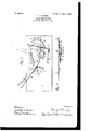
In the drawings like reference characters refer to corresponding parts in both the views,v of which- Figure 1 is a side view of the brakelever and associated mechanism, the full lines showing the position of the lever when the brake is off and the dotted lines its position when the brake is on and Fig. 2 is a sectional view on the line .e e', Fig. 1. Y y
Referring more particularly to the drawings, 3 designates the side of a wagon-box or other part of a vehicle to which is attached a ratchet-bar 4 by bolts 5, the ratchet-bar being curved, so as to extend one end 6 to a point under teeth 7 oi' the bar.
One en d of a hand-lever 8 is formed with an enlar ed and rounded end 9, from which projects ,laterally a short arm 10, at the end of which on pivot-pin 11 the lever is fulerumed to the end 6 of the ratchet-bar 4. A manually-operable pawl 7a is provided on lever 8 for cooperation with teeth 7 of ratchetbar 4 for the purpose of holding the lever at any point desired. A link 12 is disposed adjacent to lever 8 and is pivoted at its upper end to the upper part of ratchet-bar 4 at 13, and at the lower end of link 12 is pivotally connected a rod or other suitable means 14, which is attached to and operates the brake or other mechanism. In the side of link 12 adjacent tolever 8 is sunk a groove 15, in and against the bottom surface of which the rounded end 9 of the lever seats and is operable. At a point 16 of the lever 8 about midway between the pivot in its arm 10 and its opposite edge are pivotally-connected straps 17, which are pivotally connected at 18 to link 12 about midway of its ends, one of the straps being disposed on each side of the lever and link.
When the brake or other mechanism to be operated is at rest or in ineffective position, connecting-point 16 of straps 17 is substantially above pivot -point 11. Upon movement of the lever in direction of the arrow, Fig. 1, point 16 moves in a circular path with point 1 1 as a center, and thus moves straps 17 link 12, and connecting means 14 to operate a brake or to attain other desired results. It will be seen that as point 16 thus moves it approaches a position in line between points 11 of the lever and 18 of the link and that therefore the relative movement of the link with respect to that of the free end of the lever decreases as the movement progresses and that the leverage thus increases. The ratchetand-pawl mechanism 7 and 7a serves to hold the lever in advanced position in an obvious manner. That part of the rounded end 9 ofthe lever which seats in groove 15 contacts with the correspondingly rounded bottom surface of said groove, and as the lever advances the operation of the lever end thereagainst causes the link to move. It will thus be seen that on advance of the lever movement is given to the link by this means just described, as well as by the straps, and that the straps serve to draw the link in the opposite direction on reversal of movement of the lever, and thus let off the mechanism operated by connecting means 14.
Having thus described my invention, what I claim as new, and desire to secure by Letters Patent, is-
1. A lever having a laterally-projecting arm near its end, and on which it is fulcrumed, and a rounded end continuing to the arm, in combination with a pivoted link, and straps connecting said arm and link, wherebyvsaid rounded arm end is held in contact with said link.
2. A lever having a laterally-projecting arm near its end and on which it is fulcrumed and a rounded end continuing to the arm, in combination with a pivoted link and IOO IIO
means whereby said link is held in contact with said lever, said link having in its side adjacent to the lever a groove in which said rounded lever end is operable.
3. Mechanism of the character described, comprising a ratchet-bar having one end curved under itself, a lever terminating in a laterally-projecting arm and a rounded end continuing to the arm and ulcrurned at the end of the arm to the lower partof said ratchet-bar, a link pivoted to the upper part of said ratchet-bar and having on its side adjacent to the lever a groove in which said rounded lever end is operable, straps connecting said lever and link, means at the lower end of said link whereby the mechanism to be operated is moved, and a pawl on said lever and cooperating with said ratchet-bar.
In testimony whereof I afx my signature in presence of two witnesses.
HENRY S. BEENEY. Witnesses:
WILLIAM H. BISHOP, ADNA MILLER.
Priority Applications (1)
| Application Number | Priority Date | Filing Date | Title |
|---|---|---|---|
| US26732605A US809165A (en) | 1905-06-28 | 1905-06-28 | Brake mechanism. |
Applications Claiming Priority (1)
| Application Number | Priority Date | Filing Date | Title |
|---|---|---|---|
| US26732605A US809165A (en) | 1905-06-28 | 1905-06-28 | Brake mechanism. |
Publications (1)
| Publication Number | Publication Date |
|---|---|
| US809165A true US809165A (en) | 1906-01-02 |
Family
ID=2877646
Family Applications (1)
| Application Number | Title | Priority Date | Filing Date |
|---|---|---|---|
| US26732605A Expired - Lifetime US809165A (en) | 1905-06-28 | 1905-06-28 | Brake mechanism. |
Country Status (1)
| Country | Link |
|---|---|
| US (1) | US809165A (en) |
Cited By (1)
| Publication number | Priority date | Publication date | Assignee | Title |
|---|---|---|---|---|
| US2519497A (en) * | 1945-07-06 | 1950-08-22 | Deere & Co | Plow lift mechanism |
-
1905
- 1905-06-28 US US26732605A patent/US809165A/en not_active Expired - Lifetime
Cited By (1)
| Publication number | Priority date | Publication date | Assignee | Title |
|---|---|---|---|---|
| US2519497A (en) * | 1945-07-06 | 1950-08-22 | Deere & Co | Plow lift mechanism |
Similar Documents
| Publication | Publication Date | Title |
|---|---|---|
| US809165A (en) | Brake mechanism. | |
| US977634A (en) | Car-brake. | |
| US57625A (en) | Improvement in wagon-brakes | |
| US363777A (en) | Brake for street-cars | |
| US724057A (en) | Wagon-brake. | |
| US295190A (en) | Assigxoe op one-half to h | |
| US307367A (en) | Vehicle-brake | |
| US507831A (en) | Reverse-lever | |
| US606065A (en) | Emergency-brake for street-cars | |
| US83442A (en) | William w | |
| US323994A (en) | Brake-lever | |
| US654422A (en) | Wagon-brake. | |
| US661884A (en) | Car-mover. | |
| US379969A (en) | Brake-lever | |
| US1001163A (en) | Wagon-brake. | |
| US838830A (en) | Brake. | |
| US683654A (en) | Car-mover. | |
| US118530A (en) | Improvement in wagon-brakes | |
| US119655A (en) | Improvement in wagon-brakes | |
| US569342A (en) | Joseph h | |
| US593632A (en) | Car-mover | |
| US495799A (en) | Car-brake | |
| US434573A (en) | Walton | |
| US187404A (en) | Improvement in wagon-brakes | |
| US374004A (en) | Wagon-brake lever |