US809147A - Turbine. - Google Patents
Turbine. Download PDFInfo
- Publication number
- US809147A US809147A US22617604A US1904226176A US809147A US 809147 A US809147 A US 809147A US 22617604 A US22617604 A US 22617604A US 1904226176 A US1904226176 A US 1904226176A US 809147 A US809147 A US 809147A
- Authority
- US
- United States
- Prior art keywords
- gates
- gate
- lug
- turbine
- adjustable
- Prior art date
- Legal status (The legal status is an assumption and is not a legal conclusion. Google has not performed a legal analysis and makes no representation as to the accuracy of the status listed.)
- Expired - Lifetime
Links
- 238000010276 construction Methods 0.000 description 3
- 241000239290 Araneae Species 0.000 description 2
- RLQJEEJISHYWON-UHFFFAOYSA-N flonicamid Chemical compound FC(F)(F)C1=CC=NC=C1C(=O)NCC#N RLQJEEJISHYWON-UHFFFAOYSA-N 0.000 description 2
- 230000004048 modification Effects 0.000 description 2
- 238000012986 modification Methods 0.000 description 2
- XLYOFNOQVPJJNP-UHFFFAOYSA-N water Substances O XLYOFNOQVPJJNP-UHFFFAOYSA-N 0.000 description 2
- 230000000284 resting effect Effects 0.000 description 1
Images
Classifications
-
- F—MECHANICAL ENGINEERING; LIGHTING; HEATING; WEAPONS; BLASTING
- F03—MACHINES OR ENGINES FOR LIQUIDS; WIND, SPRING, OR WEIGHT MOTORS; PRODUCING MECHANICAL POWER OR A REACTIVE PROPULSIVE THRUST, NOT OTHERWISE PROVIDED FOR
- F03B—MACHINES OR ENGINES FOR LIQUIDS
- F03B3/00—Machines or engines of reaction type; Parts or details peculiar thereto
-
- F—MECHANICAL ENGINEERING; LIGHTING; HEATING; WEAPONS; BLASTING
- F16—ENGINEERING ELEMENTS AND UNITS; GENERAL MEASURES FOR PRODUCING AND MAINTAINING EFFECTIVE FUNCTIONING OF MACHINES OR INSTALLATIONS; THERMAL INSULATION IN GENERAL
- F16K—VALVES; TAPS; COCKS; ACTUATING-FLOATS; DEVICES FOR VENTING OR AERATING
- F16K31/00—Actuating devices; Operating means; Releasing devices
- F16K31/44—Mechanical actuating means
-
- Y—GENERAL TAGGING OF NEW TECHNOLOGICAL DEVELOPMENTS; GENERAL TAGGING OF CROSS-SECTIONAL TECHNOLOGIES SPANNING OVER SEVERAL SECTIONS OF THE IPC; TECHNICAL SUBJECTS COVERED BY FORMER USPC CROSS-REFERENCE ART COLLECTIONS [XRACs] AND DIGESTS
- Y02—TECHNOLOGIES OR APPLICATIONS FOR MITIGATION OR ADAPTATION AGAINST CLIMATE CHANGE
- Y02E—REDUCTION OF GREENHOUSE GAS [GHG] EMISSIONS, RELATED TO ENERGY GENERATION, TRANSMISSION OR DISTRIBUTION
- Y02E10/00—Energy generation through renewable energy sources
- Y02E10/20—Hydro energy
Definitions
- This invention relates to certain new and useful improvements in water-wheels of the class known as turbines, which receive water through a plurality of wicket-valves, commonly called gates, placed between the crown and base plates andv uniformly spaced around a circle of proper diameter to admit of their inner ends clearing the runner (wheel proper) when opened to theproper angle and area for delivering the water to the runner; and the obj ect thereof is to provide a new and novel form of adjustable connecting means between the gates and their operating means by which the several gates, constituting a set when connected up, will open simultaneously and move in unison throughout their entire range of movement.
- wicket-valves commonly called gates
- the invention further aims to provide a turbine of the class described with a certain new and novel form of adjustable connecting means for the gates which when employed will make it possible to drill the gate-hinge and column bolt-holes in both the crown and Ybase plates, the gate pin-holes in the lugs on the Iperiphery of the gate-operating ring, or in bot ends of the gate-operating levers, as the lcase may be, so as to enable the gates, plates, levers, and ring to be interchangeable.
- the invention aims to provide an adjustable gate-connecting means for use in bination and arrangement of parts hereinafter more specically described, illustrated in the accompanying drawings, and particularly pointed out in the claims hereunto appended.
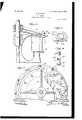
- FIG. 1 is a sectional elevation of a portion of a turbine, showing a connecting device for the purpose set forth constructed in accordance with this invention.
- Fig. 2 is a sectional plan of a portion of a turbine, showing the arrangement of the connecting means for the gates as constructed in accordance With-this invention.
- Fig. 3 is a detail of a gate-arm, broken away, showing the arrangement of the connecting means in relation therewith.
- Fig. 4 is an elevation of the gateconnecting means constructed in accordance with this invention and what is termed an adjustable eccentric connecting member.
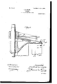
- Fig. 5 is a sectional detail showing the arrangement of the connecting means for the gates as applied between the gates and the operatingevers therefor.
- 1 denotes the crown-plate; 2, the base-plate; 3, the operating-ring for the gates 4, the gates; 5, the gate-arms, provided with the lugs 6,
- 1":L denotes an arm and a hub; 2a, a rack which is engaged by a pinion for operating gates; 3a, a tap-bolt which passes through the inner end of the gate-operating lever; 4a, a swell or IOO ing member hereinafter referred to passes; 6, a gate operating lever g 7 a, a lug on the upper outside edge of the gate through which the connecting member hereinafter referred to passes, said lug 7 a having a circular opening; 8a, a gate; 9a, a hinge or gate-bolt on which the gate oscillates; 10, columnbolts for separating and holding in position the base and dome plates of the turbine; 12, the dome-plate, and 13a the inclined ovalshaped slots formed in the dome-plate.
- the foregoing parts are of known construction in turbines. Only one gate-operating lever 6a and gate 8t is shown; but it will be understood that in a turbine as many gate-operating levers are employed as
- the adjustable connection according to this invention between the gates of the turbine and their operating means and which will enable the gates to open simultaneously and move in unison throughout their entire range of movement consists of an adjustable eccentric connecting member formed with a concentric portion 11, an intermediate portion 12, eccentrically connected at its upper end to the lower end of the concentric portion 11, a laterally-extending flange 12 on one end of the eccentric portion 12, and a nip portion 13, extending from said eccentric portion 12 and which is adapted to be engaged by an instrument when adjusting said connecting member.
- the concentric portion 11 of the adjustable connecting member is screw-threaded, as at 14, and upon said screw-threaded end 14 is mounted a clamping-nut 15 for securing said member in position.
- the concentric portion 11' is adapted, as before stated, to extend through the apertured lug 10 and when said member has been adjusted in a manner as hereinbefore referred to the shoulder 16, formed by the top of the eccentric portion 12, abuts against the lower face of the lug 10, so that when the nut 15 is screwed home it is evident that the adjustable connecting member is clamped or secured to the lug 10.
- the manner in which the gates are connected to the operating levers therefor, through the medium of the adjustable connecting member is as follows:
- the connecting member is inserted down through the lug 5a on the outer end of the lever 6a through the slot in the dome-plate and the lug 7 af on the gate 8, and said member is turned until the shoulder 16 rests on the top of the lug 7a.
- the nut 1'5 is then screwed home and which securely clamps the adjustable eccentric connecting member in position, the flange 12 resting upon the top of the lug 5a on the outer end of the lever 6,
- the connecting member When the connecting member is clamped in position, it cannot move in the lug 7 L, but can move in the opening in the lug 5FL in the outer end of the lever 6a.
- the object of such an arrangement is that in the event of a gate breaking the flange 12/ cannot come down through the lug 5a or the slot in the dome-plate, nor can the nut go up through the lug 7 u. Hence a broken gate cannot pass into the runner-buckets and damage them.
Landscapes
- Engineering & Computer Science (AREA)
- General Engineering & Computer Science (AREA)
- Mechanical Engineering (AREA)
- Chemical & Material Sciences (AREA)
- Combustion & Propulsion (AREA)
- Supercharger (AREA)
Description
6. m. w n .l H I S 2 M. J. m D 2 E T N E T A P 4. O w .v 2 u..m TEMu IN Mlm SDDL JTW C N A N T.. P D.. A
Wa J/` @a u df. l, o f Z o. o,v N mi No. 809,147. vPATENTBD JAN. 2, 1906. o. E. SMITH. TURBINE.
APPLICATION FILED SEPT. 27, 1904.
2 SHEETS--SHEET 2.
UNITED STATES PATENT OFFICE.
CHARLES ELMER SMITH, OF YORK, PENNSYLVANIA, ASSIGNOR TO S. MORGAN SMITH COMPANY, OF YORK, PENNSYLVANIA, A COR- PORATION OF PENNSYLVANIA.
TURBINE.
Specification of Letters Patent.
Patented Jan. 2, 1906.
Application iled September 27, 1904:. Serial No. 226,176.
T0 all when@ it Wawy concern:
Beit known that I, CHARLES ELMER SMITH, a citizen of the United States, residing at York, in the county of York and State of Pennsylvania, have invented new and useful Improvements in Turbines, of which the following is a specification.
This invention relates to certain new and useful improvements in water-wheels of the class known as turbines, which receive water through a plurality of wicket-valves, commonly called gates, placed between the crown and base plates andv uniformly spaced around a circle of proper diameter to admit of their inner ends clearing the runner (wheel proper) when opened to theproper angle and area for delivering the water to the runner; and the obj ect thereof is to provide a new and novel form of adjustable connecting means between the gates and their operating means by which the several gates, constituting a set when connected up, will open simultaneously and move in unison throughout their entire range of movement.
The invention further aims to provide a turbine of the class described with a certain new and novel form of adjustable connecting means for the gates which when employed will make it possible to drill the gate-hinge and column bolt-holes in both the crown and Ybase plates, the gate pin-holes in the lugs on the Iperiphery of the gate-operating ring, or in bot ends of the gate-operating levers, as the lcase may be, so as to enable the gates, plates, levers, and ring to be interchangeable.
The invention .further aims to provide an adjustable gate-connecting means for use in bination and arrangement of parts hereinafter more specically described, illustrated in the accompanying drawings, and particularly pointed out in the claims hereunto appended.
In describing the invention in detail referkenceis had to the accompanying drawings,
forming a part of this specification, and wherein like characters of reference denote corresponding parts throughout the several views, and in which- Figure 1 is a sectional elevation of a portion of a turbine, showing a connecting device for the purpose set forth constructed in accordance with this invention. Fig. 2 is a sectional plan of a portion of a turbine, showing the arrangement of the connecting means for the gates as constructed in accordance With-this invention. Fig. 3 is a detail of a gate-arm, broken away, showing the arrangement of the connecting means in relation therewith. Fig. 4 is an elevation of the gateconnecting means constructed in accordance with this invention and what is termed an adjustable eccentric connecting member. Fig. 5 is a sectional detail showing the arrangement of the connecting means for the gates as applied between the gates and the operatingevers therefor.
Referring to Figs. 1 and 2 of the drawings, 1 denotes the crown-plate; 2, the base-plate; 3, the operating-ring for the gates 4, the gates; 5, the gate-arms, provided with the lugs 6,
having oval-shaped slots 6'; 7, the pivot-pins for the gates; 8, the spider or arms of the operating-ring for the gates, said spider or arms being supported uponthe crown-plate 1; '9, the ordinary central shaft or arbor, and l0 radially-extending lugs formed on the ring 3 and provided with circular openings. The foregoing parts are of known construction in turbines, with the exception of the providing of the gate-arms 5 with the lugs 6, having ovalshaped slots 6', and the providing of the ring 3 with the radially-extendmg apertured lugs 10, having circular openings. The lugs 6, which are a part of the gate arms 5, are adapted when in position to be arranged under the apertured lugs 10.
Referring to'Fig. 5 of the drawings, 1":L denotes an arm and a hub; 2a, a rack which is engaged by a pinion for operating gates; 3a, a tap-bolt which passes through the inner end of the gate-operating lever; 4a, a swell or IOO ing member hereinafter referred to passes; 6, a gate operating lever g 7 a, a lug on the upper outside edge of the gate through which the connecting member hereinafter referred to passes, said lug 7 a having a circular opening; 8a, a gate; 9a, a hinge or gate-bolt on which the gate oscillates; 10, columnbolts for separating and holding in position the base and dome plates of the turbine; 12, the dome-plate, and 13a the inclined ovalshaped slots formed in the dome-plate. The foregoing parts are of known construction in turbines. Only one gate-operating lever 6a and gate 8t is shown; but it will be understood that in a turbine as many gate-operating levers are employed as there are gates.
The adjustable connection according to this invention between the gates of the turbine and their operating means and which will enable the gates to open simultaneously and move in unison throughout their entire range of movement consists of an adjustable eccentric connecting member formed with a concentric portion 11, an intermediate portion 12, eccentrically connected at its upper end to the lower end of the concentric portion 11, a laterally-extending flange 12 on one end of the eccentric portion 12, and a nip portion 13, extending from said eccentric portion 12 and which is adapted to be engaged by an instrument when adjusting said connecting member. The concentric portion 11 of the adjustable connecting member is screw-threaded, as at 14, and upon said screw-threaded end 14 is mounted a clamping-nut 15 for securing said member in position.
The manner in which the gates are connected to the operating ring therefor, through the medium of the adjustable eccentric connecting member, is as follows: The
ates are closed down until the opposing aces thereof abut in the known manner. The concentric portion 11 of the adjustable connecting member is inserted in the apertured lug 10. Said member is then turned until the eccentric portion 12 registers with the opening 6. The adjustable member is then shoved home-that is to say, moved vertically until the screw-threaded portion 14 projects above the lug 10 and the flange 12 abuts against the lug 6. The nut 15 is then mounted upon said portion 14 and screwed home, which securely retains the adjustable eccentric connecting member in position. Of course it will be understood that there is an adjustable eccentric connecting member for each gate. The concentric portion 11'is adapted, as before stated, to extend through the apertured lug 10 and when said member has been adjusted in a manner as hereinbefore referred to the shoulder 16, formed by the top of the eccentric portion 12, abuts against the lower face of the lug 10, so that when the nut 15 is screwed home it is evident that the adjustable connecting member is clamped or secured to the lug 10.
The manner in which the gates are connected to the operating levers therefor, through the medium of the adjustable connecting member, is as follows: The connecting member is inserted down through the lug 5a on the outer end of the lever 6a through the slot in the dome-plate and the lug 7 af on the gate 8, and said member is turned until the shoulder 16 rests on the top of the lug 7a. The nut 1'5 is then screwed home and which securely clamps the adjustable eccentric connecting member in position, the flange 12 resting upon the top of the lug 5a on the outer end of the lever 6, When the connecting member is clamped in position, it cannot move in the lug 7 L, but can move in the opening in the lug 5FL in the outer end of the lever 6a. The object of such an arrangement is that in the event of a gate breaking the flange 12/ cannot come down through the lug 5a or the slot in the dome-plate, nor can the nut go up through the lug 7 u. Hence a broken gate cannot pass into the runner-buckets and damage them.
In connection with the employment of the connecting member with the gate-operating ring it will be stated that the flange 12 comes up under the lug 6 and the nut 15 on the threaded end of the eccentric member is screwed home on top of the lug 10, and by such an arrangement it is evident that a broken gate is prevented from passing into the runner-buckets to damage them.
It will be evident that the eccentricallyconstructed connecting members used in a manner as hereinbefore described will enable the connecting up of the gates with the operating mechanism therefor if the openings for the pivot-pins and connecting members are formed in their respective parts in a slightlyirregular manner. Furthermore, the employment of the connecting members will permit of the various openings for the column-bolts, pivot-pins, and connecting members being bored through the medium of templets and jigs, consequently making such elements of the turbine interchangeable, so that if a part becomes damaged or broken it can be readily replaced.
It is thought the many advantages of an adjustable connecting device between the gates of the turbine and their operating mechanism, as constructed in accordance with the foregoing description, taken in connection with the accompanying drawings, can be thoroughly understood, and it will furthermore be evident that changes, variations, and modifications can be resorted to without departing from the spirit of the invention or sacrificing any of its advantages,
IOO
IIO
and I therefore do not wish to restrict myself to the details of construction as hereinbefore specifically described, and set forth in the anneXed drawings, but reserve the right to make such slight changes, variations, and modifications that properly come within the scope of the protection prayed.
Having thus fully described the invention, what I claim as new, and desire to secure by Letters Patent, is-
1. In a turbine, the combination with the gate-operating mechanism and a set of gates, of an adjustable connecting member between each of the gates and said mechanism, said member provided with concentric and eccentric portions,said concentric portion attached to said mechanism and said eccentric portion connected with a gate.
2. In a turbine, the combination with the gate-operating mechanism and a set of gates, of removable shouldered adjustable connecting members abutting against and attached to said mechanism and connected with the gates.
3. In a turbine, the combination with an apertured operating mechanism for the gates,
and a set of gates each provided with a lug having an oval-shaped opening, of an adjustable connecting member between each of the gates and said mechanism, each of said members provided with a concentric and eccentric portion, said concentric portion adapted to extend in an aperture lformed in said mechanism and said eccentric portion adapt- .ed to extend in the oval-shaped opening of CHARLES ELMER SMITH.
Witnesses:
OHAs. A. OWEN, A. J. GLossHEIMER.
Priority Applications (1)
| Application Number | Priority Date | Filing Date | Title |
|---|---|---|---|
| US22617604A US809147A (en) | 1904-09-27 | 1904-09-27 | Turbine. |
Applications Claiming Priority (1)
| Application Number | Priority Date | Filing Date | Title |
|---|---|---|---|
| US22617604A US809147A (en) | 1904-09-27 | 1904-09-27 | Turbine. |
Publications (1)
| Publication Number | Publication Date |
|---|---|
| US809147A true US809147A (en) | 1906-01-02 |
Family
ID=2877628
Family Applications (1)
| Application Number | Title | Priority Date | Filing Date |
|---|---|---|---|
| US22617604A Expired - Lifetime US809147A (en) | 1904-09-27 | 1904-09-27 | Turbine. |
Country Status (1)
| Country | Link |
|---|---|
| US (1) | US809147A (en) |
-
1904
- 1904-09-27 US US22617604A patent/US809147A/en not_active Expired - Lifetime
Similar Documents
| Publication | Publication Date | Title |
|---|---|---|
| US809147A (en) | Turbine. | |
| US979811A (en) | Valve. | |
| US310459A (en) | Ttpon-tbent | |
| US622592A (en) | Ernst max berger | |
| US41567A (en) | Improvement in water-wheels | |
| US1298611A (en) | Periscope. | |
| US83579A (en) | Improved water-wheel | |
| US1017224A (en) | Feed-indicator for valves. | |
| US97035A (en) | Improvement in deaiif-pipb machines | |
| US144270A (en) | Improvement in watches | |
| US929367A (en) | Three-way valve. | |
| US73937A (en) | stb dm an | |
| US525862A (en) | Bicycle-bell | |
| US923402A (en) | Balancing-machine. | |
| US512244A (en) | John k | |
| US48694A (en) | Improvement in water-wheels | |
| US854586A (en) | Compass-handle-adjusting device. | |
| US1451694A (en) | Wicket-gate-adjusting means | |
| US48995A (en) | Improvement in faucets | |
| USRE3169E (en) | Improvement in water-wheels | |
| US70991A (en) | Improvement in violins and other bow instbtjments | |
| US531879A (en) | Albert f | |
| US89363A (en) | Improvement in turbine water-wheels | |
| US81557A (en) | Leonard s | |
| US71344A (en) | Julius vom hope |