US809127A - Station-meter index. - Google Patents
Station-meter index. Download PDFInfo
- Publication number
- US809127A US809127A US29096104A US1904290961A US809127A US 809127 A US809127 A US 809127A US 29096104 A US29096104 A US 29096104A US 1904290961 A US1904290961 A US 1904290961A US 809127 A US809127 A US 809127A
- Authority
- US
- United States
- Prior art keywords
- cylinder
- gear
- segment
- dial
- shaft
- Prior art date
- Legal status (The legal status is an assumption and is not a legal conclusion. Google has not performed a legal analysis and makes no representation as to the accuracy of the status listed.)
- Expired - Lifetime
Links
- 230000007246 mechanism Effects 0.000 description 12
- 238000010276 construction Methods 0.000 description 3
- 238000004519 manufacturing process Methods 0.000 description 1
- 239000002184 metal Substances 0.000 description 1
Images

Classifications
-
- E—FIXED CONSTRUCTIONS
- E21—EARTH OR ROCK DRILLING; MINING
- E21B—EARTH OR ROCK DRILLING; OBTAINING OIL, GAS, WATER, SOLUBLE OR MELTABLE MATERIALS OR A SLURRY OF MINERALS FROM WELLS
- E21B25/00—Apparatus for obtaining or removing undisturbed cores, e.g. core barrels or core extractors
Definitions
- DONALD MODONALD and LYNN MASON ScoFIELD citizens of the United States, residing at Albany, in the county of Albany and State of New York, have invented new and useful Improvements in Station-Meter 1ndexes, of which the following is a speciiication.
- This invention relates to certain new and useful improvements in what are known as station-meter indexes, and has for its ob* ⁇ jects to provide certain novel combinations and operations of parts and details of construction in a device of this character comprising an observation-dial, time mechanism, registering mechanism, and a recording device or telltale, and the mechanism operating these various parts.
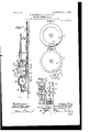
- FIG. 1 is a view in elevation of a complete index constructed according to our invention.
- Fig. 2 is a central vertical sectional .view of the same.
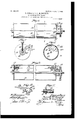
- Fig. 3 is a view in eleva- Fig. 4 is a view of the opposite side of said dialring to that shown byFig. 3 and also showing a cooperative gear.
- Fig. 5 is a sectional elevation of two of the dial-rings and a coperative gear.
- Fig. 6 is a side elevation of the recording-cylinder.
- Fig. 7 is a section on the line 7 7 of Fig. 6.
- Fig. S is a section on the line 8 8 of Fig. 6.
- Fig. 9 is a longitudinal section of the recording-cylinder.
- Fig. 10 is a detail of one end of the swinging segment, and
- Fig. 11 is a detail view showing the means for locking the worm-gear to the threaded bar.
- the bottom or base plate 2 has an extension 4 supporting a chain of gears 5, the outermost gear of which is intended to form the connection from the secondary shaft of the station-meter to the index.
- Mounted on the upper or face plate 1 is an observation-dial 7, on the shaft of which is a gear 8, meshing with intermediate gearing, which in turn is in mesh with the chain of gears 5.
- the dial is provided around its face with an inner and outer circular series of numbers, the numbers on the inner circle corresponding in position to those on the outer circle, but being sixty times greater.
- the outer circle of iigures indicates the actual number ofl cubic feet of gas produced, while the inner circle, over which the hand also sweeps, shows the registration for an hour.
- the rate at which the meter is registering per hour may be ascertained by Observation of the dial for one minute. For instance, if in one minute the hand passes from 0 to 1,000 on the outer circle it will indicate 60,000 on the inner circle, showing that the meter is registering sixty thousand cubic feet of gas per hour.
- dial-rings 11 and i which comprises series of dial-rings 11 and i provided around their periphery with numbers running consecutively from 0 to 9.
- Each of the dial-rings has on opposite sides two metal disks, one of which, 12, is in the form of a gear-wheel, being provided with twenty gear-teeth of standard pitch.
- the other disk 13 is provided in its periphery with a notch 14 and on its outer face with a two-toothed flat segment 15 of a twentytooth gear, the outer peripheryo'f which segment coincides with the periphery of the disk 13 and the toothed slot of which coincides with the tooth-slot 14 in said disk.
- One of the disks or gears 16 on the dial-ring carrying numbers representing hundreds is in mesh with the eight-toothed gear 17, .[ixedly secured on a shaft 18, which is supported in bearings on the under side ofthe face-plate 1. On the end of said shaft 1S is a bevel-gear 19, which meshes with a similar bevel-gear 2O on a shaft 21, which shaft also carries a straight gear 22. By means of interposed gear-wheels 23 the gear-wheel 22 is operatively geared with the operating-gear 8 of the observationdial.
- a shaft 24 On the opposite side of the registering mechanism to that at which the shaft 1S is located is mounted a shaft 24, which is supported in suitable bearings on the under side of the face-plate 1, and on this shaft 24 are mounted at intervals gears 25, each of which has eight teeth, four of said teeth being wide and four narrow and said wide and narrow teeth being arranged in alternation.
- gears 25 each of which has eight teeth, four of said teeth being wide and four narrow and said wide and narrow teeth being arranged in alternation.
- the disk or gear 12 of one dial-ring is located adjacent to but at a slight distance from the disk 13 of the adjacent dial-ring,
- said disk 13 as stated, having a single toothslot 14.
- the gears mesh with the gears 12 of the respective dial-rings, the arrangement being such that the narrow teeth 26 can always mesh with the teeth of the gear 12, the width of these teeth permitting them to enter the space between the disk 13 and the gear 12, but two of the wide teeth 27 of each gear 25 normally bear against the periphery of the disk 13, and in this position said gears 25 are prevented from rotation until in the rotation of the disk 13 the segment 15 engages one of the narrow teeth 26 in mesh with the gear 12, and thus rotates the gear 25, the broad tooth 27 adjacent to the narrow tooth 26 which was engaged by the segment 15 entering the tooth-slot 14 in the disk 13.
- the registeringdials operate in the usual manner of this character of devices, each registering-dial being rotated from the preceding dial, commencing at the dial bearing the numbers representing hundreds. In other words, each complete revolution of the hundreds-dial will operate to move the thousands-dial one point or number, and when the thousands-dial has been given a complete revolution it will operate to move the tens-of-thousands-dial to advance one point or number, and so on.
- Two of the dials (indicated, respectively, by the immerals 28 and 29) represent units and tens, and these dials are stationary, as the device is not intended to register below one hundred.
- observation-dial is substantially indicatedby its name,- but it may be stated that it is marked off to indicate the number of cubic feet of gas produced per hour by observation of one minute.
- the registering mechanism is intended to indicate the total amount of gas produced during any given length of time, or, in other words, to the limit of the capacity of the mechanism to register.
- ten dial-rings are used on the registering device, as shown in the drawings, but any number of these dial-rings greater or less than that named could be employed.
- One of the gear-wheels 30 in the chain of gears 23 is provided with a shaft 31, on the upper end of which is a worm 32, which meshes with a worm-gear 33, which is loosely mounted on the end of a threaded bar 34.
- the threaded bar 34 is mounted in upright bearings 35 36, 'forming integral parts of bearing-plates 37, secured to the upper side of the face-plate 1.
- the worm-gear 33 is loosely mounted on a reduced portion of the threaded shaft 34, and between the bearing 35 and said worm-gear is provided a j am-nut 38, mounted on a screw-threaded portion of said reduced portion of the threaded rod, so that by turning the jam-nut 38 away from the wormgear 33 the threaded bar may be turned independently of said gear to give an adjustment of less than one thread.
- This recorder comprises a cylinder 39, constructed as hereinafter described, said cylinder being loosely mounted on a shaft 40, which in turn is mounted in bearings 41 42, secured on the upper side of the face-plate.
- the bearing 4-2 is a split bearing, one of its members 43 being pivotally secured at 44 to the face-plate, being provided with a curved slot 45, through which extends a set-screw 46, which engages into the 'face-plate. By loosening ⁇ the set-screw 46 the bearing-piece 43 may be turned to one side to permit the cylinder 39 to be lifted out of its bearings.
- the cylinder 39 is provided at one end with a hub 47, which is provided with a screwthreaded aperture fo receive a clampingscrew 48, which clamping-screw preferably projects beyond the face of the cylinder and affords a convenient means for adjusting the position of the same, as will hereinafter appear.
- Said clamping-screw is adapted to be screwed into engagement with the shaft 40, and thus bind the cylinder thereto.
- Mounted on the shalt 40 adjacent to the hub 47 is a worin-gear 49.
- a clock the mechanism of which is connected, by means of interposed gearing, with a gear-wheel 51, secured on an upright shaft 52, on the upper end of which is a worm 53, which is in mesh with the wormgear 49, mounted on the shaft 40 of the recorder.
- the relation of the gearing between the clock and cylinder is such that said cylinder will be given one complete revolution in. every twenty-four hours.
- rl ⁇ he cylinder 39 is designed to carry a paper chart,which chart is ruled with horizontal cordinates representing time and vertical cordinates representing cubic feet. In order to secure this chart about the cylinder, we have provided the following construction of cylinder.
- This segmental portion of the cylinder is adapted to swing on its pivots and is provided near opposite ends with radial plates 56 57 each of which carries a short tube 58, forming a housing for a spring-controlled pin 59, which is adapted to spring out into a hole 60 to maintain the segment in a closed position.
- a spring-controlled pin 59 which is adapted to spring out into a hole 60 to maintain the segment in a closed position.
- an arm 63 having a bent outer end 64 projecting a slight distance beyond the cylinder, whereby by inserting the finger under said bent end the swinging segment may be opened, the pin 62 being guided in the slot 6l.
- a screw 66 for guiding the other end of the swinging segment we provide a curved slot 65 in the opposite end of the cylinder to that referred to, through which slot we pass a screw 66, which is screwed into the plate 56 of the swinging segment.A
- the ends of the swinging segment project a slight distance beyond the radial plates 56 and 57, and said projecting portions are adapted in the closed position of the swinging segment to rest upon shoulders 67, formed on the inner sides of each of the end disks 55.
- a bar 68 Extending between the ends of the cylinder and secured at opposite ends thereto is a bar 68, which extends parallel with one edge portion 69 of the part of the cylinder from which the segment has been removed, and said bar projects slightly beyond the edge portion 69 and is also out of contact with the same, providing a space 70.
- a bar 71 Mounted parallel with the threaded bar 34 and supported in bearings from the under side of the faceplate 1 is a bar 71,' on which is slidably and pivotally mounted a carriage 72, provided on its inner face with a semicylindrical threaded portion 73, which threaded portion is adapted to engage with the threads of the bar 34.
- the carriage 7 2 is provided at its outer end with bearings 74, in which is mounted a rod 75, and on said rod is pivot'ally mounted an arm 76, on the outer end of which is provided a slit ring 77, in which is held by friction a pen or pencil 78, which is adapted to bear upon the chart, (hereinbefore referred to and indicated by 79.)
- the carriage is held in engagement with the threaded bar 34 by its own weight, and the weight of the arm 76 is sufficient to maintain the pencil 78 in contact with the chart.
- a spring-catch 80 On the upper side of the carriage we provide a spring-catch 80, which is adapted to spring over the upper end of the arm 76 when the same is lifted to remove the pencil from contact with tne chart and hold the arm in this position, this being desirable when it is required to remove one chart and insert another upon the cylinder.
- the bearing 36 at one end of the threaded bar 34 is provided with an inwardly-projecting portion 81, the upper side of.
- our improved index not only provides an observation-dial and a registering mechanism, but also combined with these mechanisms and with a clock mechanism is a recorder which will indicate the registration of gas bya meter for twentyfour hours or during any part of the twentyfour hours, showing any changes in the rate of production and furnishing a basis for correction due to changes in pressure or temperature at any time during the day.
- the recording device could be easily arranged to show the registration for more than one day. For instance, it maybe arranged to show the registration for a number of days on one chart either by the use of a chart ruled to take care of a greater registration or by restarting the pen on the same chart, or in lieu of these the speed of the threaded bar 34 could be changed.
- a further function of the spring-catch 8O may be mentioned-that is to say, in the operative position of the parts as shown by Fig.2 said spring bears against the rear side of the arm 76, and thus operates to hold the marking instrument in yielding contact with the surface of the chart. This is especially useful when a pencil is employed.
- a station-meter index in combination with a revolving cylinder adapted to carry a chart, a threaded shaft, a recording instrument operated by said shaft, a gear loosely mounted on said shaft, a jam-nut having screw-threaded engagement therewith and coperating with said gear for the purpose described, and means for operating said gear.
- a recorder comprising a shaft and means for rotating the same, a cylinder loosely mounted on said shaft and adapted to carry a chart, a bindingscrew carried by said cylinder and projecting radially outward beyond the same and adapted t0 engage said shaft, a recording instrument cooperating with said recorder-cylinder, and means for operating said recording instrument.
- a recorder comprising a cylinder having a swinging segment to yieldingly engage the ends of the cylinder for holding said segment in its clamping position.
- a recorder comprising a cylinder having a swinging segment for clamping a chart to the cylinder and provided in its ends with recesses, and springpressed pins carried by said segment and adapted to engage in said recesses for holding said segment in its clamping position.
- a recorder comprising a cylinder having a portion thereof cut away, a segment pivotally mounted in the ends of the cylinder and adapted to close against one edge of the cut-away portion of the cylinder, and a bar extending parallel with such edge but at a distance therefrom, substantially as described.
- a recorder comprising a cylinder having a segment thereof removed and pivotally mounted in the ends of the cylinder, radial plates projecting inward from said segment near the ends thereof, means carried by said plates and engaging the ends of the cylinder for holding the segment in a closed position, and a lifting device projecting through a curved slot in one end of said cylinder and secured to one of said plates for lifting said segment.
- a station-meter index in combination with a record er-drum and means for rotating the same, a threaded shaft and means for rotating the same, a slidably-mounted carriage in mesh with said shaft, a recording instrument pivotally mounted intermediate its ends on said carriage and adapted to coperate with said recorder-drum, and a spring on said carriage adapted to engage the outer end of said instrument for holding it out of contact with said recorder-drum and to bear against the rear side of said instrument to hold it in yielding contact with said recorderdrum.
Landscapes
- Life Sciences & Earth Sciences (AREA)
- Engineering & Computer Science (AREA)
- Geology (AREA)
- Mining & Mineral Resources (AREA)
- Physics & Mathematics (AREA)
- Environmental & Geological Engineering (AREA)
- Fluid Mechanics (AREA)
- General Life Sciences & Earth Sciences (AREA)
- Geochemistry & Mineralogy (AREA)
- A Measuring Device Byusing Mechanical Method (AREA)
Description
No. 809,127. PATENTED JAN. 2, 1906.
D. MODONALD n L. M. SCOFIELD.
STATION METER INDEX.
APPLICATION FILED APR.Z9, 1904. BENEWED DEU. 8, 1905.
3 SHEETS-SHEET l.
777 e 6A? J2e-w M 0734 N0. 809,127. PATENTED JAN. 2, 1906. D. MGDONALD N L. M. SCOTTBLD.
STATION METER INDEX.
APPLICATION FILED APR.29,1904. RENEWBD DEG.8,1905.
s SHEETS-SHEET 2.
Q ff WW No. 809,127. PATENTED JAN. 2, 1906. D. MUDONALD & L. M. SGOFIELD. STATION METER INDEX.
APPLICATION FILED APR.29, 1904. RENBWED DEO. 8,1905.
3 SHEETS-SHEET. 3. 7gg 6? .tion of one side of one of the dial-rings.
v"UNrrnn s'rnprngnivr OFFICE.
DONALD MODONALD AND LYNN M. SCOFIELD, OF ALBANY. NEW YORK, ASSIGNORS TO AMERICAN METER COMPANY, OF NEW YORK, N. Y., A
CORPORATION OF NEW YORK.
STATION-METER INDEX.
Specification of Letters Patent.
Patented Jan. 2a, 1906.
o (1J/Z whom, t mfctjl/ con/cern:
Be it known that we, DONALD MODONALD and LYNN MASON ScoFIELD, citizens of the United States, residing at Albany, in the county of Albany and State of New York, have invented new and useful Improvements in Station-Meter 1ndexes, of which the following is a speciiication. This invention relates to certain new and useful improvements in what are known as station-meter indexes, and has for its ob* `jects to provide certain novel combinations and operations of parts and details of construction in a device of this character comprising an observation-dial, time mechanism, registering mechanism, and a recording device or telltale, and the mechanism operating these various parts.
In order that the invention may be clearly understood, we have illustrated the same in the accompanying drawings, in which- Figure 1 is a view in elevation of a complete index constructed according to our invention. Fig. 2 is a central vertical sectional .view of the same. Fig. 3 is a view in eleva- Fig. 4 is a view of the opposite side of said dialring to that shown byFig. 3 and also showing a cooperative gear. Fig. 5 is a sectional elevation of two of the dial-rings and a coperative gear. Fig. 6 is a side elevation of the recording-cylinder. Fig. 7 is a section on the line 7 7 of Fig. 6. Fig. S is a section on the line 8 8 of Fig. 6. Fig. 9 isa longitudinal section of the recording-cylinder. Fig. 10 is a detail of one end of the swinging segment, and Fig. 11 is a detail view showing the means for locking the worm-gear to the threaded bar.
Referring now to the drawings, the index vcomprises a frame consisting of two parallel plates 1 2, spaced apart and rigidly secured together by means of posts 3. The bottom or base plate 2 has an extension 4 supporting a chain of gears 5, the outermost gear of which is intended to form the connection from the secondary shaft of the station-meter to the index. Mounted on the upper or face plate 1 is an observation-dial 7, on the shaft of which is a gear 8, meshing with intermediate gearing, which in turn is in mesh with the chain of gears 5. The dial is provided around its face with an inner and outer circular series of numbers, the numbers on the inner circle corresponding in position to those on the outer circle, but being sixty times greater. The outer circle of iigures indicates the actual number ofl cubic feet of gas produced, while the inner circle, over which the hand also sweeps, shows the registration for an hour. Thus the rate at which the meter is registering per hour may be ascertained by Observation of the dial for one minute. For instance, if in one minute the hand passes from 0 to 1,000 on the outer circle it will indicate 60,000 on the inner circle, showing that the meter is registering sixty thousand cubic feet of gas per hour.
10 indicates the registering mechanism,
which comprises series of dial-rings 11 and i provided around their periphery with numbers running consecutively from 0 to 9. Each of the dial-rings has on opposite sides two metal disks, one of which, 12, is in the form of a gear-wheel, being provided with twenty gear-teeth of standard pitch. The other disk 13 is provided in its periphery with a notch 14 and on its outer face with a two-toothed flat segment 15 of a twentytooth gear, the outer peripheryo'f which segment coincides with the periphery of the disk 13 and the toothed slot of which coincides with the tooth-slot 14 in said disk. One of the disks or gears 16 on the dial-ring carrying numbers representing hundreds is in mesh with the eight-toothed gear 17, .[ixedly secured on a shaft 18, which is supported in bearings on the under side ofthe face-plate 1. On the end of said shaft 1S is a bevel-gear 19, which meshes with a similar bevel-gear 2O on a shaft 21, which shaft also carries a straight gear 22. By means of interposed gear-wheels 23 the gear-wheel 22 is operatively geared with the operating-gear 8 of the observationdial. On the opposite side of the registering mechanism to that at which the shaft 1S is located is mounted a shaft 24, which is supported in suitable bearings on the under side of the face-plate 1, and on this shaft 24 are mounted at intervals gears 25, each of which has eight teeth, four of said teeth being wide and four narrow and said wide and narrow teeth being arranged in alternation. As shown, the disk or gear 12 of one dial-ring is located adjacent to but at a slight distance from the disk 13 of the adjacent dial-ring,
TOO
said disk 13, as stated, having a single toothslot 14. The gears mesh with the gears 12 of the respective dial-rings, the arrangement being such that the narrow teeth 26 can always mesh with the teeth of the gear 12, the width of these teeth permitting them to enter the space between the disk 13 and the gear 12, but two of the wide teeth 27 of each gear 25 normally bear against the periphery of the disk 13, and in this position said gears 25 are prevented from rotation until in the rotation of the disk 13 the segment 15 engages one of the narrow teeth 26 in mesh with the gear 12, and thus rotates the gear 25, the broad tooth 27 adjacent to the narrow tooth 26 which was engaged by the segment 15 entering the tooth-slot 14 in the disk 13. As soon as the slot 14 passes out of engagement with said broad tooth the plain surface of the disk 13 will again be engaged by two of the wide teeth 27, and thus the gear 25 will be prevented from turning. It will be understood that the registeringdials operate in the usual manner of this character of devices, each registering-dial being rotated from the preceding dial, commencing at the dial bearing the numbers representing hundreds. In other words, each complete revolution of the hundreds-dial will operate to move the thousands-dial one point or number, and when the thousands-dial has been given a complete revolution it will operate to move the tens-of-thousands-dial to advance one point or number, and so on. Two of the dials (indicated, respectively, by the immerals 28 and 29) represent units and tens, and these dials are stationary, as the device is not intended to register below one hundred.
The purpose of the observation-dial is substantially indicatedby its name,- but it may be stated that it is marked off to indicate the number of cubic feet of gas produced per hour by observation of one minute. The registering mechanism, however, is intended to indicate the total amount of gas produced during any given length of time, or, in other words, to the limit of the capacity of the mechanism to register. As actually constructed ten dial-rings are used on the registering device, as shown in the drawings, but any number of these dial-rings greater or less than that named could be employed.
One of the gear-wheels 30 in the chain of gears 23 is provided with a shaft 31, on the upper end of which is a worm 32, which meshes with a worm-gear 33, which is loosely mounted on the end of a threaded bar 34. The threaded bar 34 is mounted in upright bearings 35 36, 'forming integral parts of bearing-plates 37, secured to the upper side of the face-plate 1. The worm-gear 33 is loosely mounted on a reduced portion of the threaded shaft 34, and between the bearing 35 and said worm-gear is provided a j am-nut 38, mounted on a screw-threaded portion of said reduced portion of the threaded rod, so that by turning the jam-nut 38 away from the wormgear 33 the threaded bar may be turned independently of said gear to give an adjustment of less than one thread. By turning the ain-nut 38 tightly against the worin-gear 33 said worin-gear will be jammed between said nut and the shoulder formed by reducing the end of said bar, and thus the threaded bar 34 and the worm-gear 33 will be compelled to move together.
te have thus briefly described the parts of the device which are operated from the chain of gears 5 receiving motion from the shaft of the meter, it only remaining to state that the dial-hand 9 moves in unison with the dialring 11, carrying the numbers representing hundreds, which dial-ring is operated from the gear-wheel 17.
le will now describe the construction and arrangement of the recorder or telltale, which is operated from the clock mechanism. This recorder comprises a cylinder 39, constructed as hereinafter described, said cylinder being loosely mounted on a shaft 40, which in turn is mounted in bearings 41 42, secured on the upper side of the face-plate. The bearing 4-2 is a split bearing, one of its members 43 being pivotally secured at 44 to the face-plate, being provided with a curved slot 45, through which extends a set-screw 46, which engages into the 'face-plate. By loosening` the set-screw 46 the bearing-piece 43 may be turned to one side to permit the cylinder 39 to be lifted out of its bearings. The cylinder 39 is provided at one end with a hub 47, which is provided with a screwthreaded aperture fo receive a clampingscrew 48, which clamping-screw preferably projects beyond the face of the cylinder and affords a convenient means for adjusting the position of the same, as will hereinafter appear. Said clamping-screw is adapted to be screwed into engagement with the shaft 40, and thus bind the cylinder thereto. Mounted on the shalt 40 adjacent to the hub 47 is a worin-gear 49.
50 indicates a clock the mechanism of which is connected, by means of interposed gearing, with a gear-wheel 51, secured on an upright shaft 52, on the upper end of which is a worm 53, which is in mesh with the wormgear 49, mounted on the shaft 40 of the recorder. The relation of the gearing between the clock and cylinder is such that said cylinder will be given one complete revolution in. every twenty-four hours. rl`he cylinder 39 is designed to carry a paper chart,which chart is ruled with horizontal cordinates representing time and vertical cordinates representing cubic feet. In order to secure this chart about the cylinder, we have provided the following construction of cylinder.
54 indicates a segmental portion of the cylinder, which is pivotally mounted at one side IOO 68 and said edge portion.
in the ends 55 of said cylinder, as indicated at 55a. This segmental portion of the cylinder is adapted to swing on its pivots and is provided near opposite ends with radial plates 56 57 each of which carries a short tube 58, forming a housing for a spring-controlled pin 59, which is adapted to spring out into a hole 60 to maintain the segment in a closed position. For the purpose of lifting the swinging segment we provide a curved slot 6l in one of the disks 55 forming one end of the cylinder, and through this slot passes a pin 62, which engages in the plate 57 of the swinging segment. Mounted on this pin is an arm 63, having a bent outer end 64 projecting a slight distance beyond the cylinder, whereby by inserting the finger under said bent end the swinging segment may be opened, the pin 62 being guided in the slot 6l. For guiding the other end of the swinging segment we provide a curved slot 65 in the opposite end of the cylinder to that referred to, through which slot we pass a screw 66, which is screwed into the plate 56 of the swinging segment.A As shown, the ends of the swinging segment project a slight distance beyond the radial plates 56 and 57, and said projecting portions are adapted in the closed position of the swinging segment to rest upon shoulders 67, formed on the inner sides of each of the end disks 55. Extending between the ends of the cylinder and secured at opposite ends thereto is a bar 68, which extends parallel with one edge portion 69 of the part of the cylinder from which the segment has been removed, and said bar projects slightly beyond the edge portion 69 and is also out of contact with the same, providing a space 70. In placing a chart about the cylinder the segment is opened and the chart is folded at the starting-line and said folded portion is slipped over the edge portion 69 and into the space 70 between the bar The chart is now lapped around the cylinder and folded over the outer edge portion of the swinging segment 54, and said swinging segment is then closed, thus presenting the effective registration surface of the chart in continuous cylindrical form, offering no obstruction to the oint of pen hereinafter referred to and alowing complete and accurate record for one or more revolutions of the cylinder. rlhe pins 59 hold the swinging segment in its closed position; but by a slight pull exerted on the arm 6'3 said swinging segment maybe readily opened to remove the chart. Mounted parallel with the threaded bar 34 and supported in bearings from the under side of the faceplate 1 is a bar 71,' on which is slidably and pivotally mounted a carriage 72, provided on its inner face with a semicylindrical threaded portion 73, which threaded portion is adapted to engage with the threads of the bar 34. The carriage 7 2 is provided at its outer end with bearings 74, in which is mounted a rod 75, and on said rod is pivot'ally mounted an arm 76, on the outer end of which is provided a slit ring 77, in which is held by friction a pen or pencil 78, which is adapted to bear upon the chart, (hereinbefore referred to and indicated by 79.) The carriage is held in engagement with the threaded bar 34 by its own weight, and the weight of the arm 76 is sufficient to maintain the pencil 78 in contact with the chart. On the upper side of the carriage we provide a spring-catch 80, which is adapted to spring over the upper end of the arm 76 when the same is lifted to remove the pencil from contact with tne chart and hold the arm in this position, this being desirable when it is required to remove one chart and insert another upon the cylinder. The bearing 36 at one end of the threaded bar 34 is provided with an inwardly-projecting portion 81, the upper side of. which is beveled, as indicatedl at 82, and the carriage 72 is provided at one side with a lug 83, which is adapted to ride up this beveled side, and thus lift the carriage 7 3 out of engagement with the threaded bar 34 when said carriage has reached the end of its traverse in one direction, thus preventing jamming of the parts. When the carriage 73 has been moved to the end of the threaded bar in starting the record on a new chart, if it be found that the pencil does not rest on the starting-line of the chart the jam-nut 38 may be loosened and the threaded bar 34 turned until the correct position of the pencil is obtained, and said. jam- .nut is again screwed up against the wormgear 33. This refers to having the pencil correctly positioned on the first or starting vertical line of the chart. To secure the correct position relative t0 the pencil of the first or starting horizontal line, the clamping-screw 48 is loosened, when the cylinder 39 may be readily revolved on its shaf t by means of said clamping-screw until the correct position is reached, when the said screw is again turned to bind against the shaft 40.
It will thus be seen that our improved index not only provides an observation-dial and a registering mechanism, but also combined with these mechanisms and with a clock mechanism is a recorder which will indicate the registration of gas bya meter for twentyfour hours or during any part of the twentyfour hours, showing any changes in the rate of production and furnishing a basis for correction due to changes in pressure or temperature at any time during the day. It will be apparent, further, that the recording device could be easily arranged to show the registration for more than one day. For instance, it maybe arranged to show the registration for a number of days on one chart either by the use of a chart ruled to take care of a greater registration or by restarting the pen on the same chart, or in lieu of these the speed of the threaded bar 34 could be changed.
IOO
IIO
ISO
A further function of the spring-catch 8O may be mentioned-that is to say, in the operative position of the parts as shown by Fig.2 said spring bears against the rear side of the arm 76, and thus operates to hold the marking instrument in yielding contact with the surface of the chart. This is especially useful when a pencil is employed.
Having thus fully described our invention, what we claim as new, and desire to secure by Letters Patent of the United States, is-
1. In a station-meter index, in combination with a revolving cylinder adapted to carry a chart, a threaded shaft, a recording instrument operated by said shaft, a gear loosely mounted on said shaft, a jam-nut having screw-threaded engagement therewith and coperating with said gear for the purpose described, and means for operating said gear.
2. In a station-meter index, a recorder comprising a shaft and means for rotating the same, a cylinder loosely mounted on said shaft and adapted to carry a chart, a bindingscrew carried by said cylinder and projecting radially outward beyond the same and adapted t0 engage said shaft, a recording instrument cooperating with said recorder-cylinder, and means for operating said recording instrument.
3. In a station-meter index a recorder comprising a cylinder having a swinging segment to yieldingly engage the ends of the cylinder for holding said segment in its clamping position.
4. In a station-meterindex, a recorder comprising a cylinder having a swinging segment for clamping a chart to the cylinder and provided in its ends with recesses, and springpressed pins carried by said segment and adapted to engage in said recesses for holding said segment in its clamping position.
5. In a station-Ineter index, a recorder comprising a cylinder having a portion thereof cut away, a segment pivotally mounted in the ends of the cylinder and adapted to close against one edge of the cut-away portion of the cylinder, and a bar extending parallel with such edge but at a distance therefrom, substantially as described.
6. Inastation-meter index, arecorder con prising a cylinder having a portion thereof cut away, a segment pivotally mounted in the ends of the cylinder and adapted to close against one edge of the cut-away portion of the cylinder, and a bar extending parallel with such edge but at a distance therefrom and projecting beyond the same, substantially as described.
7. In a station-meter index, a recorder comprising a cylinder having a segment thereof removed and pivotally mounted in the ends of the cylinder, radial plates projecting inward from said segment near the ends thereof, means carried by said plates and engaging the ends of the cylinder for holding the segment in a closed position, and a lifting device projecting through a curved slot in one end of said cylinder and secured to one of said plates for lifting said segment.
S. In a station-meter index, in combination with a recorder-drum, and means for rotatingthc same, a threaded shaft and means for rotating the same, a slid ably-mounted carriage in mesh with said shaft, a recording instrument pivotally mounted on the outer end of said carriage and adapted to cooperate with said recorder-drum, and a spring-catch on said carriage adapted to engage the rear end of said instrument for holding it out of contact with said recorder-drum.
9. In a station-meter index, in combination with a record er-drum and means for rotating the same, a threaded shaft and means for rotating the same, a slidably-mounted carriage in mesh with said shaft, a recording instrument pivotally mounted intermediate its ends on said carriage and adapted to coperate with said recorder-drum, and a spring on said carriage adapted to engage the outer end of said instrument for holding it out of contact with said recorder-drum and to bear against the rear side of said instrument to hold it in yielding contact with said recorderdrum.
In testimony whereof we have hereunto set our hands in presence of two subscribing witnesses.
DONALD MODONALD. LYNN M. SCOFIELD.
Witnesses:
WILLIAM McDoNALD, CHRISTIAN MEYER.
Priority Applications (1)
| Application Number | Priority Date | Filing Date | Title |
|---|---|---|---|
| US29096104A US809127A (en) | 1904-04-29 | 1904-04-29 | Station-meter index. |
Applications Claiming Priority (1)
| Application Number | Priority Date | Filing Date | Title |
|---|---|---|---|
| US29096104A US809127A (en) | 1904-04-29 | 1904-04-29 | Station-meter index. |
Publications (1)
| Publication Number | Publication Date |
|---|---|
| US809127A true US809127A (en) | 1906-01-02 |
Family
ID=2877608
Family Applications (1)
| Application Number | Title | Priority Date | Filing Date |
|---|---|---|---|
| US29096104A Expired - Lifetime US809127A (en) | 1904-04-29 | 1904-04-29 | Station-meter index. |
Country Status (1)
| Country | Link |
|---|---|
| US (1) | US809127A (en) |
Cited By (5)
| Publication number | Priority date | Publication date | Assignee | Title |
|---|---|---|---|---|
| US2655285A (en) * | 1950-01-03 | 1953-10-13 | Albert J Granberg | Liquid dispensing apparatus having protected quantity control mechanism and counter |
| US2659165A (en) * | 1951-04-12 | 1953-11-17 | Edward F Grubola | Educational toy |
| US2861862A (en) * | 1953-06-27 | 1958-11-25 | Philips Corp | Dictation apparatus |
| US3061191A (en) * | 1958-03-03 | 1962-10-30 | Amerline Corp | Manually presettable counting means |
| US20230313731A1 (en) * | 2022-04-04 | 2023-10-05 | Illinois Tool Works Inc. | Anti-Tampering Device for a Degassing Tank Cap |
-
1904
- 1904-04-29 US US29096104A patent/US809127A/en not_active Expired - Lifetime
Cited By (5)
| Publication number | Priority date | Publication date | Assignee | Title |
|---|---|---|---|---|
| US2655285A (en) * | 1950-01-03 | 1953-10-13 | Albert J Granberg | Liquid dispensing apparatus having protected quantity control mechanism and counter |
| US2659165A (en) * | 1951-04-12 | 1953-11-17 | Edward F Grubola | Educational toy |
| US2861862A (en) * | 1953-06-27 | 1958-11-25 | Philips Corp | Dictation apparatus |
| US3061191A (en) * | 1958-03-03 | 1962-10-30 | Amerline Corp | Manually presettable counting means |
| US20230313731A1 (en) * | 2022-04-04 | 2023-10-05 | Illinois Tool Works Inc. | Anti-Tampering Device for a Degassing Tank Cap |
Similar Documents
| Publication | Publication Date | Title |
|---|---|---|
| US809127A (en) | Station-meter index. | |
| US618636A (en) | Registering device | |
| US531817A (en) | Precision-index | |
| US1052940A (en) | High-speed recording-gage. | |
| US517746A (en) | grenfell | |
| US964695A (en) | Meter. | |
| US424185A (en) | Lewis donne and morgan donne | |
| US1205353A (en) | Travel-recorder. | |
| US1085206A (en) | Horological instrument. | |
| US716166A (en) | Calendar. | |
| US66307A (en) | Improved registering steam gauge | |
| US1113801A (en) | Interest-calculator. | |
| US54198A (en) | Improvement in calendar-clocks | |
| US222377A (en) | Improvement in calendar-clocks | |
| US384479A (en) | Register and recorder for revolving shafts | |
| US261388A (en) | Charles e | |
| US873696A (en) | Calendar. | |
| US349025A (en) | Necticut | |
| US551556A (en) | Calendar-clock | |
| US1216201A (en) | Recording-compass. | |
| US942659A (en) | Winding-indicator. | |
| US744173A (en) | Time-recorder. | |
| US565303A (en) | Art of and apparatus for measuring power | |
| US579937A (en) | Island | |
| US565034A (en) | Albert p |