US809117A - Elevator. - Google Patents
Elevator. Download PDFInfo
- Publication number
- US809117A US809117A US26879205A US1905268792A US809117A US 809117 A US809117 A US 809117A US 26879205 A US26879205 A US 26879205A US 1905268792 A US1905268792 A US 1905268792A US 809117 A US809117 A US 809117A
- Authority
- US
- United States
- Prior art keywords
- cage
- beams
- platform
- uprights
- shaft
- Prior art date
- Legal status (The legal status is an assumption and is not a legal conclusion. Google has not performed a legal analysis and makes no representation as to the accuracy of the status listed.)
- Expired - Lifetime
Links
Images

Classifications
-
- B—PERFORMING OPERATIONS; TRANSPORTING
- B65—CONVEYING; PACKING; STORING; HANDLING THIN OR FILAMENTARY MATERIAL
- B65G—TRANSPORT OR STORAGE DEVICES, e.g. CONVEYORS FOR LOADING OR TIPPING, SHOP CONVEYOR SYSTEMS OR PNEUMATIC TUBE CONVEYORS
- B65G67/00—Loading or unloading vehicles
Definitions
- Patented J' an. 2, 1906.
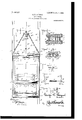
- Figure 1 isla front elevation of an elevator or mine-cage constructed in accordance with my invention.
- Fig. 2 is a side elevation, the near shaft-beam and one of the side pieces of the cage being broken away to show the construction of the pivoted platform and parts carried thereby.
- Fig. 3 is a sectional view through the upper corner of the cage on the line 3 3 of Fig. l.
- Fig. i is a transverse sectional view through the upper part of the cage on the line 4- 4 of Fig. l.
- Fig. 5 is a detail view of one of the safety-catches.
- Fig. 6 is a detail view' of the locking-dogs for holding the car upon the pivoted platform.
- Fig. 7 is a detail view of one of the trip-levers for operating the locking-dogs.
- My improved mine-cage is adapted to operate in a shaft provided with the usual vertical beams or uprights A A, suitably supported at opposite sides of the shaft, and which beams or uprights form the tracks or guides on which the elevator runs.
- I In constructing the cage in accordance with my invention I provide an upper pair of horizontal beams B B, forming the top of the cage, and a similar pair of beams B B', forming the bottom of said cage, and connect said upper and lower beams together by straight metal plates or flat bars U.
- the upper beams, as well as the lower, are spaced apart and are securely held in their relative positions by means of rectangular castings c, interposed between said beams near the opposite ends thereof and bolted. thereto, as shown in Fig. 3.
- the beams are spaced apart to receive the uprights A of vthe shaft between the ends thereof, and as the connectingplates or flat bars O, which form the sides of the cage, are attached to the ends of said beams they are disposed at the opposite sides of the uprights.
- Wear-plates c in the form of angle-plates are bolted in .place between the ends of the beams B B and B B', as indicated in Fig. 8, and embrace the shaft-beams orv uprights A.
- the plates or flat bars O are secured to the upper and lower beams of the cage by corner-braces or angle-plates c2 and c3, the latter serving, with extensions c4 of said flat bars, to form the means of connection for the hoisting and lowering devices hereinafter mentioned; also, that the lower ends of the plates or fiat bars C are extended under the lower beams B to strengthen the connection at this point.
- the parts described combine to produce a very stron and durable cage which will slide freely in t e shaft upon and between the beams or uprights A and is of light construction consistently with the required strength, such cage beingdesigned to support and carry the pivoted piatfrom hereinafter described.
- the elevator connections for the hoisting and lowering cable comprise the chains d, eX- tending from the brackets c3 c4 and attached to a spreader-plate d', the latter carrying the eyebolt cl2, to which the cable d3 is attached.
- the eyebolt has the usual compression-spring d4 interposed between the nut-held washer d5 and aforesaid spreader-plate d. This is one of the usual forms of connection,
- bearing-blocks e e mounted upon the lower beams B of the cage are bearing-blocks e e, in which is journaled a rock shaft f, adapted to pivotally support the platform G of the cage.
- the platform is made up in any suitable manner, in the present instance of the horizontal beams g and connecting cross-beams g, and upon said platform are secured the trackrails 7L, upon which the cars run.
- the platform is supported from the rock-shaft f by means of triangular plates I, having outwardly-projecting flanges i at their upper ends by which they are secured to said plat- IOO IIO
- connection being reinforced by means of angle-bars t, as shown in Fig. 1.
- the triangular plates I are reinforced at their lower ends, where they are fixed to the shaft, by means of plates i2.
- This particular manner of supporting the platform permits the same to be swung or tilted at either side of the cage, so as to facilitate the discharge of the contents of the car atupper end of the mine-shaft, and in order to support the platform horizontally during the travel of the cage in the shaft said platform is provided with shoes4 y', secured in pairs at opposite sides thereof and disposed to travel at opposite sides of the beams or uprights A.
- the beams or uprights A of the mineshaft are cut away at their inner sides, as at a, whereby the shoes may pass the beams, the beams or uprights being cut away for the purpose only at such points where the cage stops to take on and let off cars.
- a pair of locking-dogs M are pivotally supported in the platform and so located that the same will be swung automatically to engage the wheels of the car when the elevator leaves the bottom landing.
- These dogs each consist of a bar fixed at its lower end on a shaft m, bent forwardly at an angle intermediately, as at m, and bifurcated at its upper end to provide the oppositely-curved members m2 m2, which latter engage the inclined portion of the periphery of the wheels 0 of the car, passing in between the wheels at opposite sides of the car.
- the dogs are adapted to swing away from the carin disengaging the wheels and are operated in this direction by means of trip-levers N, fixed on the opposite ends of the shafts m and extending toward the center of the platform parallel with the ends thereof, said trip-levers having outwardly-projecting engaging members n, Y by which they are operated automatically by contact with bottom landing.
- trip-levers N fixed on the opposite ends of the shafts m and extending toward the center of the platform parallel with the ends thereof, said trip-levers having outwardly-projecting engaging members n, Y by which they are operated automatically by contact with bottom landing.
- These locking-dogs are normally brought to an upright position for engaging the car-wheels by means of a compression-spring s, attached thereto and extending therebetween, and in this latter position of the dogs the free ends of the trip-levers are downwardlyinclined, as shown in Figs. 1 and 2 of the drawings.
- safety-catches p are attached to the upper part of the elevator-frame and disposed at opposite sides of the beams or uprights A, so as to engage the latter and hold the cage suspended thereby.
- These catches are fixed on shafts p', the latter having bearings in brackets g, attached to the beams B and at their ends in the corner-braces c2, (see Fig. 5,) such bearings being at opposite sides of the catches, so as to firmly support the same.
- the shafts p are provided with outwardlyprojecting fixed arms p2, by which they are connected to a transverse rod p3, to which latter the operating rod p4 is attached.
- the operating-rod is connected by a chain p5 and interposed spring p to the spreader-plate d of the cage connections for the hoisting and lowering apparatus.
- the tendency of the spring p7 is to depress the rod p3, and consequently move the catches into engagement with the uprights, and that the connection of the operating-rod with the hoisting and lowering device is such that when the elevator is suspended from said latter device the catches will be out of engagement with the uprights.
- the spring p7 will depress the rod p3, andthe latter being connected to the transverse rods p will turn the latter to bring the catches into engagement with the uprights A of the mineshaft, the engagement being such as to support the cage against falling.
- the interposed spring p permits the safety device to be operated manually by drawing upon the pull-cords o.
- the safety-catches p are in the shape of cams having the engaging projections or members p8 and 0, the member p8 being bifurcated to provi e points or spurs, while the member p9 is thicker and provided with a straight edge, so as not to penetrate the beam to any great extent.
- the member p8 is in advance of the member p9, whereby the points of the former will when the catches or cams are swung against the beams penetrate the beam and bring the other or stronger member against the same to quickly and effectually stop the descent of the cage.
- dogs pivoted in the platform and adapted to engage the Wheels of a oar run thereon, said dogs comprising a bar bifuroated at its upper or free end to provide oppositely-ourved enzo the center of the platform at opposite lends of 2 5 the latter, arms projecting outwardly at the free ends of the levers, and a spring adapted to hold the dogs normally upright with the levers at a downward inclination, substantially as shown and for the purpose set forth.
Landscapes
- Engineering & Computer Science (AREA)
- Aviation & Aerospace Engineering (AREA)
- Mechanical Engineering (AREA)
- Types And Forms Of Lifts (AREA)
- Lift-Guide Devices, And Elevator Ropes And Cables (AREA)
Description
No. 809,117. PATENTED JAN. 2, 1906. G. R. LAYMAN.
BLEVTOR. APPLICATION FILED JULY 8, 190s 2 SHEETS-SHEET 1.
n j l e f e T. o@ L @a PATENTED JAN. 2, 1906.
Noy 809,117.
G. R. LAYMAN.
. ELEVATOR.
APPLICATION FILED JULY s. 1905.
2 SHEETS-SHEET 2.
wit/www0 UNITED STATES PATENT OFFIOE.
ELEVATOR.
Specification of Letters Patent.
Patented J' an. 2, 1906.
Application lefl July 8, 1905. Serial No. 268,792.
T0 00M whom it neet-l concern..-
Be it known that I, GEORGE R. LAYMAN, a
.citizen of the United States, residing at Lin- .to provide a mine elevator or cage which shall be simple in construction, strong and durable, will greatly facilitate the operation of" loading the cars thereon and unloading them therefrom, and will provide against serious accident in case the hoisting and lowering cable should break.
Other objects and advantages of the invention will hereinafter appear and the novel features of construction specifically pointed out in the claims. Y
In the accompanying drawings, which form a part of this specification, Figure 1 isla front elevation of an elevator or mine-cage constructed in accordance with my invention. Fig. 2 is a side elevation, the near shaft-beam and one of the side pieces of the cage being broken away to show the construction of the pivoted platform and parts carried thereby. Fig. 3 is a sectional view through the upper corner of the cage on the line 3 3 of Fig. l. Fig. i is a transverse sectional view through the upper part of the cage on the line 4- 4 of Fig. l. Fig. 5 is a detail view of one of the safety-catches. Fig. 6 is a detail view' of the locking-dogs for holding the car upon the pivoted platform. Fig. 7 is a detail view of one of the trip-levers for operating the locking-dogs.
Like letters of reference indicate like parts in all the views of the drawings.
My improved mine-cage is adapted to operate in a shaft provided with the usual vertical beams or uprights A A, suitably supported at opposite sides of the shaft, and which beams or uprights form the tracks or guides on which the elevator runs.
In constructing the cage in accordance with my invention I provide an upper pair of horizontal beams B B, forming the top of the cage, and a similar pair of beams B B', forming the bottom of said cage, and connect said upper and lower beams together by straight metal plates or flat bars U. The upper beams, as well as the lower, are spaced apart and are securely held in their relative positions by means of rectangular castings c, interposed between said beams near the opposite ends thereof and bolted. thereto, as shown in Fig. 3. The beams are spaced apart to receive the uprights A of vthe shaft between the ends thereof, and as the connectingplates or flat bars O, which form the sides of the cage, are attached to the ends of said beams they are disposed at the opposite sides of the uprights. Wear-plates c in the form of angle-plates are bolted in .place between the ends of the beams B B and B B', as indicated in Fig. 8, and embrace the shaft-beams orv uprights A. It will be noted that the plates or flat bars O are secured to the upper and lower beams of the cage by corner-braces or angle-plates c2 and c3, the latter serving, with extensions c4 of said flat bars, to form the means of connection for the hoisting and lowering devices hereinafter mentioned; also, that the lower ends of the plates or fiat bars C are extended under the lower beams B to strengthen the connection at this point.
The parts described combine to produce a very stron and durable cage which will slide freely in t e shaft upon and between the beams or uprights A and is of light construction consistently with the required strength, such cage beingdesigned to support and carry the pivoted piatfrom hereinafter described.
The elevator connections for the hoisting and lowering cable comprise the chains d, eX- tending from the brackets c3 c4 and attached to a spreader-plate d', the latter carrying the eyebolt cl2, to which the cable d3 is attached. The eyebolt has the usual compression-spring d4 interposed between the nut-held washer d5 and aforesaid spreader-plate d. This is one of the usual forms of connection,
Mounted upon the lower beams B of the cage are bearing-blocks e e, in which is journaled a rock shaft f, adapted to pivotally support the platform G of the cage. The platform is made up in any suitable manner, in the present instance of the horizontal beams g and connecting cross-beams g, and upon said platform are secured the trackrails 7L, upon which the cars run. The platform is supported from the rock-shaft f by means of triangular plates I, having outwardly-projecting flanges i at their upper ends by which they are secured to said plat- IOO IIO
form, such connection being reinforced by means of angle-bars t, as shown in Fig. 1. The triangular plates I are reinforced at their lower ends, where they are fixed to the shaft, by means of plates i2. This particular manner of supporting the platform permits the same to be swung or tilted at either side of the cage, so as to facilitate the discharge of the contents of the car atupper end of the mine-shaft, and in order to support the platform horizontally during the travel of the cage in the shaft said platform is provided with shoes4 y', secured in pairs at opposite sides thereof and disposed to travel at opposite sides of the beams or uprights A. To permit of the tilting movement of the platform, the beams or uprights A of the mineshaft are cut away at their inner sides, as at a, whereby the shoes may pass the beams, the beams or uprights being cut away for the purpose only at such points where the cage stops to take on and let off cars.
To hold the cars stationary on the platform during the travel of the cage in the shaft and at the dumping-point, a pair of locking-dogs M are pivotally supported in the platform and so located that the same will be swung automatically to engage the wheels of the car when the elevator leaves the bottom landing. These dogs each consist of a bar fixed at its lower end on a shaft m, bent forwardly at an angle intermediately, as at m, and bifurcated at its upper end to provide the oppositely-curved members m2 m2, which latter engage the inclined portion of the periphery of the wheels 0 of the car, passing in between the wheels at opposite sides of the car. The dogs are adapted to swing away from the carin disengaging the wheels and are operated in this direction by means of trip-levers N, fixed on the opposite ends of the shafts m and extending toward the center of the platform parallel with the ends thereof, said trip-levers having outwardly-projecting engaging members n, Y by which they are operated automatically by contact with bottom landing. These locking-dogs are normally brought to an upright position for engaging the car-wheels by means of a compression-spring s, attached thereto and extending therebetween, and in this latter position of the dogs the free ends of the trip-levers are downwardlyinclined, as shown in Figs. 1 and 2 of the drawings.
I provide the cage with an automatic safety device for arresting its fall in case there should be a break in the hoisting and lowering cable or the machinery operating the same. For this purpose safety-catches p are attached to the upper part of the elevator-frame and disposed at opposite sides of the beams or uprights A, so as to engage the latter and hold the cage suspended thereby. These catches are fixed on shafts p', the latter having bearings in brackets g, attached to the beams B and at their ends in the corner-braces c2, (see Fig. 5,) such bearings being at opposite sides of the catches, so as to firmly support the same. The shafts p are provided with outwardlyprojecting fixed arms p2, by which they are connected to a transverse rod p3, to which latter the operating rod p4 is attached. The operating-rod is connected by a chain p5 and interposed spring p to the spreader-plate d of the cage connections for the hoisting and lowering apparatus. There is also a helical spring p7, which encircles the operating-rod p4 and is interposed between the transverse rod p3 and a bearing-plate b, attached to the beams B B, said bearing-plate also serving as a guide for the operating rod. It will be noted that the tendency of the spring p7 is to depress the rod p3, and consequently move the catches into engagement with the uprights, and that the connection of the operating-rod with the hoisting and lowering device is such that when the elevator is suspended from said latter device the catches will be out of engagement with the uprights. In this manner when the draft on the operating-rod is released-for instance, in case the hoisting and lowering cable breaks-the spring p7 will depress the rod p3, andthe latter being connected to the transverse rods p will turn the latter to bring the catches into engagement with the uprights A of the mineshaft, the engagement being such as to support the cage against falling. The interposed spring p permits the safety device to be operated manually by drawing upon the pull-cords o.
The safety-catches p are in the shape of cams having the engaging projections or members p8 and 0, the member p8 being bifurcated to provi e points or spurs, while the member p9 is thicker and provided with a straight edge, so as not to penetrate the beam to any great extent. The member p8 is in advance of the member p9, whereby the points of the former will when the catches or cams are swung against the beams penetrate the beam and bring the other or stronger member against the same to quickly and effectually stop the descent of the cage.
From the foregoing it will be readily seen that I provide a mine cage which is extremely simple in construction and operation, is strongly built7 will run freely and smoothly in the shaft, will facilitate the handling of the cars, and will prevent serious accident in case of a break or disarrangement of the hoisting and lowering apparatus.
Having thus described my invention,what I claim as new, and desire to secure by Letters Patent, is-
l. In a mine-cage, the combination with the uprights or guide-rails of the elevatorshaft having passage-ways therein, of the cage, a plat orm pivoted therein, vertically- IOO IOS
disposed triangular plates supporting the platform, a rook-shaft to which the triangular plates are fixed and forming a pivot for saiddplates by which the platform may be tilte shoes at the sides of the platform adapted to slide on the uprights and pass through the passage-ways thereof when the platform is tilted, dogs pivoted in the platform and adapted to engage the wheels of a oar run thereon, a spring connecting the dogs to hold them upright or normally in engagement with suoh wheels, and operating-levers connected to the dogs for releasing them, substantially as shown and described.
2. In a mine-cage, the combination with the cage, of a platform pivoted therein, dogs pivoted in the platform and adapted to engage the Wheels of a oar run thereon, said dogs comprising a bar bifuroated at its upper or free end to provide oppositely-ourved enzo the center of the platform at opposite lends of 2 5 the latter, arms projecting outwardly at the free ends of the levers, and a spring adapted to hold the dogs normally upright with the levers at a downward inclination, substantially as shown and for the purpose set forth. 3o
In ltestimony whereof I have signed my name to this specification in the presence of two subscribing witnesses.
GEORGE R. LAYMAN.
Witnesses A. D. CADWALLADER, J. E. JEWETT.
Priority Applications (2)
| Application Number | Priority Date | Filing Date | Title |
|---|---|---|---|
| US26879205A US809117A (en) | 1905-07-08 | 1905-07-08 | Elevator. |
| US279315A US834816A (en) | 1905-07-08 | 1905-09-20 | Safety device for elevators. |
Applications Claiming Priority (1)
| Application Number | Priority Date | Filing Date | Title |
|---|---|---|---|
| US26879205A US809117A (en) | 1905-07-08 | 1905-07-08 | Elevator. |
Publications (1)
| Publication Number | Publication Date |
|---|---|
| US809117A true US809117A (en) | 1906-01-02 |
Family
ID=2877598
Family Applications (1)
| Application Number | Title | Priority Date | Filing Date |
|---|---|---|---|
| US26879205A Expired - Lifetime US809117A (en) | 1905-07-08 | 1905-07-08 | Elevator. |
Country Status (1)
| Country | Link |
|---|---|
| US (1) | US809117A (en) |
-
1905
- 1905-07-08 US US26879205A patent/US809117A/en not_active Expired - Lifetime
Similar Documents
| Publication | Publication Date | Title |
|---|---|---|
| US809117A (en) | Elevator. | |
| US1021898A (en) | Hay stacker and loader. | |
| US449026A (en) | Portable elevator | |
| US387512A (en) | Portable elevator | |
| US826877A (en) | Elevator for barrels and the like. | |
| US333195A (en) | Coal-hoist | |
| US371568A (en) | Dumping mechanism for hoisting apparatus | |
| US552476A (en) | Dumping apparatus | |
| US513862A (en) | Dumping apparatus | |
| US923923A (en) | Hoisting or carrying mechanism for barns. | |
| US766907A (en) | Automatic dumping-cage. | |
| US735965A (en) | Coal-hoist. | |
| US436190A (en) | Hoisting apparatus | |
| US294015A (en) | conrad | |
| US1001818A (en) | Elevator for mines. | |
| US740609A (en) | Combined elevator and dump. | |
| US692888A (en) | Car-dump for elevators in mines. | |
| US473275A (en) | Elevator for mining-cars | |
| US551745A (en) | Tramway for hoisting and dumping apparatus | |
| US594736A (en) | Automatic dumping-cage | |
| US744097A (en) | Package-elevator. | |
| US720265A (en) | Mine-cage. | |
| US415493A (en) | Device for conveying coal | |
| US311671A (en) | Hoisting and conveying apparatus | |
| US507712A (en) | Automatic elevator |