US809113A - Chain. - Google Patents
Chain. Download PDFInfo
- Publication number
- US809113A US809113A US26491005A US1905264910A US809113A US 809113 A US809113 A US 809113A US 26491005 A US26491005 A US 26491005A US 1905264910 A US1905264910 A US 1905264910A US 809113 A US809113 A US 809113A
- Authority
- US
- United States
- Prior art keywords
- block
- body portion
- chain
- links
- coupling
- Prior art date
- Legal status (The legal status is an assumption and is not a legal conclusion. Google has not performed a legal analysis and makes no representation as to the accuracy of the status listed.)
- Expired - Lifetime
Links
- 230000008878 coupling Effects 0.000 description 14
- 238000010168 coupling process Methods 0.000 description 14
- 238000005859 coupling reaction Methods 0.000 description 14
- 238000010276 construction Methods 0.000 description 5
- 238000005096 rolling process Methods 0.000 description 3
- 239000000470 constituent Substances 0.000 description 2
- 238000006073 displacement reaction Methods 0.000 description 2
- 238000004519 manufacturing process Methods 0.000 description 1
- 239000002184 metal Substances 0.000 description 1
- 230000000979 retarding effect Effects 0.000 description 1
- 239000011435 rock Substances 0.000 description 1
Images
Classifications
-
- F—MECHANICAL ENGINEERING; LIGHTING; HEATING; WEAPONS; BLASTING
- F16—ENGINEERING ELEMENTS AND UNITS; GENERAL MEASURES FOR PRODUCING AND MAINTAINING EFFECTIVE FUNCTIONING OF MACHINES OR INSTALLATIONS; THERMAL INSULATION IN GENERAL
- F16G—BELTS, CABLES, OR ROPES, PREDOMINANTLY USED FOR DRIVING PURPOSES; CHAINS; FITTINGS PREDOMINANTLY USED THEREFOR
- F16G13/00—Chains
- F16G13/02—Driving-chains
Definitions
- My invention relates to certain new and useful improvements in detachable links for chains, and more especially to that portion of the chain known as the coupling, which is used to connect each pair of adjacent links and which takes up the rolling action of each link in the movement of the chain.
- the invention consists, primarily, in a coupling of two-part construction in which interfitting elements are employed which are engaged in looking union either by the use of some extraneous means, such as a suitable tool or wedge, or through the resiliency of one of the elements.
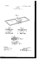
- Figure 1 is a perspective view showing the relative arrangement of the coupling and the links, the coupling being illustrated with its constituent elements assembled and engaged in looking union.
- Fig. 2 is a top plan view of the coupling, in which the elements are assembled, but not engaged in locking union.
- Fig. 3 is a view similar to Fig. 2, in which the elements are engaged in locking union.
- Fig. 4 is a vertical section of the coupling, and
- Fig. 5 is a perspective view of one of the elements, which for the purpose of convenience shall be hereinafter designated the block.
- A designates any pair of adjacent links which are united by a coupling B.
- the links are loosely connected by said coupling, so that the latter will serve to take up any rolling action on the part of the former in the movement of the chain.
- the coupling B is of two-part construction and embodies a body portion 1 and a block 2, fitting in said body portion and adapted to be engaged therewith in looking union.
- the block 2 is of peculiar contour and fits in a recess or cut-away portion of corresponding contour in the body portion 1.
- the said block is substantially T-shaped, as shown in I Fig. 5, and is formed with a central longitudinal portion 3, which is raised above the level ofthe portions of the block disposed on each side thereof, this raised portion Sbeing adapted to lie flush with the face of the body portion.
- the portion 3 is formed adjacent each of the side portions 4 with shoulders 5, which lie at right angles to the side portions 4, the latter having their inner ends formed with angular cut away portions adjacent the raised portion 3, so as to provide projecting shoulders 6, one for each ofthe side portions 4 and disposed on each side of the raised portion 3.
- the raised portion 3 adjacent its inner end is formed on each side with inclined surfaces 7, between which is a longitudinal recess or slot 8, which divides the inner end of the raised portion 3 into bifurcations, each of the latter terminating in an enlarged head or shoulder 9.
- the side portions 4 have their outer edges beveled or formed with a curve corresponding to the curvature of the body portion 1, as at 10, the said beveled faces 10 lying flush with the periphery of the body portion 1.
- the block On its underneath surface the block is provided with parallel spaced longitudinal grooves 11, extending beneath the side portions 4 and having a rib 12 disposed therebetween.
- the body portion 1 is provided with an enlarged central opening 13, which is formed with a longitudinal rib 14 and adjacent said rib with curved walls 15, against which the sides of the links A rest and have a rolling movement.
- the curved walls 15 continue until they meet the grooves 11 of the block 2, a
- the said grooves possessing a curvature of approximately the same degree as the curvature of the inner wall 15 of the body portion 1.
- the ribs 12 and 14 upon the block 2 and body portion 1, respectively, coact to prevent the adjacent portions of the links from frictionally engaging one another and retarding the action or movement of the chain.
- the upper face of the portion 1 is cut away its entire length, as at 16, so as to provide a space through which the raised portion 3 of the block 2 extends, and the sides of the body portion 1 are cut away, as at 17, and formed with angular recesses of corresponding contour to the shoulder 6 upon the block 2, the side portions 4 of the said block being received in the cut-away portions 17 of the body portion of the coupling.
- the block 2 is slid into the recess 16 in the body portion, the side portions 4 of the said block entering the recesses 17, of corresponding contour, until the said block has reached the limit of its travel,the outer face 18 thereof lying flu sh with the outer face of the body portion 1 and the enlarged heads 9 on the bifurcated inner end thereof projecting slightly beyond the adjacent face of the body portion 1.
- the block 2 is non-resilient, so that it is necessary to use a suitable tool, such as a Wedge, for spreading the bifurcated inner ends of the block 2 apart, as shown in Fig. 3, so that the enlarged heads or shoulders 9 thereof will confront the adjacent face of the body portion 1 and prevent the displacement of the block 2 therefrom.
- a suitable tool such as a Wedge
- the wedge is inserted into the slot 8 and driven home until the ends 9 are spread apart, at which time the inclined portlons 7 will lie in a straight line with the sides of the shoulders 5 upon the raised portion 3.
- the metal employed may be of such temper that the bifurcations formed upon the end of the block 2 will tend to spread apart through their own resiliency, thereby eliminatin the necessity of using extraneous means for forcing the said ends apart.
- a coupling for chainlinks comprising an elongated body portion slotted throughout its ength on one face, and having recesses to receive the chain-links, and a block fitting in the slotted face of said body with its outer face flush with the outer face of the body, and means carried by said block when engaging the body for securing the block in engagement with the body.
- a coupling for chain-links comprising a body slotted throughout its length on one face, and having recesses to receive the chainlinks, said body also having cut-away portions at one end, and a block fitting in the slotted face of the body and having side portions fitting in the recesses in the end of the body and means for securing said block in locked engagement in the body.
- a coupling for chain-links comprising a body slotted throughout its length on one face, and having interior recesses, and having recesses in one end, a block fitting in the slotted face of said body and having side portions fitting in the end recesses of the body, the underneath face of said block having longitudinal recesses registering with the chainreceiving recesses of the body, and means for securing the block in locked engagement with the body.
- connection therefor embodying a body portion and a locking element, said body ortion being formed with a recess corresponding in shape to said locking element, said locking element being seated in said recess, and having its outer surfaces lying flush with the periphery of the body portion, the ends of said locking element be ing split and adapted to be spread apart into locking engagement with said body portion.
- a coupling therefor embodying a body portion formed with a central bore, and a T-shaped opening, and a T-shaped locking element carried by said body portion and interfitting in said T-s'haped opening, said locking element having its end formed with furcations adapted to be spread apart into locking engagement with the body portion.
- connection therefor embodying a body portion formed with a central bore and a .T-shaped opening, and a T- shaped locking element interfitting in said opening and provided with a bifurcated end terminating 1n enlarged shoulders, adapted to be spread apart into locking engagement with said body portion.
Landscapes
- Engineering & Computer Science (AREA)
- General Engineering & Computer Science (AREA)
- Mechanical Engineering (AREA)
- Devices For Conveying Motion By Means Of Endless Flexible Members (AREA)
Description
N0. 809,113. PATENTEDJAN. 2, 1906.
J. M. JOYCE. CHAIN,
APPLICATION FILED JUNE'IZ, 1905- I attozwelgs A 1/9 0 as I amvemtoz UNITED STATES PATENT OFFICE.
CHAIN.
Specification of Letters Patent.
Patented Jan. 2, 1906.
Application filed June 12, 1905. Serial No. 264,910.
zen of the United States of America, residing at Edgerton, in the county of Rock and State of Wisconsin, have invented certain new and useful Improvements in Chains, of which the following is a specification, reference being had therein to the accompanying drawings.
My invention relates to certain new and useful improvements in detachable links for chains, and more especially to that portion of the chain known as the coupling, which is used to connect each pair of adjacent links and which takes up the rolling action of each link in the movement of the chain.
The invention consists, primarily, in a coupling of two-part construction in which interfitting elements are employed which are engaged in looking union either by the use of some extraneous means, such as a suitable tool or wedge, or through the resiliency of one of the elements. v
The detailed construction will appear as the description proceeds, in which reference is had to the accompanying drawings, forming a part of this specification, like characters designating like parts throughout the several views, in which Figure 1 is a perspective view showing the relative arrangement of the coupling and the links, the coupling being illustrated with its constituent elements assembled and engaged in looking union. Fig. 2 is a top plan view of the coupling, in which the elements are assembled, but not engaged in locking union. Fig. 3 is a view similar to Fig. 2, in which the elements are engaged in locking union. Fig. 4 is a vertical section of the coupling, and Fig. 5 is a perspective view of one of the elements, which for the purpose of convenience shall be hereinafter designated the block.
Referring to the accompanying drawings, A designates any pair of adjacent links which are united by a coupling B. The links are loosely connected by said coupling, so that the latter will serve to take up any rolling action on the part of the former in the movement of the chain.
The coupling B is of two-part construction and embodies a body portion 1 and a block 2, fitting in said body portion and adapted to be engaged therewith in looking union. The block 2 is of peculiar contour and fits in a recess or cut-away portion of corresponding contour in the body portion 1. The said block is substantially T-shaped, as shown in I Fig. 5, and is formed with a central longitudinal portion 3, which is raised above the level ofthe portions of the block disposed on each side thereof, this raised portion Sbeing adapted to lie flush with the face of the body portion. The portion 3 is formed adjacent each of the side portions 4 with shoulders 5, which lie at right angles to the side portions 4, the latter having their inner ends formed with angular cut away portions adjacent the raised portion 3, so as to provide projecting shoulders 6, one for each ofthe side portions 4 and disposed on each side of the raised portion 3. The raised portion 3 adjacent its inner end is formed on each side with inclined surfaces 7, between which is a longitudinal recess or slot 8, which divides the inner end of the raised portion 3 into bifurcations, each of the latter terminating in an enlarged head or shoulder 9. The side portions 4 have their outer edges beveled or formed with a curve corresponding to the curvature of the body portion 1, as at 10, the said beveled faces 10 lying flush with the periphery of the body portion 1. On its underneath surface the block is provided with parallel spaced longitudinal grooves 11, extending beneath the side portions 4 and having a rib 12 disposed therebetween.
The body portion 1 is provided with an enlarged central opening 13, which is formed with a longitudinal rib 14 and adjacent said rib with curved walls 15, against which the sides of the links A rest and have a rolling movement. The curved walls 15 continue until they meet the grooves 11 of the block 2, a
the said grooves possessing a curvature of approximately the same degree as the curvature of the inner wall 15 of the body portion 1. The ribs 12 and 14 upon the block 2 and body portion 1, respectively, coact to prevent the adjacent portions of the links from frictionally engaging one another and retarding the action or movement of the chain. The upper face of the portion 1 is cut away its entire length, as at 16, so as to provide a space through which the raised portion 3 of the block 2 extends, and the sides of the body portion 1 are cut away, as at 17, and formed with angular recesses of corresponding contour to the shoulder 6 upon the block 2, the side portions 4 of the said block being received in the cut-away portions 17 of the body portion of the coupling.
In practical use the block 2 is slid into the recess 16 in the body portion, the side portions 4 of the said block entering the recesses 17, of corresponding contour, until the said block has reached the limit of its travel,the outer face 18 thereof lying flu sh with the outer face of the body portion 1 and the enlarged heads 9 on the bifurcated inner end thereof projecting slightly beyond the adjacent face of the body portion 1.
In the preferred embodiment of my invention the block 2 is non-resilient, so that it is necessary to use a suitable tool, such as a Wedge, for spreading the bifurcated inner ends of the block 2 apart, as shown in Fig. 3, so that the enlarged heads or shoulders 9 thereof will confront the adjacent face of the body portion 1 and prevent the displacement of the block 2 therefrom. In this construction the wedge is inserted into the slot 8 and driven home until the ends 9 are spread apart, at which time the inclined portlons 7 will lie in a straight line with the sides of the shoulders 5 upon the raised portion 3.
Obviously the metal employed may be of such temper that the bifurcations formed upon the end of the block 2 will tend to spread apart through their own resiliency, thereby eliminatin the necessity of using extraneous means for forcing the said ends apart.
It is obvious that the construction above described affords a detachable link connection which is inexpensive to manufacture and in which the constituent elements are easily and quickly assembled and effectually locked from displacement.
Having fully described my invention, I claim- 1. A coupling for chainlinks, comprising an elongated body portion slotted throughout its ength on one face, and having recesses to receive the chain-links, and a block fitting in the slotted face of said body with its outer face flush with the outer face of the body, and means carried by said block when engaging the body for securing the block in engagement with the body.
2. A coupling for chain-links, comprising a body slotted throughout its length on one face, and having recesses to receive the chainlinks, said body also having cut-away portions at one end, and a block fitting in the slotted face of the body and having side portions fitting in the recesses in the end of the body and means for securing said block in locked engagement in the body.
3. A coupling for chain-links, comprising a body slotted throughout its length on one face, and having interior recesses, and having recesses in one end, a block fitting in the slotted face of said body and having side portions fitting in the end recesses of the body, the underneath face of said block having longitudinal recesses registering with the chainreceiving recesses of the body, and means for securing the block in locked engagement with the body.
4. In combination with a pair of adjacent chain-links, a connection therefor, embodying a body portion and a locking element, said body ortion being formed with a recess corresponding in shape to said locking element, said locking element being seated in said recess, and having its outer surfaces lying flush with the periphery of the body portion, the ends of said locking element be ing split and adapted to be spread apart into locking engagement with said body portion.
5. In combination with a pair of adjacent chain-links, a coupling therefor, embodying a body portion formed with a central bore, and a T-shaped opening, and a T-shaped locking element carried by said body portion and interfitting in said T-s'haped opening, said locking element having its end formed with furcations adapted to be spread apart into locking engagement with the body portion.
6. In combination with a pair of adjacent chain-links, a connection therefor, embodying a body portion formed with a central bore and a .T-shaped opening, and a T- shaped locking element interfitting in said opening and provided with a bifurcated end terminating 1n enlarged shoulders, adapted to be spread apart into locking engagement with said body portion.
7. In combination with a pair of adjacent chain-links, and connection therefor, embodying a body portion formed with a central bore, and a T-shaped opening, and a T- shaped locking element carried by said body portion and interfitting in said opening, said locking element being formed adjacent its end with a split portion adapted to be spread apart into locking engagement with said body portion.
In testimony whereof I a'fi'iX my signature in the presence of two witnesses.
JAMES M. J OYOE.
Witnesses:
E. M. LADD, J. L. HOLTON.
Priority Applications (1)
| Application Number | Priority Date | Filing Date | Title |
|---|---|---|---|
| US26491005A US809113A (en) | 1905-06-12 | 1905-06-12 | Chain. |
Applications Claiming Priority (1)
| Application Number | Priority Date | Filing Date | Title |
|---|---|---|---|
| US26491005A US809113A (en) | 1905-06-12 | 1905-06-12 | Chain. |
Publications (1)
| Publication Number | Publication Date |
|---|---|
| US809113A true US809113A (en) | 1906-01-02 |
Family
ID=2877594
Family Applications (1)
| Application Number | Title | Priority Date | Filing Date |
|---|---|---|---|
| US26491005A Expired - Lifetime US809113A (en) | 1905-06-12 | 1905-06-12 | Chain. |
Country Status (1)
| Country | Link |
|---|---|
| US (1) | US809113A (en) |
-
1905
- 1905-06-12 US US26491005A patent/US809113A/en not_active Expired - Lifetime
Similar Documents
| Publication | Publication Date | Title |
|---|---|---|
| US809113A (en) | Chain. | |
| US975323A (en) | Chain-coupling. | |
| US935253A (en) | Pick. | |
| US1427229A (en) | Conveyer cleat | |
| US1186774A (en) | Conveyer-chain cleat. | |
| US921245A (en) | Rail-joint. | |
| US1228386A (en) | Rail-joint. | |
| US1053599A (en) | Claw-bar. | |
| US1297065A (en) | Pick. | |
| US1163962A (en) | Spike. | |
| US1179214A (en) | Rail-joint. | |
| US1148841A (en) | Rail-joint. | |
| US885787A (en) | Railway-rail joint. | |
| US688735A (en) | Chain-link. | |
| US1005529A (en) | Rail-joint. | |
| US1061037A (en) | Compound rail. | |
| US1007257A (en) | Rail-joint. | |
| US1130581A (en) | Chain. | |
| US760357A (en) | Rail-joint. | |
| US1439191A (en) | Safety rail joint | |
| US898917A (en) | Rail-joint. | |
| US1309356A (en) | Planoqrapii co | |
| US741139A (en) | Rail-joint. | |
| US1205580A (en) | Bolt or railroad-spike. | |
| US1002498A (en) | Rail-shoe. |