US809109A - Cotton-chopper. - Google Patents
Cotton-chopper. Download PDFInfo
- Publication number
- US809109A US809109A US24890005A US1905248900A US809109A US 809109 A US809109 A US 809109A US 24890005 A US24890005 A US 24890005A US 1905248900 A US1905248900 A US 1905248900A US 809109 A US809109 A US 809109A
- Authority
- US
- United States
- Prior art keywords
- disks
- bars
- shafts
- cutting
- chopper
- Prior art date
- Legal status (The legal status is an assumption and is not a legal conclusion. Google has not performed a legal analysis and makes no representation as to the accuracy of the status listed.)
- Expired - Lifetime
Links
- 239000000463 material Substances 0.000 description 2
- 238000010008 shearing Methods 0.000 description 2
- 229920000742 Cotton Polymers 0.000 description 1
- 239000002184 metal Substances 0.000 description 1
Images
Classifications
-
- A—HUMAN NECESSITIES
- A01—AGRICULTURE; FORESTRY; ANIMAL HUSBANDRY; HUNTING; TRAPPING; FISHING
- A01B—SOIL WORKING IN AGRICULTURE OR FORESTRY; PARTS, DETAILS, OR ACCESSORIES OF AGRICULTURAL MACHINES OR IMPLEMENTS, IN GENERAL
- A01B1/00—Hand tools
- A01B1/06—Hoes; Hand cultivators
Definitions
- the invention relates to an improved cotton-chopper particularly constructed and arranged for the effective thinning out of standing cotton-stalks.
- the invention consists mainly in a cottonchopper comprising a pair of cooperating cutting-disks having interrupted or recessed cutting edges and a suitable framework for properly bracing and supporting said disks during operation.
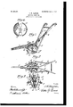
- FIG. 1 is a perspective view of a cottonchopper constructed in accordance with my invention.
- Fig. 2 is a plan of the same.
- Fig. 3 is a transverse section of the chopper.
- Fig. 4 is a view in elevation of one of the cutting-disks.
- my improved cotton-chopper comprises a draftbeam 1, to the rear end of which is secured the usual divergent handle-bars 2, having the ordinary hand-grips 3 at their free ends.
- each brace-bar is connected with the lower end of a supporting-bar 5, which bars extend upwardly toward and are directly connected to the handles 2, preferably by a removable connection 6, arranged to permit adjustment when desired.
- each brace-bar is provided with a journal or bearing 7, the bearings of the respective brace-bars being arranged in alinement transverse to the length of the draft-beam, whereby to properly position the shafts supported by said bearings.
- shafts 10 are 'mounted in the respective pairs of bearings 7 and 9, one shaft extending each side of beam 1.
- shafts v10 incline downward and forward from the brace-beam.
- the inner or meeting ends of shafts 10 are respectively provided with a bevel-gear 11, arranged to intermesh and serving to secure uniformity and regularity in the revolution of the. cutting-disks.
- Gutter-disks 1 2 are supported by the framework described, one on each shaft 10.
- the disks are preferably of thin metal and di shed, being provided with iived bearing-collars 13, carrying set-screws 14, by which the disks a may be adjustably secured on the shafts.
- the peripheries of the disks are sharpened t0 provide cutting edges 15, and this cutting edge is interrupted by forming radial recesses 16 in the disks, extending to the edge thereof, as shown.
- the disks 12 are secured on the shafts 10 so that the recesses of one disk register in transverse alinement with the recesses of the other disk. Owing to the inclination of the shafts 10, the disks 12, which are of course at right angles to said shafts, will also incline from the vertical, the disks being so adjusted lengthwise the shafts as to insure contact of the respective cutting edges 15 at the eXtreme lowest point of travel of said cutting edges, thereby providing and maintaining a shearing junction of the cutting edges at the point of the disks in contact with the ground.
- the forward incline of the cutter-shafts is a material feature of the invention and tends to prevent undue strain on the cutting-disks during operation, for by reason of this ineline the rear edges of the disks are at all times more separated than the front edges.
- the frame for the disks including the braeebars 4, the supporting bars 5, and the hanger-strap 8, provides a simple and ellieient support for the disks and one in which any part may be readily and conveniently renewed without inconvenience or material loss of time.
- a cotton-chopper comprising a draftbeam and handle-bars connected thereto, brace-bars connected to the beam and eX- tending downwardly and rearwardly therefrom, supporting-bars adjustably connected to the handle-bars and to the brace-bars, shafts supported at their outer ends in said brace-bars, a cutting-disk fixed on each of said shafts, and means depending from the beam to support the inner ends of said shafts.
Landscapes
- Life Sciences & Earth Sciences (AREA)
- Engineering & Computer Science (AREA)
- Mechanical Engineering (AREA)
- Soil Sciences (AREA)
- Environmental Sciences (AREA)
- Harvester Elements (AREA)
Description
No. 809,109. PATENTBD JAN. 2, 1906; J. W. HAYNIE.
COTTON SHOPPER.
APPLICATION FILED MAR?, 1905.
UNITED STATESv PATENT OFFIOE.
ooTToN-CHOPPER.
Specicaton of Letters Patent.
I Patented Jan. 2, 1906.
Application led March 7J 1905. Serial No. 248,900.
Be it known that I, JAMES W. HAYNIE, a citizen of the United States, residing at Fairburn, in the county of Campbell and State of Georgia, have invented new and useful Improvements in Cotton-Oh oppers, of which the following is a speciiication.
The invention relates to an improved cotton-chopper particularly constructed and arranged for the effective thinning out of standing cotton-stalks.
The invention consists mainly in a cottonchopper comprising a pair of cooperating cutting-disks having interrupted or recessed cutting edges and a suitable framework for properly bracing and supporting said disks during operation.
The invention in its preferred embodiment of details will be described in the following specification, reference being had to the accompanying drawings, in which- Figure 1 is a perspective view of a cottonchopper constructed in accordance with my invention. Fig. 2 is a plan of the same. Fig. 3 is a transverse section of the chopper. Fig. 4 is a view in elevation of one of the cutting-disks.
Referring particularly to the drawings, my improved cotton-chopper comprises a draftbeam 1, to the rear end of which is secured the usual divergent handle-bars 2, having the ordinary hand-grips 3 at their free ends.
To provide a simple and efficient framework for directly supporting the cuttingdisks, I secure brace-bars 4 to the'bearn 1, one on each side thereof, and extend said bars rearward and downward and preferably divergent from their point of connection with the beam. The rear end of each brace-bar is connected with the lower end of a supporting-bar 5, which bars extend upwardly toward and are directly connected to the handles 2, preferably by a removable connection 6, arranged to permit adjustment when desired. Forward of its connection with the supporting-bar each brace-bar is provided with a journal or bearing 7, the bearings of the respective brace-bars being arranged in alinement transverse to the length of the draft-beam, whereby to properly position the shafts supported by said bearings.
8 represents hanger-straps, one on each side of the draft-beam and secured thereto at the upper ends. The hanger-straps are secured to the beam slightly in rear of a line joining the bearings 7 and are less in length than the vertical distance between the beam and bearings 7. The lower ends of the straps 8 are provided with bearings 9 of any suitable character. Shafts 10 are 'mounted in the respective pairs of bearings 7 and 9, one shaft extending each side of beam 1. By reason of the respective lengths and positions of brace-bars 4 and hanger-straps 8 shafts v10 incline downward and forward from the brace-beam. The inner or meeting ends of shafts 10 are respectively provided with a bevel-gear 11, arranged to intermesh and serving to secure uniformity and regularity in the revolution of the. cutting-disks.
Gutter-disks 1 2 are supported by the framework described, one on each shaft 10. The disks are preferably of thin metal and di shed, being provided with iived bearing-collars 13, carrying set-screws 14, by which the disks a may be adjustably secured on the shafts.
The peripheries of the disks are sharpened t0 provide cutting edges 15, and this cutting edge is interrupted by forming radial recesses 16 in the disks, extending to the edge thereof, as shown. The disks 12 are secured on the shafts 10 so that the recesses of one disk register in transverse alinement with the recesses of the other disk. Owing to the inclination of the shafts 10, the disks 12, which are of course at right angles to said shafts, will also incline from the vertical, the disks being so adjusted lengthwise the shafts as to insure contact of the respective cutting edges 15 at the eXtreme lowest point of travel of said cutting edges, thereby providing and maintaining a shearing junction of the cutting edges at the point of the disks in contact with the ground.
The operation will be fully apparent from the foregoing, it being understood that as the chopper is drawn forward through the cottonstalks the cutting edges will sever all stalks passing between the disks, and this cutting will continue until a registering pair of recesses 16 reaches the shearing junction of the disks, when the junction of the cutting edges will be interrupted, and the stalks durin the interruption of the cutting action wi l beleft standing.
The forward incline of the cutter-shafts is a material feature of the invention and tends to prevent undue strain on the cutting-disks during operation, for by reason of this ineline the rear edges of the disks are at all times more separated than the front edges.
IIO
The frame for the disks, including the braeebars 4, the supporting bars 5, and the hanger-strap 8, provides a simple and ellieient support for the disks and one in which any part may be readily and conveniently renewed without inconvenience or material loss of time.
Though I have shown but two recesses 16 in each cutting-disk, it is to be understood neeted to the handle-bars and to the ends of the brace-bars, and hanger-straps depending from the beam, shafts supported in the hanger-straps and brace-bars, said shafts inelining downwardly and forwardly from the beam, and a cutting-disk fixed on each of said shafts.
2. A cotton-chopper comprising a draftbeam and handle-bars connected thereto, brace-bars connected to the beam and eX- tending downwardly and rearwardly therefrom, supporting-bars adjustably connected to the handle-bars and to the brace-bars, shafts supported at their outer ends in said brace-bars, a cutting-disk fixed on each of said shafts, and means depending from the beam to support the inner ends of said shafts.
In testimony whereof I a'flix my signature in presence of two witnesses,
JAMES W. HAYNIE.
Witnesses:
C. R. HARVEY, G. J. I-IEAnN.
Priority Applications (1)
| Application Number | Priority Date | Filing Date | Title |
|---|---|---|---|
| US24890005A US809109A (en) | 1905-03-07 | 1905-03-07 | Cotton-chopper. |
Applications Claiming Priority (1)
| Application Number | Priority Date | Filing Date | Title |
|---|---|---|---|
| US24890005A US809109A (en) | 1905-03-07 | 1905-03-07 | Cotton-chopper. |
Publications (1)
| Publication Number | Publication Date |
|---|---|
| US809109A true US809109A (en) | 1906-01-02 |
Family
ID=2877590
Family Applications (1)
| Application Number | Title | Priority Date | Filing Date |
|---|---|---|---|
| US24890005A Expired - Lifetime US809109A (en) | 1905-03-07 | 1905-03-07 | Cotton-chopper. |
Country Status (1)
| Country | Link |
|---|---|
| US (1) | US809109A (en) |
Cited By (1)
| Publication number | Priority date | Publication date | Assignee | Title |
|---|---|---|---|---|
| USD273656S (en) | 1981-06-05 | 1984-05-01 | Dellinger Henry P | Rotary cultivating tool |
-
1905
- 1905-03-07 US US24890005A patent/US809109A/en not_active Expired - Lifetime
Cited By (1)
| Publication number | Priority date | Publication date | Assignee | Title |
|---|---|---|---|---|
| USD273656S (en) | 1981-06-05 | 1984-05-01 | Dellinger Henry P | Rotary cultivating tool |
Similar Documents
| Publication | Publication Date | Title |
|---|---|---|
| US809109A (en) | Cotton-chopper. | |
| US732623A (en) | Stalk-cutter and crusher. | |
| US932785A (en) | Farming implement. | |
| US100128A (en) | Improvement in combined cotton chopper and cultivator | |
| US620046A (en) | Cultivator | |
| US336811A (en) | Assigkoe to emeeson | |
| US810811A (en) | Cotton-chopper. | |
| US141903A (en) | Improvement in potato-diggers | |
| US794696A (en) | Cotton-cultivator. | |
| US884258A (en) | Weed-cutter and cultivator. | |
| US100743A (en) | Improvement in plows | |
| US818876A (en) | Stalk-cutter. | |
| US667733A (en) | Cotton-chopper. | |
| US127677A (en) | Improvement in disks for agricultural implements | |
| US281577A (en) | Lewis b | |
| US534471A (en) | Egbert feanken | |
| US310416A (en) | Combined cotton chopper and cultivator | |
| US781790A (en) | Cotton-chopper. | |
| US1122033A (en) | Plow. | |
| US158012A (en) | Improvement in combined rollers and harrows | |
| US590694A (en) | Cultivator | |
| US111391A (en) | Improvement in cultivator-plows | |
| US829556A (en) | Cotton chopper and cultivator. | |
| US754284A (en) | Beet blocker and cultivator. | |
| US210073A (en) | Improvement in cultivators |