US809108A - Apparatus for detaching the heads from the bodies of sheet-metal cans. - Google Patents
Apparatus for detaching the heads from the bodies of sheet-metal cans. Download PDFInfo
- Publication number
- US809108A US809108A US16823503A US1903168235A US809108A US 809108 A US809108 A US 809108A US 16823503 A US16823503 A US 16823503A US 1903168235 A US1903168235 A US 1903168235A US 809108 A US809108 A US 809108A
- Authority
- US
- United States
- Prior art keywords
- heads
- detaching
- bodies
- cans
- sheet
- Prior art date
- Legal status (The legal status is an assumption and is not a legal conclusion. Google has not performed a legal analysis and makes no representation as to the accuracy of the status listed.)
- Expired - Lifetime
Links
Images

Classifications
-
- B—PERFORMING OPERATIONS; TRANSPORTING
- B25—HAND TOOLS; PORTABLE POWER-DRIVEN TOOLS; MANIPULATORS
- B25B—TOOLS OR BENCH DEVICES NOT OTHERWISE PROVIDED FOR, FOR FASTENING, CONNECTING, DISENGAGING, OR HOLDING
- B25B27/00—Hand tools, specially adapted for fitting together or separating parts or objects whether or not involving some deformation, not otherwise provided for
-
- B—PERFORMING OPERATIONS; TRANSPORTING
- B23—MACHINE TOOLS; METAL-WORKING NOT OTHERWISE PROVIDED FOR
- B23K—SOLDERING OR UNSOLDERING; WELDING; CLADDING OR PLATING BY SOLDERING OR WELDING; CUTTING BY APPLYING HEAT LOCALLY, e.g. FLAME CUTTING; WORKING BY LASER BEAM
- B23K1/00—Soldering, e.g. brazing, or unsoldering
- B23K1/018—Unsoldering; Removal of melted solder or other residues
-
- Y—GENERAL TAGGING OF NEW TECHNOLOGICAL DEVELOPMENTS; GENERAL TAGGING OF CROSS-SECTIONAL TECHNOLOGIES SPANNING OVER SEVERAL SECTIONS OF THE IPC; TECHNICAL SUBJECTS COVERED BY FORMER USPC CROSS-REFERENCE ART COLLECTIONS [XRACs] AND DIGESTS
- Y10—TECHNICAL SUBJECTS COVERED BY FORMER USPC
- Y10T—TECHNICAL SUBJECTS COVERED BY FORMER US CLASSIFICATION
- Y10T29/00—Metal working
- Y10T29/49—Method of mechanical manufacture
- Y10T29/49815—Disassembling
Definitions
- the first step consists in the removal of the heads from the bodies; and the present invention consists in an apparatus comprising appliances whereby heat is com- Inunicated to the heads of the cans to melt the solder which holds them to the body and also in means for detaching the loosened heads, as will hereinafter fully appear.
- FIG. 2 is a top or plan view of Fig. 1.
- Fig. 3 is an end view of Fig. 1 looking in the direction indicated by the arrow in that figure.
- Figs. 4 and 5 are enlarged views of parts of the apparatus.
- Fig. 6 is a section of either Fig. 4 or Fig. 5 taken on line A A, except that certain parts shown in those figures are omitted, and looking in 1 the direction indicated by the arrows.
- 1 and 2 are respectively the front and rear end frame.
- the two sections of each frame are united by the transverse bar 3 and bolts 4, and the two composite frames are connected by anglebars 7, which are secured side by side to the transverse bars 3 and together form a track or way and a support for an endless sprocketchain 9, hereinafter more particularly referred to.
- l0 and 11 are shafts, the former being the driver, supported rotatably in suitable bearings in the frames 1 and 2. These shafts are provided with tight sprocket wheels 13, which carry the endless sprocket-chain 9, before referred to.
- 14 14 are segmental or open carriers for the cans fastened at suitable and uniform disform heating-burners 22, the flames from which are situated at each side of the apparatus, and arranged in a horizontal plane, and play upon the can-heads and liquefy the solder in the circular joints.
- the burners described are thought to be .the path of the upper limb or edge of the canheads. They are supported in an angular or, flaring position as seen from the top, and the distance across their ends, with which the cans first come in contact, is less than the distance between the flanges of the can-heads, while their other ends are separated to a much greater distance.
- the vertical position of these head-detaching blades is such that they bear forcibly upon the can-bodies as they are carried under them for a purpose hereinafter described.
- head-detaching blades To admit of the head-detaching blades being adapted to suit cans of different diameters and lengths, they are, bypreference, provided with hubs 25, which are slid over rods 27 and held in place by means of set-screws 29, and the ends of the said rods pass throu h vertical slots 30 in the frame 1 and are he (1 by nuts 31.
- the head-detaching blades 23 will in most cases be sufficient to dislodge the can-heads; but to insure their dislodgment I provide the apparatus with the lower headdetaching blades 33, which are held b the transverse bar 3 of the frame 1 in angu ar or flarin positions like the ones 23 and situated direct y beneath them, so that the two sets of blades will coo erate inremoving the heads from the can-b0 ies.
- These latter blades require only lateral adjustment, and this is effected by passing their holding-bolts through slots in the bar 3, as shown by the dotted lines in Fig. 3.
- the upper surface of the lower head detaching blade is elevated slightly above the path of the lower portion of the can-bodies, and the distance between the upper and lower blades is therefore less than the diameter of the can-bodies,which in passing between them are distorted from a cylindrical form. This distortion Will in many instances be sufficient to spring off the heads without the head-spreading effect of the blades.
- 35 and 35 are flared plates secured, preferably, to the blades 23 to center the cans as they approach the head-detaching devices. In other words, they insure the passage of the detaching-blades between the flanges of the heads.
- the operation of the apparatus is as follows: The operator, who stands at the rear end of the machine,places the cans (denoted by :10) in the segmental holders, which carry them in a fixed positionthat is to say, without rotationb etween the heaters, which liquefy the solder in the circular seams. Before the liquefied solder cools the cans are conveyed to the head detaching devices, which compress the bodies and push off the heads, the angular blades entering between the flanges of the heads, and the detached heads fall at the sides of the machine. The bodies are delivered at the front end of the machine. To concentrate the heat from the burners upon the cans and protect persons standing at the sides of the machine, it may be advantageous to provide the apparatus with a hood 39. (Shown only in dotted delineation in Fig. 1..)
Landscapes
- Engineering & Computer Science (AREA)
- Mechanical Engineering (AREA)
- Electric Connection Of Electric Components To Printed Circuits (AREA)
Description
L A 6T E M T E B NH S P D0 E TD Q NT) ED O B E H T M 0 HE F El R DN AA KE E H T G N I H G A T E D R 0 P Am T A R mm P A APPLICATION FILED AUG. 4.1903.
2 SHEETS-SHEET 1.
PATENTED JAN. 2, 1906. APPARATUS FOR DETAGHING THE HEADS FROM THE BODIES 0F SHEET METAL SJK. GREEN.
CANS. APPLICATION FILED AUG. 4,1903.
2 SHEETSSHEET 2.
attozmqo UNITED STATES PATENT OFFICE.
STANLEY K. GREEN, OF BALTIMORE, MARYLAND.
APPARATUS FOR DETACHING THE HEADS FROM THE BODIES 0F SHEET-METAL CANS.
Specification of Letters Patent.
Patented Jan. 2, 1906.
To aZZ whom it 11mg concern:
Be it known that I, STANLEY K. GREEN, of the city of Baltimore and State of Maryland, have invented certain Improvements in Apparatus for Detaching' the Heads from the Bodies of Sheet-Metal Cans, of which the following is a specification.
In the utilization of waste tin-plate cans or those which have been emptied of their contents the first step consists in the removal of the heads from the bodies; and the present invention consists in an apparatus comprising appliances whereby heat is com- Inunicated to the heads of the cans to melt the solder which holds them to the body and also in means for detaching the loosened heads, as will hereinafter fully appear.
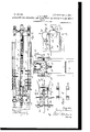
In the further description of the said invlention which follogvs referenfce is made to t e accom anying rawings, orming a art hereof, and in which p Figure 1 is. an exterior side elevation of the improved apparatus. Fig. 2 is a top or plan view of Fig. 1. Fig. 3 is an end view of Fig. 1 looking in the direction indicated by the arrow in that figure. Figs. 4 and 5 are enlarged views of parts of the apparatus. Fig. 6 is a section of either Fig. 4 or Fig. 5 taken on line A A, except that certain parts shown in those figures are omitted, and looking in 1 the direction indicated by the arrows.
Referring now to the drawings, 1 and 2 are respectively the front and rear end frame. The two sections of each frame are united by the transverse bar 3 and bolts 4, and the two composite frames are connected by anglebars 7, which are secured side by side to the transverse bars 3 and together form a track or way and a support for an endless sprocketchain 9, hereinafter more particularly referred to.
l0 and 11 are shafts, the former being the driver, supported rotatably in suitable bearings in the frames 1 and 2. These shafts are provided with tight sprocket wheels 13, which carry the endless sprocket-chain 9, before referred to.
14 14 are segmental or open carriers for the cans fastened at suitable and uniform disform heating-burners 22, the flames from which are situated at each side of the apparatus, and arranged in a horizontal plane, and play upon the can-heads and liquefy the solder in the circular joints.
The burners described are thought to be .the path of the upper limb or edge of the canheads. They are supported in an angular or, flaring position as seen from the top, and the distance across their ends, with which the cans first come in contact, is less than the distance between the flanges of the can-heads, while their other ends are separated to a much greater distance. The vertical position of these head-detaching blades is such that they bear forcibly upon the can-bodies as they are carried under them for a purpose hereinafter described.
To admit of the head-detaching blades being adapted to suit cans of different diameters and lengths, they are, bypreference, provided with hubs 25, which are slid over rods 27 and held in place by means of set-screws 29, and the ends of the said rods pass throu h vertical slots 30 in the frame 1 and are he (1 by nuts 31. The head-detaching blades 23 will in most cases be sufficient to dislodge the can-heads; but to insure their dislodgment I provide the apparatus with the lower headdetaching blades 33, which are held b the transverse bar 3 of the frame 1 in angu ar or flarin positions like the ones 23 and situated direct y beneath them, so that the two sets of blades will coo erate inremoving the heads from the can-b0 ies. These latter blades require only lateral adjustment, and this is effected by passing their holding-bolts through slots in the bar 3, as shown by the dotted lines in Fig. 3. The upper surface of the lower head detaching blade is elevated slightly above the path of the lower portion of the can-bodies, and the distance between the upper and lower blades is therefore less than the diameter of the can-bodies,which in passing between them are distorted from a cylindrical form. This distortion Will in many instances be sufficient to spring off the heads without the head-spreading effect of the blades.
35 and 35 are flared plates secured, preferably, to the blades 23 to center the cans as they approach the head-detaching devices. In other words, they insure the passage of the detaching-blades between the flanges of the heads.
37 is a curved spring-holdcr with one end thereof secured in any suitable manner to the front frame 1 and with its other end adapted to bear with a spring-pressure on the canbodies as they traverse the head-detaching devices.
The operation of the apparatus is as follows: The operator, who stands at the rear end of the machine,places the cans (denoted by :10) in the segmental holders, which carry them in a fixed positionthat is to say, without rotationb etween the heaters, which liquefy the solder in the circular seams. Before the liquefied solder cools the cans are conveyed to the head detaching devices, which compress the bodies and push off the heads, the angular blades entering between the flanges of the heads, and the detached heads fall at the sides of the machine. The bodies are delivered at the front end of the machine. To concentrate the heat from the burners upon the cans and protect persons standing at the sides of the machine, it may be advantageous to provide the apparatus with a hood 39. (Shown only in dotted delineation in Fig. 1..)
I claim as my invention 1. In an apparatus for detaching the heads from the bodies of soldered sheet-metal cans, the combination of heaters, mechanism to convey the cans between the said heaters whereby the solder in the head-joints is liquefied, and devices to separate the heads from the bodies while the said solder is in a melted condition, substantially as s ecified.
2. In an apparatus for detaching tl i e heads from the bodles of soldered sheet-metal cans, the combination of heaters, a conveyer to carry the cans to and from the said heaters, detaching devices to separate the heads from the bodies while the solder in the joint is heat ed to a liquefied condition, and a centering appliance whereby the cans are accurately presented to the head-detaching devices, substantially as specified.
3. In an apparatus for detaching the heads from the bodies of soldered sheet-metal cans, the combination of a movable endless conveyer-chain, segmental can holders or carriers attached to the said endless chain, heating appliances between which the endless chain conveys the cans, and flaring head-detaching blades which in the movement of the cans pass between the flanged heads thereof and separate them from the bodies, substantially as specified.
4. In an apparatus for detaching the heads from the bodies of soldered sheet-metal cans, the combination of a movable endless conveyer-chain carrying can-holders, a heater at each side of the said endless chain, and headdetaching appliances which comprise devices to compress the can-bodies between the heads thereof or distort them from a cylindrical form while the solder is in a liquefied condition, substantially as specified.
STANLEY K. GREEN.
Witnesses:
OREGON MILTON DENNIS, MAURICE E. CoRBIN.
Priority Applications (1)
| Application Number | Priority Date | Filing Date | Title |
|---|---|---|---|
| US16823503A US809108A (en) | 1903-08-04 | 1903-08-04 | Apparatus for detaching the heads from the bodies of sheet-metal cans. |
Applications Claiming Priority (1)
| Application Number | Priority Date | Filing Date | Title |
|---|---|---|---|
| US16823503A US809108A (en) | 1903-08-04 | 1903-08-04 | Apparatus for detaching the heads from the bodies of sheet-metal cans. |
Publications (1)
| Publication Number | Publication Date |
|---|---|
| US809108A true US809108A (en) | 1906-01-02 |
Family
ID=2877589
Family Applications (1)
| Application Number | Title | Priority Date | Filing Date |
|---|---|---|---|
| US16823503A Expired - Lifetime US809108A (en) | 1903-08-04 | 1903-08-04 | Apparatus for detaching the heads from the bodies of sheet-metal cans. |
Country Status (1)
| Country | Link |
|---|---|
| US (1) | US809108A (en) |
-
1903
- 1903-08-04 US US16823503A patent/US809108A/en not_active Expired - Lifetime
Similar Documents
| Publication | Publication Date | Title |
|---|---|---|
| US809108A (en) | Apparatus for detaching the heads from the bodies of sheet-metal cans. | |
| US784856A (en) | Apparatus for unsoldering the joints of sheet-metal cans. | |
| US1094179A (en) | Lap-seam-body maker. | |
| US495426A (en) | Can-body-making machine | |
| US564163A (en) | Can-cooling machinery | |
| US518375A (en) | Ments | |
| US249244A (en) | Apparatus for soldering sheet-metal cans | |
| US949722A (en) | Machine for forming can-bodies. | |
| US384825A (en) | coleman | |
| USRE13007E (en) | young | |
| US521896A (en) | egberts | |
| US2132145A (en) | Apparatus for soldering ends to can bodies | |
| US776330A (en) | Feed mechanism for can-soldering machines or for other purposes. | |
| US250096A (en) | Machine for soldering side seams of cans | |
| US1107464A (en) | Galvanizing-machine. | |
| US512403A (en) | Mechanism for fluxing cans | |
| US723388A (en) | Can-soldering machine. | |
| US336659A (en) | Can-soldering machine | |
| US229546A (en) | Ohaeles e | |
| US856698A (en) | Can-soldering machine. | |
| US695521A (en) | Apparatus for side-seaming metal cans. | |
| US905268A (en) | Can fusing and soldering machine for square, rectangular, or polygonal cans. | |
| US689056A (en) | Apparatus for soldering bottoms or tops of tin cans, &c. | |
| US729261A (en) | Soldering-machine. | |
| US773800A (en) | Can-fusing machine. |