US809096A - Wire-stretcher. - Google Patents
Wire-stretcher. Download PDFInfo
- Publication number
- US809096A US809096A US26118505A US1905261185A US809096A US 809096 A US809096 A US 809096A US 26118505 A US26118505 A US 26118505A US 1905261185 A US1905261185 A US 1905261185A US 809096 A US809096 A US 809096A
- Authority
- US
- United States
- Prior art keywords
- wire
- frame
- reel
- machine
- secured
- Prior art date
- Legal status (The legal status is an assumption and is not a legal conclusion. Google has not performed a legal analysis and makes no representation as to the accuracy of the status listed.)
- Expired - Lifetime
Links
- 238000010276 construction Methods 0.000 description 3
- 238000004519 manufacturing process Methods 0.000 description 1
- 230000004048 modification Effects 0.000 description 1
- 238000012986 modification Methods 0.000 description 1
- KAICRBBQCRKMPO-UHFFFAOYSA-N phosphoric acid;pyridine-3,4-diamine Chemical compound OP(O)(O)=O.NC1=CC=NC=C1N KAICRBBQCRKMPO-UHFFFAOYSA-N 0.000 description 1
Images
Classifications
-
- A—HUMAN NECESSITIES
- A01—AGRICULTURE; FORESTRY; ANIMAL HUSBANDRY; HUNTING; TRAPPING; FISHING
- A01G—HORTICULTURE; CULTIVATION OF VEGETABLES, FLOWERS, RICE, FRUIT, VINES, HOPS OR SEAWEED; FORESTRY; WATERING
- A01G23/00—Forestry
- A01G23/02—Transplanting, uprooting, felling or delimbing trees
- A01G23/06—Uprooting or pulling up trees; Extracting or eliminating stumps
- A01G23/062—Pulling up trees or stumps
- A01G23/065—Pulling up trees or stumps in a substantially vertical plane
Definitions
- My invention relates to a combined wire stretching, tying, and splicing machine, and has for its object to provide a device of this character which is simple in its construction, easy and cheap to manufacture, strong, durable, and efficient.
- my invention consists in the novel construction providing for stretching, tying, and splicing wires, as Will be hereinafter fully described.
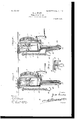
- Figure l is a perspective view showing machine in act of tying a broken wire.
- Fig. 2 is asimilar view showing machine in act of taking slack out of a wire.
- top 8 of frame 2 is cut out and two rollers 9 are suitably secured therein, while a removable roller 10 is secured in the center of the top of the frame between the two rollers 9 by means of a pin or thumbscrew 11.
- 15 indicates a chain secured to the side of the-frame 2 and carrying a hook 16 at the end thereof, and 17 is a pawl carried on the frame 2, designed to engage the pinion 6 to lock the same against rotation.
- the crank is then reversed, unwinding the ends of the wire from the reel 4, and the ends of the wire are then wrapped around the wire on each side of the tie, which produces a strong and durable Wire-knot.
- the machine is laced as shown in Fig. 2, the small removab e roller 10 isremoved, and a short piece of wire 21 is passed over the wire, and the ends are secured around the small hooks or lugs 12 on the reel 4.
- the crank 7 is turned, which rotates the reel 4 and winds the short wire 21 thereon, which draws the wire 14 down between the rollers 9.
- the removable roller 10 When the wire has been tightened sufliciently and the slack taken therefrom, the removable roller 10 is replaced, as shown in Fig. 1, and the machine is turned over, as before described, which ties the wire above the roller 10 and leaves a loop in the wire. The crank is then reversed, unwinding the small wire 21 from the reel 4. The removable roller 10 is again removed, which allows the loop in thewire to be disengaged from the machine, and the said loop is then cut from the wire with the wire-cutter 20 in the handle 3.
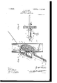
- the machine In order to stretch wire when stapling same to fenceposts, the machine is placed in position (shown in Fig. 3) against a post 22, the chain is carried around the post and is engaged by the hook 16.
- the wire is passed through the frame, as shown, and is bent over one of the hooks 12 on the reel 4.
- the crank 7 is then turned, which revolves the reel 4 and winds the wire thereon, stretching the same and
- the pawl 17 is pressed into engagement with the pinion 6, which locks the reel against rotation, and the wire is stapled to the 0st.
- the combination with a frame, of a reel carried therein and provided with means adapted to have the wire secured thereto, said frame being constructed to allow the wire to lead to said reel at substantially right angles to said reel and an element in said frame for causing the twist in said wire to occur outside of said frame.
Landscapes
- Life Sciences & Earth Sciences (AREA)
- Biodiversity & Conservation Biology (AREA)
- Ecology (AREA)
- Forests & Forestry (AREA)
- Environmental Sciences (AREA)
- Wire Processing (AREA)
Description
I; run vlioz PATENTED JAN. 2, 1906.
2 SHEBTS-SHEET 1.
Z A CURTIS WIRE STRETGHER.
APPLIGATION FILED MAY19,1905.
PATENTED JAN. 2, 1906.
. I1 mm v. B A T M R U U TI IS A N .Mm IM m P '2 SHEETS-SHEET 2.
UNITED STATES PATENT OFFICE.
WlRE-STRETCHER.
Specification-0f Letters Patent.
Patented Jan. 2, 1906.
Application filed May 19, 1905. Serial No. 261,185.
To all whom it may concern:
Be it known that I, ZENAS ALBERT CURTIS, a citizen of the United States, residing at Channing, in the county of Hartley and State of Texas, have invented certain new and useful Improvements in Wire-Stretchers; and I do declare the following to be a full, clear, and exact description of the invention, such as will enable others skilled in the art to which it appertains to make and use the same, reference being had to the accompanying drawings, and to the figures of reference marked thereon, which form a part of this specification. i
My invention relates to a combined wire stretching, tying, and splicing machine, and has for its object to provide a device of this character which is simple in its construction, easy and cheap to manufacture, strong, durable, and efficient.
With this object in view my invention consists in the novel construction providing for stretching, tying, and splicing wires, as Will be hereinafter fully described.
Referring to the accompanying drawings, Figure l is a perspective view showing machine in act of tying a broken wire. Fig. 2 is asimilar view showing machine in act of taking slack out of a wire.
Fig. 3 is a perspective view showing machine in position of stretching wire for stapling to posts, 850.; and Fig. 4 is a top plan view of frame. Fig. 5 is a fragmentary view showing upper end of machine and wire twisted outside of the frame.
Like numerals of reference indicate the same parts throughout the several figures, in which- 1 indicates the machine which comprises the frame 2, handle 3, reel 4, gear-wheel 5, pinion 6, and operating-crank 7.
As shown, the top 8 of frame 2 is cut out and two rollers 9 are suitably secured therein, while a removable roller 10 is secured in the center of the top of the frame between the two rollers 9 by means of a pin or thumbscrew 11.
12 indicates two hooks or lugs secured on the reel 4, to which the ends 13 of the wire 14 are secured.
15 indicates a chain secured to the side of the-frame 2 and carrying a hook 16 at the end thereof, and 17 is a pawl carried on the frame 2, designed to engage the pinion 6 to lock the same against rotation.
taking out all slack.
Referring to the handle 3, it will be seen that with the pivoted member 18 a staplepuller 19 and a wire-cutter 20 are formed.
Having thus described the several parts of my invention, its operation is as follows 1 In order to tie a broken wire and to take out slack, the machine is placed as shown in Fig. 1. The two ends of the wire are then twisted around the small hooks or lugs 12,as shown, and the crank 7 is turned, which rotates the reel 4 and winds the two ends of the wire thereon until the wire is as tight as desired and all slack has been taken out ofsame. The machine is then turned over from right to left one or more complete turns, which ties the wire by twisting the two pieces together above the central roller 10. The crank is then reversed, unwinding the ends of the wire from the reel 4, and the ends of the wire are then wrapped around the wire on each side of the tie, which produces a strong and durable Wire-knot. In order to take up slack in a wire which is not broken, the machine is laced as shown in Fig. 2, the small removab e roller 10 isremoved, and a short piece of wire 21 is passed over the wire, and the ends are secured around the small hooks or lugs 12 on the reel 4. The crank 7 is turned, which rotates the reel 4 and winds the short wire 21 thereon, which draws the wire 14 down between the rollers 9. When the wire has been tightened sufliciently and the slack taken therefrom, the removable roller 10 is replaced, as shown in Fig. 1, and the machine is turned over, as before described, which ties the wire above the roller 10 and leaves a loop in the wire. The crank is then reversed, unwinding the small wire 21 from the reel 4. The removable roller 10 is again removed, which allows the loop in thewire to be disengaged from the machine, and the said loop is then cut from the wire with the wire-cutter 20 in the handle 3. In order to stretch wire when stapling same to fenceposts, the machine is placed in position (shown in Fig. 3) against a post 22, the chain is carried around the post and is engaged by the hook 16. The wire is passed through the frame, as shown, and is bent over one of the hooks 12 on the reel 4. The crank 7 is then turned, which revolves the reel 4 and winds the wire thereon, stretching the same and When the wire is sufficiently tight, the pawl 17 is pressed into engagement with the pinion 6, which locks the reel against rotation, and the wire is stapled to the 0st.
Having thus fully described my invention, I do not wish to be understood as limiting myself to the exact construction herein set forth, as various slight changes may be made therein which would fall within the limit and scope of my invention, and I consider myself clearly entitled to all such changes and modifications.
What I claim as my invention, and desire to secure by Letters Patent of the United States, is
1. In a machine for the purposes described, the combination of a frame, a reel j ournaled therein, rollers at one end of said frame adapted to have the wire pass thereover, means on said reel adapted to have the ends of the wire secured thereto, and a removable roller located intermediate of said firstmentioned rollers, substantially as described.
2. In a machine for twisting wire for the purposes described, the combination with a frame, of a reel carried therein and provided with means adapted to have the wire secured thereto, said frame being constructed to allow the wire to lead to said reel at substantially right angles to said reel and an element in said frame for causing the twist in said wire to occur outside of said frame.
3. In a machine for twisting wire for the purposes described, the combination with a frame, of means carried therein for stretching a wire, said frame being constructed to lead said wire to said wire-stretching means at substantially a right angle to the line of said wire, and an element in said frame for causing the twist in said wire to occur outside of said frame, substantially as described.
In testimony whereof I aflix my signature in presence of two witnesses.
ZENAS ALBERT CURTIS.
Witnesses:
R. L. QUEEN, F. E. NEELY.
Priority Applications (1)
| Application Number | Priority Date | Filing Date | Title |
|---|---|---|---|
| US26118505A US809096A (en) | 1905-05-19 | 1905-05-19 | Wire-stretcher. |
Applications Claiming Priority (1)
| Application Number | Priority Date | Filing Date | Title |
|---|---|---|---|
| US26118505A US809096A (en) | 1905-05-19 | 1905-05-19 | Wire-stretcher. |
Publications (1)
| Publication Number | Publication Date |
|---|---|
| US809096A true US809096A (en) | 1906-01-02 |
Family
ID=2877577
Family Applications (1)
| Application Number | Title | Priority Date | Filing Date |
|---|---|---|---|
| US26118505A Expired - Lifetime US809096A (en) | 1905-05-19 | 1905-05-19 | Wire-stretcher. |
Country Status (1)
| Country | Link |
|---|---|
| US (1) | US809096A (en) |
-
1905
- 1905-05-19 US US26118505A patent/US809096A/en not_active Expired - Lifetime
Similar Documents
| Publication | Publication Date | Title |
|---|---|---|
| US577861A (en) | Thomas w | |
| US809096A (en) | Wire-stretcher. | |
| US358044A (en) | Wire splicer and stretcher | |
| US797715A (en) | Chain-lever. | |
| US842866A (en) | Wire-stretcher. | |
| US930533A (en) | Wire or cord tightener. | |
| US1008788A (en) | Wire stretcher and splicer. | |
| US706606A (en) | Wire-tightener. | |
| US627564A (en) | Wire-stretcher. | |
| US331727A (en) | Wire-stretcher | |
| US959988A (en) | Wire-stretcher. | |
| US362600A (en) | William boyd | |
| US260551A (en) | Wire-stretcher | |
| US378036A (en) | Wire-stretcher | |
| US1175659A (en) | Wire-stretcher. | |
| US462898A (en) | Wire-fence machine | |
| US705843A (en) | Wire-stretching machine. | |
| US630875A (en) | Fence-machine. | |
| US192572A (en) | Improvement in wire-stretchers | |
| US409322A (en) | Wire-tightener | |
| US510477A (en) | Wire-stretching device | |
| US268934A (en) | Wire stretcher | |
| US674243A (en) | Wire-tightener. | |
| US247612A (en) | Wire-tightener | |
| US484881A (en) | Wire stretcher and splicer |