US809094A - Magazine-rifle. - Google Patents
Magazine-rifle. Download PDFInfo
- Publication number
- US809094A US809094A US26794105A US1905267941A US809094A US 809094 A US809094 A US 809094A US 26794105 A US26794105 A US 26794105A US 1905267941 A US1905267941 A US 1905267941A US 809094 A US809094 A US 809094A
- Authority
- US
- United States
- Prior art keywords
- bolt
- carrier
- magazine
- breech
- cartridge
- Prior art date
- Legal status (The legal status is an assumption and is not a legal conclusion. Google has not performed a legal analysis and makes no representation as to the accuracy of the status listed.)
- Expired - Lifetime
Links
- 238000010276 construction Methods 0.000 description 3
- 239000011435 rock Substances 0.000 description 3
- 239000004927 clay Substances 0.000 description 1
- 238000007689 inspection Methods 0.000 description 1
- 238000004519 manufacturing process Methods 0.000 description 1
- 230000008092 positive effect Effects 0.000 description 1
- 238000009877 rendering Methods 0.000 description 1
- 238000005728 strengthening Methods 0.000 description 1
Images
Classifications
-
- F—MECHANICAL ENGINEERING; LIGHTING; HEATING; WEAPONS; BLASTING
- F41—WEAPONS
- F41A—FUNCTIONAL FEATURES OR DETAILS COMMON TO BOTH SMALLARMS AND ORDNANCE, e.g. CANNONS; MOUNTINGS FOR SMALLARMS OR ORDNANCE
- F41A9/00—Feeding or loading of ammunition; Magazines; Guiding means for the extracting of cartridges
- F41A9/01—Feeding of unbelted ammunition
- F41A9/06—Feeding of unbelted ammunition using cyclically moving conveyors, i.e. conveyors having ammunition pusher or carrier elements which are emptied or disengaged from the ammunition during the return stroke
- F41A9/09—Movable ammunition carriers or loading trays, e.g. for feeding from magazines
- F41A9/10—Movable ammunition carriers or loading trays, e.g. for feeding from magazines pivoting or swinging
- F41A9/13—Movable ammunition carriers or loading trays, e.g. for feeding from magazines pivoting or swinging in a vertical plane
- F41A9/16—Movable ammunition carriers or loading trays, e.g. for feeding from magazines pivoting or swinging in a vertical plane which is parallel to the barrel axis
- F41A9/17—Movable ammunition carriers or loading trays, e.g. for feeding from magazines pivoting or swinging in a vertical plane which is parallel to the barrel axis mounted within a smallarm
- F41A9/18—Movable ammunition carriers or loading trays, e.g. for feeding from magazines pivoting or swinging in a vertical plane which is parallel to the barrel axis mounted within a smallarm feeding from a tubular magazine under the barrel
Definitions
- This invention has relation to repeating or magazine rifles; and it has for its object the simplification, strengthening, and cheapening the cost of manufacture, besides rendering its operation more certain than heretofore, and otherwise bettering it.
- the nature of the invention resides for the most part in improvements in means consisting of a lifter or carrier for receiving the cartridge from the magazine and in the mode of operating the same to lift or carry up the said cartridge into position to be loaded into the barrel of the gun by the breech-bolt and also in the improved means for locking the breech-bolt, all as will appear from a careful inspection of the drawings hereto annexed, in connection with the description hereinafter given of the construction and mode of operation of the arm.
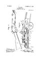
- Figure 1 is a side elevation of a repeating rifle embodying my improvements.
- Fig. 2 is a vertical longitudinal sectional view through the breech or gun lock and adjacent parts, showing the elements constituting my improvements in elevation.
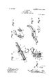
- Fig. 3 is a perspective view of the breech-bolt detached.
- Fig. 4 is a cross-sectional view of the breech-bolt, taken on the line 4 4 of Fig. 3.
- Fig. 5 is likewise a crosssection taken on the line 5 5 of Fig. 3.
- Fig. 6 is a perspective view of the carrier.
- Fig. 7 is a transverse vertical section through the gun, taken on the line 7 7 of Fig. 2.
- Fig. 8 is a separate view of one of the frictionsprings for the sides of the carrier.
- 1 designates the barrel
- the magazine 3 the butt-stock; 4, the magazine-cut-oif spring 5, the breech-bolt; 6, the locking-bolt; 7, the carrier and lift-up 8, the trigger; 9, the hammer, and 10 the firing-pin, mostly concealed in the breech-bolt.
- the lift-up or carrier has its rear portion made in substantial crescent shape in side elevation, and it is pivoted at about the middle of the crescent-shaped part on the pin 11 to the body of the frame.
- a spring 12 on each side of the carrier 7 is held in place by said pin and operates frictionally against the 4 interior of the gun to steady the motion of the carrier,.and the lower end of the lockingbolt 6, which projects through the breechbolt, operates on the upper face of the carrier to impart to it its movements, as will presently appear.
- the part of the lockingbolt projecting above the breech-bolt is pro-' vided with a knob 13 to facilitate the operation of the parts, particularly the breechbolt 5.
- the latter device is for the .most part substantially round and carries the firing-pin 10 and extractor 14. It is flattened at 15 on the underneath side from where the locking bolt passes through it to within three-eighths of the end. The flattening is only slight and is so made as to give room for the operation of the rear end of the carrier. It also has a slight tongue 16 on its lower side, made by cutting away a part of the surface at its sides. The tongue works in a slot 17, made in the carrier for that purpose. This tongue protrudes beyond the end of the bolt and is turned at an angle with the latter. This protrusion operates to push the cartridge out of the carrier into the barrel on closing the bolt.
- the locking-bolt as herein shown is about three inches long and is turned. at nearly a right angle at a point just above the breechbolt, through which it passes, the lower end extending below the breech-bolt, as stated, so that its lower end may operate on the carrler.
- the front end of the carrier 7 in normal or balanced position extends nearly parallel with the barrel, and there is a rounded trough 18 made in the upper side of said end for the reception of the cartridge.
- the lower end of the locking-bolt operating on the upper face of the forward part of the cam or crescent-shaped portion of the carrier depresses the said forward end, so as to cause it to encounter the cut-ofi spring 4 of the magazine and permit a cartridge to escape from the magazine into the trough 18 of the carrier.
- the gun is cocked by pulling the breech-bolt back over the hammer, and by this action the empty shell in the barrel will be extracted by means of a hook 19, that catches over the rim of the cartridge and pulls it out.
- a carrier or lifter for a repeating rifle having substantially one half of its efficient upper surface of crescent shape and the other half of said face substantially straight in combination with the lower end of the locking-bolt, which engages said efficient upper crescent shaped surface of the carrier or lifter and rocks the same.
- a carrier or lifter for a repeating rifle having the upper half of its eflicient surface cam-shaped, and the other half or part provided with a trough to receive a cartridge in combination with the lower end of the locking-bolt which engages said eflicient camshaped surface and operates the said lifter or carrier.
- a pivoted carrier or lifter in combination with a breech-bolt, provided with a locking-pin having its lower end adapted to engage and rock said carrier to causeit to receive a cartridge and carry it into position to be loaded into the barrel of the gun.
- a pivoted carrier or lifter in combination with a breech-bolt, provided with a locking-pin having its lower end adapted to engage and rock said carrier to cause it to receive a cartridge and carry it into position to be loaded. into the barrel of the gun and a breech-bolt arranged to be moved to load the cartridge into the barrel.
Landscapes
- Engineering & Computer Science (AREA)
- General Engineering & Computer Science (AREA)
- Portable Nailing Machines And Staplers (AREA)
Description
PATENTED JAN. 2, 1906.
W. E. CLAY. MAGAZINE RIFLE.
APPLICATION FILED JULY 1, 1905.
2 SHEETS-SHEET 1.
WWW
PATENTED JAN. 2, 1906. W. E. CLAY.
, MAGAZINE RIFLE.
APPLICATION rum) JULY 1, 1905.
2 SHEETS-SHEET 2.
UNITED {STATES PATENT- @FFICE. WILLIAM E. CLAY, OF WILLIAMSTOWN, KENTUCKY.
MAGAZINE-RIFLE.
Specification of Letters Patent.
Patented Jan. 2, 1906.
To all whom it may concern.-
Be it known that I, WILLIAM E. CLAY, a citizen of the United States, residing at Williamstown, in the county of Grant and State of Kentucky, have invented new and useful Improvements in Magazine-Rifles, of which the following is a specification.
This invention has relation to repeating or magazine rifles; and it has for its object the simplification, strengthening, and cheapening the cost of manufacture, besides rendering its operation more certain than heretofore, and otherwise bettering it.
The nature of the invention resides for the most part in improvements in means consisting of a lifter or carrier for receiving the cartridge from the magazine and in the mode of operating the same to lift or carry up the said cartridge into position to be loaded into the barrel of the gun by the breech-bolt and also in the improved means for locking the breech-bolt, all as will appear from a careful inspection of the drawings hereto annexed, in connection with the description hereinafter given of the construction and mode of operation of the arm.
Of the said drawings, Figure 1 is a side elevation of a repeating rifle embodying my improvements. Fig. 2 is a vertical longitudinal sectional view through the breech or gun lock and adjacent parts, showing the elements constituting my improvements in elevation. Fig. 3 is a perspective view of the breech-bolt detached. Fig. 4 is a cross-sectional view of the breech-bolt, taken on the line 4 4 of Fig. 3. Fig. 5 is likewise a crosssection taken on the line 5 5 of Fig. 3. Fig. 6 is a perspective view of the carrier. Fig. 7 is a transverse vertical section through the gun, taken on the line 7 7 of Fig. 2. Fig. 8 is a separate view of one of the frictionsprings for the sides of the carrier.
Similar figures of reference indicate similar parts or features, as the case may be, wherever they occur.
The description hereinafter given will be closely confined to an explanation of the parts and features constituting my improvements. Parts that are old are commonly well understood, so that they need no detailed description.
In the drawings, 1 designates the barrel;
2, the magazine 3, the butt-stock; 4, the magazine-cut-oif spring 5, the breech-bolt; 6, the locking-bolt; 7, the carrier and lift-up 8, the trigger; 9, the hammer, and 10 the firing-pin, mostly concealed in the breech-bolt.
The lift-up or carrier has its rear portion made in substantial crescent shape in side elevation, and it is pivoted at about the middle of the crescent-shaped part on the pin 11 to the body of the frame. A spring 12 on each side of the carrier 7 is held in place by said pin and operates frictionally against the 4 interior of the gun to steady the motion of the carrier,.and the lower end of the lockingbolt 6, which projects through the breechbolt, operates on the upper face of the carrier to impart to it its movements, as will presently appear. The part of the lockingbolt projecting above the breech-bolt is pro-' vided with a knob 13 to facilitate the operation of the parts, particularly the breechbolt 5. The latter device is for the .most part substantially round and carries the firing-pin 10 and extractor 14. It is flattened at 15 on the underneath side from where the locking bolt passes through it to within three-eighths of the end. The flattening is only slight and is so made as to give room for the operation of the rear end of the carrier. It also has a slight tongue 16 on its lower side, made by cutting away a part of the surface at its sides. The tongue works in a slot 17, made in the carrier for that purpose. This tongue protrudes beyond the end of the bolt and is turned at an angle with the latter. This protrusion operates to push the cartridge out of the carrier into the barrel on closing the bolt.
The locking-bolt as herein shown is about three inches long and is turned. at nearly a right angle at a point just above the breechbolt, through which it passes, the lower end extending below the breech-bolt, as stated, so that its lower end may operate on the carrler.
The front end of the carrier 7 in normal or balanced position extends nearly parallel with the barrel, and there is a rounded trough 18 made in the upper side of said end for the reception of the cartridge.
When the breech-bolt is moved forward,
the lower end of the locking-bolt operating on the upper face of the forward part of the cam or crescent-shaped portion of the carrier depresses the said forward end, so as to cause it to encounter the cut-ofi spring 4 of the magazine and permit a cartridge to escape from the magazine into the trough 18 of the carrier. The gun is cocked by pulling the breech-bolt back over the hammer, and by this action the empty shell in the barrel will be extracted by means of a hook 19, that catches over the rim of the cartridge and pulls it out.
When the front end of the carrier contain ing a cartridge received from the magazine is in elevated position, by shoving the breechbolt forward it will engage the rear end of the cartridge and push it into the barrel. It-
is to be noticed that the bottom side of the bolt does not come into contact with the lifter or carrier until the cartridge is almost entirely Within the barrel. Then by turning the knob of the locking-bolt to the right the gun will be locked on both sideson the right side by the upper part of the locking-bolt engaging the notch 20, formed in the side of the slot in which the said upper part moves, and on the left side by the lower end of the locking-bolt beingturned into a notch 21 on the interior of the frame-thus forming a double look, as stated. When the gun is closed and locked, the front end of the lifter or carrier is lowered, which pushes down the magazine cut-off 4 and receives the next cartridge in the trough 18, as before indicated.
The durability, simplicity of construction, and little liability of the arm to get out of order are secured mainly through its simplicity of construction and positive action of substantially all of the parts used.
It is obvious that mechanical change may be made in the form and arrangement of parts comprising the improvements Without departing from the nature or spirit of the invention.
I claim 1. A carrier or lifter for a repeating rifle having substantially one half of its efficient upper surface of crescent shape and the other half of said face substantially straight in combination with the lower end of the locking-bolt, which engages said efficient upper crescent shaped surface of the carrier or lifter and rocks the same.
2. A carrier or lifter for a repeating rifle having the upper half of its eflicient surface cam-shaped, and the other half or part provided with a trough to receive a cartridge in combination with the lower end of the locking-bolt which engages said eflicient camshaped surface and operates the said lifter or carrier.
3. In a repeating rifle of the character described, a pivoted carrier or lifter, in combination with a breech-bolt, provided with a locking-pin having its lower end adapted to engage and rock said carrier to causeit to receive a cartridge and carry it into position to be loaded into the barrel of the gun.
4. In a repeating rifle of the character described, a pivoted carrier or lifter, in combination with a breech-bolt, provided with a locking-pin having its lower end adapted to engage and rock said carrier to cause it to receive a cartridge and carry it into position to be loaded. into the barrel of the gun and a breech-bolt arranged to be moved to load the cartridge into the barrel.
In testimony whereof I aflix my signature in presence of two subscribing Witnesses.
WILLIAM E. CLAY.
Witnesses TIM NEEDHAM, G. W. HILL.
Priority Applications (1)
| Application Number | Priority Date | Filing Date | Title |
|---|---|---|---|
| US26794105A US809094A (en) | 1905-07-01 | 1905-07-01 | Magazine-rifle. |
Applications Claiming Priority (1)
| Application Number | Priority Date | Filing Date | Title |
|---|---|---|---|
| US26794105A US809094A (en) | 1905-07-01 | 1905-07-01 | Magazine-rifle. |
Publications (1)
| Publication Number | Publication Date |
|---|---|
| US809094A true US809094A (en) | 1906-01-02 |
Family
ID=2877575
Family Applications (1)
| Application Number | Title | Priority Date | Filing Date |
|---|---|---|---|
| US26794105A Expired - Lifetime US809094A (en) | 1905-07-01 | 1905-07-01 | Magazine-rifle. |
Country Status (1)
| Country | Link |
|---|---|
| US (1) | US809094A (en) |
-
1905
- 1905-07-01 US US26794105A patent/US809094A/en not_active Expired - Lifetime
Similar Documents
| Publication | Publication Date | Title |
|---|---|---|
| US809094A (en) | Magazine-rifle. | |
| US1331154A (en) | Bolt-action gun | |
| US782716A (en) | Bolt-gun. | |
| US207689A (en) | Improvement in breech-loading fire-arms | |
| US187462A (en) | Improvement in breech-loading fire-arms | |
| US940191A (en) | Magazine-firearm. | |
| US959942A (en) | Firearm. | |
| US210091A (en) | Improvement in magazine fire-arms | |
| US710094A (en) | Magazine-gun. | |
| US1077228A (en) | Repeating firearm. | |
| US574409A (en) | Breakdown firearm | |
| US233901A (en) | Breech-loading fire-arm | |
| US288618A (en) | Breech-loading gun | |
| US549722A (en) | Lewis l | |
| US549345A (en) | Box-magazine firearm | |
| US232919A (en) | Theodore d | |
| US147457A (en) | Improvement in breech-loading fire-arms | |
| US338188A (en) | Fire-arm | |
| US269660A (en) | Magazine-gun | |
| US327860A (en) | Breech-loading fire-arm | |
| US743002A (en) | Rapid-fire pistol. | |
| US357460A (en) | Peters | |
| US495298A (en) | Ward george parry | |
| US478221A (en) | burgess | |
| US177905A (en) | Improvement in breech-loading fire-arms |