US809082A - Internal-combustion engine. - Google Patents
Internal-combustion engine. Download PDFInfo
- Publication number
- US809082A US809082A US19396104A US1904193961A US809082A US 809082 A US809082 A US 809082A US 19396104 A US19396104 A US 19396104A US 1904193961 A US1904193961 A US 1904193961A US 809082 A US809082 A US 809082A
- Authority
- US
- United States
- Prior art keywords
- cylinders
- pump
- cylinder
- crank
- power
- Prior art date
- Legal status (The legal status is an assumption and is not a legal conclusion. Google has not performed a legal analysis and makes no representation as to the accuracy of the status listed.)
- Expired - Lifetime
Links
- 238000002485 combustion reaction Methods 0.000 title description 10
- 238000004891 communication Methods 0.000 description 5
- 230000006854 communication Effects 0.000 description 5
- 239000012530 fluid Substances 0.000 description 4
- 230000006835 compression Effects 0.000 description 3
- 238000007906 compression Methods 0.000 description 3
- 238000004880 explosion Methods 0.000 description 3
- 238000001816 cooling Methods 0.000 description 2
- 239000000446 fuel Substances 0.000 description 2
- 241000239290 Araneae Species 0.000 description 1
- 238000007664 blowing Methods 0.000 description 1
- 230000008602 contraction Effects 0.000 description 1
- 238000010168 coupling process Methods 0.000 description 1
- 238000005859 coupling reaction Methods 0.000 description 1
- 238000007599 discharging Methods 0.000 description 1
- 239000002360 explosive Substances 0.000 description 1
- 239000000463 material Substances 0.000 description 1
- 239000000203 mixture Substances 0.000 description 1
- 230000008520 organization Effects 0.000 description 1
- 230000000979 retarding effect Effects 0.000 description 1
- 230000002000 scavenging effect Effects 0.000 description 1
Images

Classifications
-
- F—MECHANICAL ENGINEERING; LIGHTING; HEATING; WEAPONS; BLASTING
- F02—COMBUSTION ENGINES; HOT-GAS OR COMBUSTION-PRODUCT ENGINE PLANTS
- F02B—INTERNAL-COMBUSTION PISTON ENGINES; COMBUSTION ENGINES IN GENERAL
- F02B57/00—Internal-combustion aspects of rotary engines in which the combusted gases displace one or more reciprocating pistons
- F02B57/08—Engines with star-shaped cylinder arrangements
Landscapes
- Engineering & Computer Science (AREA)
- Chemical & Material Sciences (AREA)
- Combustion & Propulsion (AREA)
- Mechanical Engineering (AREA)
- General Engineering & Computer Science (AREA)
- Cylinder Crankcases Of Internal Combustion Engines (AREA)
Description
PATENTED JAN. 2, 1906.
I. WEIGHT. INTERNAL GOMEUSIION ENGINE.
AVPPLIUATION FILED FEB.17. 1904.
2 SHEETS-SHEET l.
5.. 5 V/nllllilInrllllllllllln W/TNESSES:
PATENTED JAN. 2, 1906.
z SHEETS-SHEET 2.
`T. WRIGHT. INTERNAL COMBUSTION ENGINE. APPLICATION FILED PEB. 17. 1904.
UNITED STATES PATENT OFFICE.
THOMAS WRIGHT, `OF JERSEY CITY, NEW JERSEY.
specification of Letters Patent.
Patented J an. 2, 1906.
Application led February 17, 1904. Serial No. 193,961.
To LZZ whom, it may concern:
Be it known that I, THOMAS WRIGHT, a citi- Zen of the United States, and a resident of Jersey City, in the county of Hudson and State of New Jersey, have invented a new and Improved Internal-Combustion Engine, of which the following is afull, clear, and exact description. i
This invention relates to an internal-combustion engine of the type in which a plurality of cylinders are arranged to swing around a stationary cranked shaft, the movement of the engine being taken from a part connected to move with the cylinders.
The leading feature of my present invention resides in the arrangement of a number of pump-cylinders alternately with the powercylinders and in providing valve-controlled communications between each pump-cylinder and the two adjacent power-cylinders. By this organization of the elements of the engine the direction of rotation may be reversed at will, the pumps acting to supply either the power-cylinders to their right or to their left, according to the direction of movement. Spring-seated valves may be employed, dispensing entirely With mechanical valve-driving gear, and by the provision of exhaustports at the end of the stroke in the powercylinders and the arrangement of the pump communica tions at the outer ends of the powercylinders the engine may be given a two-cycle action, with a thorough scavenging and cooling of the cylinders at the end of each stroke.
The invention involves various other features of major or minor importance, and all will be fully set forth hereinafter..
This Specification is an exact description of one example of my invention, while the claims dene the actual scope thereof.
Reference is to be had to the accompanying drawings, forming a part of this specication, in which similar characters of reference indicate corresponding parts in all the views.
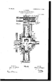
Figure 1 is a vertical cross-section of the engine. Fig. 2 is a vertical longitudinal section of the same, and Fig. 3 is an enlarged detail view of one of the cylinder inlet-valves.
' 10 indicates a suitably-sustained stationary shaft having thereon a crank 11. Mounted suitably on the shaft 10 or on any other desired support are the webs 12 and 14 of the pump-cylinders 15 and power-cylinders 16. These cylinders are arranged alternately around the center of the shaft 10, and, as here shown, there are three pump-cylinders and three power-cylinders. The pump-pistons 17 and power-pistons 18 have rods 19 and 2O connected withY the crank 11, so that the cylinders may turn around the center of the shaft 10, and the power-pistons 18, acting through the rods 2O on the crank 11, will cause the continued movement of the engine. The motive power is taken from the cylinders, for example, through the medium of a hub-like projection 14 on the web 14, to which a gear 21 is attached. Preferably the rods 19 and 2O are formed with enlargements 45, which are fitted snugly to the wrist-pin of the crank 11 and held thereon by means of suitably-formed rings 46, (see Fig. 2,) the arrangement being such as will permit the necessary independent movement of the enlargements of the rods with respect to the crank a-nd rings.
22 (see Fig. 2) indicates the source of the Vmixture of air and fuel constituting the combustible charge. This is illustrated as in the form of a pipe or duct leading to a stationary annular chamber 23, which is adapted to be suitably supported independently of the moving parts of the engine. The web 12 has passages 12 therein, the receiving ends of which are inclosed by the annular chamber 23, and in this manner the passages 12 are continually in communication with the source of fuel. Any suitable Huid-tight connection may be effected between the parts 12 and 23 which will allow the free rotation of the part 12 with respect to the chamber 23. In the drawings I have shown V-shaped ribs 12 formed on thev web 12 and engaging in annular grooves in the walls of the chamber 23. From the passages 12 pipes 24 pass, respectively, out- `These pipes are provided with any desired form of check-valves 26, said valves opening into the pump-cylinders, as indicated in Fig. 2. In this manner the explosive or combustible mixture is continually supplied to the outer ends of the pump-cylinders.
As shown best in Fig. 1, each pump-cylinder has free communication with two pipes 27. These pipes pass from opposite sides of the respective cylinders to the heads 28 of the power-cylinders. Puppet or other valves 29 command the pipes 27, said valves being located at the heads 28 and opening thereinto, as shown. The valves 29 are yieldingly seated by springs 30 engaging with their stems, preferably in a manner hereinafter fully set forth. At their inner portions the cylinders 16 are provided with exhaust-ports 30, which TOO TIO
communicate with ducts 31, formed on the outer walls of the cylinders, and said ducts in turn communicate with pipes 32, (see Fig. 2,) which lead to lpassages 14h in 'the web 14. Said passages 14" are similar to the passages 12 and communicate with a stationary annular chamber 33, supported in any desired manner and similar to the chamber 23. 34 indicates an exhaust-pipe passing from the chamber 33. Said chamber may have any desired air-tight connection with the web 14 allowing a free rotation of the web. In the drawings I have shown ribs 14C engaging in corresponding grooves in the walls of the chamber 33.
In the operation of the engine, assuming that the cylinders are moving in the direction of the arrow a in Fig. 1 and that the pistons are moving in the cylinders in the direction of the arrows respectively applied thereto, it will be seen that the upper righthand power-piston is moving under the force of an explosion within its cylinder, imparting to the engine an impulse in the direction of the arrow a. Simultaneously the lower righthand pump-piston is moving inward to draw into its cylinder a charge of the combustible material. The lowermost power-cylinder has its exhaust-ports uncovered, and the lower left-hand pump is forcing a fresh charge through the connecting-pipe 27 into the said lowermost power-cylinder, causing the products of previous combustion therein to be forced out through the exhaust-ports and cooling the cylinder-walls. The left-hand powerpiston is moving outward to compress the charge therein, and the uppermost pump is at the end of its stroke, having previously forced into the left-hand power-cylinder the charge being compressed therein. It will be observed, therefore, that throughout the operation of the engine one of the three powercylinders is having a charge compressed therein, the second is exhausted, and the third is compressing the charge. The power-cylinders are supplied with the charge respectively by the pumps immediately pressing' them in the direction of revolution. All the charge is drawn through the pipe 24 and past the valve 26 into one of the pumps upon the return movement of the piston, the valve 26 closes, and the charge is forced out through the pipe 27, leading to the power-cylinder with which the pumpis associated. The charge cannot pass to the other adjacent power-cylinder, since compression is already going on therein and the compression is higherthan in the Erst-named power-cylinder. The said pump reaches the end of its discharging movement and begins to return before the powerpiston to which the pump is related has finished the compression-stroke, and consequently the valve 29, controlling the communication between the pump and power cylinder, closes both under the iniiuence of the suction-stroke of the pump and the continued compressionstroke of the power-piston. After the final compression of the charge it is ignited, the power-piston moves outward under the impulse of the explosion, and the above operation is repeated in the power-cylinder by the blowing thereinto of the fresh charges, which scavenges and cools the cylinder as explained.
It will be observed that owing to the connections between the pump and power cylinders as set forth heretofore and to the arrangement of the cylinders with respect to the crank 1,1 the engine may be reversed at will by advancing or retarding the sparking or other igniting means, so that the explosion will occur at one side or the other of the vertical center of the crank 11.
35 indicates (see Fig. 2) the sparking plugs which preferably I employ for the purposes of ignition. Any suitable mechanism may be used in connection with these plugs for controlling the sparkin the manner essential to the various operations of the engine, or, if desired, any other form of igniting means may be employed.
As shown best in Fig. 3, the power-cylinder heads 28 have tubular extensions 36 formed thereon, and in said extensions are fitted the sleeves37,carryingthevalves29. Saidsleeves are formed with spiders 38, constituting the guides of the valve-stems 39, and to said stems the before-referred-to springs 30 are applied, which serve yieldingly to seat the valves. The valves are seated on the inner ends of the tubular seats or sleeves 37, and the pipes 27 are joined to the tubular extensions 36 by means of screw-couplings 40, as shown. At the ends of the pipes 27 adjacent to the pumpcylinder heads 25 connection is eifected through the medium of stuffing-boxes 41 and tubular extensions 42, which allow longitudinal movement of the pipes not only to provide for expansion and contraction of the pipes, but also to enable the pipes to be placed in and removed from their proper position in the machine.
Various changes in the form, proportions, and minor details of my invention may be resorted to at will without departing from the spirit and scope thereof. Hence I consider myself entitled to all such variations as may lie within the intent of my claims.
Having thus described my invention, I claim as new and desire to secure by Letters Patent- 1. In an internal-combustion engine, the combination of a plurality of working cylinders, a plurality of pump-cylinders arranged alternately with respect to the working cylinders, a crank-shaft common to all of the cylinders, means for supporting all of the cylinders to turn around the center of said shaft, pistons operating in the cylinders', connections between the pistons and the crank, means controlling fluid movement between the various cylinders, said means comprising connections IOO IIO
between the pump-cylinders and the two working cylinders adjacent thereto, and valves controlling said connections and seating against pressure in the working cylinders.
2. In an internal-combustion engine, the combination of a plurality7 of working cylinders, a plurality of pump-cylinders arranged alternately with respect-to the working cylinders, a crank-shaft common to all of the cylinders, means for supporting the cylinders to turn around the center of the shaft, pistons operating in the cylinders, connections between the pistons and the crank, means for controlling fluid movement to and from the cylinders, said means including exhaust-ports in the working cylinders at the limit of the working stroke of their pistons, connections extending from the heads of the pump-cylinders to the heads of the working cylinders at each side of the pump-cylinders, and valves controlling said connections and seating against pressure Within the working cylinders.
3. In an internal-combustion engine, the combination of a working cylinder, a pumpcylinder arranged at each side thereof, a crankshaft common to the cylinders, means for supporting the cylinders to turn around the center of the crank-shaft, pistons operating in the cylinders, connections between the pistons and crank-shaft, means controlling fluid movement in the cylinders, said means including connections between the outer ends of the pump-cylinders and the outer end of the working cylinder, valves in said connections seating against pressure in the working cylinders, and an exhaust-port in the working cylinder at the end of the expansion-stroke of the piston.
4. In an internal-combustion engine, the combination of a plurality of working cylinders and an equal number of pump-cylinders respectively arranged between the working cylinders, a crank-shaft central to all of the cylinders, means for supporting the cylinders to turn around the center of the crank-shaft, pistons operating in the cylinders, connections between the pistons and crank-shaft, means for controlling iuid movement to and from the cylinders, said means including exhaust-v ports in the working cylinders at the limit of the expansion-strokes of the pistons thereof, connections between each pump-cylinder and the two working cylinders adjacent thereto, and valves controlling said connections.
5. In an internal-combustion engine, the combination of a plurality of working cylinders and an equal number of pump-cylinders respectively arranged between the working cylinders, a crank-shaft central to all of the cylinders, means for supporting the cylinders to turn around the center of the crank-shaft, pistons operating in the cylinders, connections between the pistons and crank-shaft, means for controlling fluid movement to and from the cylinders, said means including exhaustports in the working cylinders at the limit of the expansion-strokes of the pistons thereof, connections between each pump-cylinder and the two working cylinders adjacent thereto, and valves controlling said connections, said valves being located respectively adjacent to the working cylinders and seating against the pressure therein.
In testimony whereof I have signed my name to this specification in the presence of two subscribing witnesses.
THOMAS WRIGHT.
Witnesses:
JOHN F. WRIGHT, EUGENE T. WRIGHT.
Priority Applications (1)
| Application Number | Priority Date | Filing Date | Title |
|---|---|---|---|
| US19396104A US809082A (en) | 1904-02-17 | 1904-02-17 | Internal-combustion engine. |
Applications Claiming Priority (1)
| Application Number | Priority Date | Filing Date | Title |
|---|---|---|---|
| US19396104A US809082A (en) | 1904-02-17 | 1904-02-17 | Internal-combustion engine. |
Publications (1)
| Publication Number | Publication Date |
|---|---|
| US809082A true US809082A (en) | 1906-01-02 |
Family
ID=2877563
Family Applications (1)
| Application Number | Title | Priority Date | Filing Date |
|---|---|---|---|
| US19396104A Expired - Lifetime US809082A (en) | 1904-02-17 | 1904-02-17 | Internal-combustion engine. |
Country Status (1)
| Country | Link |
|---|---|
| US (1) | US809082A (en) |
Cited By (1)
| Publication number | Priority date | Publication date | Assignee | Title |
|---|---|---|---|---|
| US2774341A (en) * | 1954-11-22 | 1956-12-18 | Paul M Morse | Rotary internal combustion engine |
-
1904
- 1904-02-17 US US19396104A patent/US809082A/en not_active Expired - Lifetime
Cited By (1)
| Publication number | Priority date | Publication date | Assignee | Title |
|---|---|---|---|---|
| US2774341A (en) * | 1954-11-22 | 1956-12-18 | Paul M Morse | Rotary internal combustion engine |
Similar Documents
| Publication | Publication Date | Title |
|---|---|---|
| US1040472A (en) | Gas-engine. | |
| US809082A (en) | Internal-combustion engine. | |
| US1042505A (en) | Internal-combustion engine. | |
| US1154366A (en) | Internal-combustion engine. | |
| US719547A (en) | Explosive-engine. | |
| US806195A (en) | Motor and engine. | |
| US1018093A (en) | Internal-combustion engine. | |
| US931531A (en) | Gas-engine. | |
| US1272305A (en) | Internal-combustion engine. | |
| US273269A (en) | Gas-engine | |
| US730345A (en) | Two-cycle gas-engine. | |
| US739405A (en) | Fluid-motor. | |
| US355101A (en) | Gas-engine | |
| US809451A (en) | Double-acting explosive-engine. | |
| US729194A (en) | Gas-engine. | |
| US1111074A (en) | Internal-combustion engine. | |
| US680907A (en) | Multiple-cylinder explosive-engine. | |
| US568814A (en) | Gas-engine | |
| US1172124A (en) | Internal-combustion engine. | |
| US419806A (en) | Carl w | |
| US979971A (en) | Two-cycle internal-combustion motor. | |
| US998570A (en) | Internal-combustion engine. | |
| US1344641A (en) | Internal-combustion engine | |
| US1317939A (en) | Combustion-engine. | |
| US889887A (en) | Gas-engine. |