US809079A - Thill-coupling. - Google Patents
Thill-coupling. Download PDFInfo
- Publication number
- US809079A US809079A US24177105A US1905241771A US809079A US 809079 A US809079 A US 809079A US 24177105 A US24177105 A US 24177105A US 1905241771 A US1905241771 A US 1905241771A US 809079 A US809079 A US 809079A
- Authority
- US
- United States
- Prior art keywords
- frame
- rods
- disk
- yoke
- thill
- Prior art date
- Legal status (The legal status is an assumption and is not a legal conclusion. Google has not performed a legal analysis and makes no representation as to the accuracy of the status listed.)
- Expired - Lifetime
Links
- 238000010168 coupling process Methods 0.000 title description 7
- 238000005859 coupling reaction Methods 0.000 title description 7
- 230000033001 locomotion Effects 0.000 description 15
- 241001465754 Metazoa Species 0.000 description 3
- 238000010276 construction Methods 0.000 description 1
- 230000036461 convulsion Effects 0.000 description 1
- 230000008878 coupling Effects 0.000 description 1
- 238000012216 screening Methods 0.000 description 1
Images
Classifications
-
- B—PERFORMING OPERATIONS; TRANSPORTING
- B62—LAND VEHICLES FOR TRAVELLING OTHERWISE THAN ON RAILS
- B62C—VEHICLES DRAWN BY ANIMALS
- B62C5/00—Draught assemblies
Definitions
- My invention relates to a coupling for connecting the thills or tongue of a vehicle with the axle or any part of the frame thereof.
- the principal objects of the invention are to provide means whereby the exertion of the pull upon the thills or tongue will be yieldingly resisted, so that the sudden starting up of the draft-animal will not cause a sudden jolt of the vehicle and so as to relieve the animal and vehicle from sudden strains of all kinds, also to provide similar means for causing the same kind of a resistance when the animal backs or the vehicle is pushed toward it.
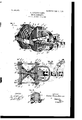
- Figure 1 is a perspective view of one embodiment of my invention.
- Fig. 2 is a vertical longitudinal sectional view thereof through the center, and
- Fig. 3 is a fragmentary sectional view of certain details.
- the axle of the vehicle is represented by the letter a; but it will be understood that any other portion of the frame may take the place of the axle for the puroose ofV attaching the device to the vehicle.
- a frame Z Upon this part of the frame or axle is applied a frame Z.
- This frame is provided with a pair of forwardlyprojecting brackets c. Each of these brackets is provided with a longitudinal slot c and with a guide c2. Through the slots passes a pin ZZ, by means of which the thills e or the tongue of the vehicle may be pivotally attached.
- the pin is provided with a square nut Z or other convenient device upon each end, these nuts being adapted to move in the guidesZ and to be accurately guided thereby, so that the pin will move forward and backward in a straight line only.
- a yoke f Connected with the pin is a yoke f, this yoke being provided with a pair of projections f', through which the pin passes and by which the yoke is connected with the pin.
- the yoke preferably projects both upwardly and downwardly from the first-mentioned projections and terminates in a pair of feet f2, one above and one below the frame Z. These feet are preferably mounted at the ends of a pair of projections Z upon the frame Z, which, as shown, consists of two parts.
- a disk g whic is free to move with respect to the frame Z.
- This disk is provided with perforations g', through which pass rods Zt and ZZ, the rodsv Zt being provided with nuts Zt', which are secured to the front side of the feet f 2, through which these rods pass.
- the rod 7c is secured in the frame Z in any desired manner.
- This disk is also provided with a notch g2 on each side, fitting a plate Z2, which is mounted on each side of the frame Z, the two plates Z2 constituting guides for the disk g in an obvious manner and constraining the disk to move longitudinally in a direction parallel to the movement of the pin CZ.
- Asecond disk Z is mounted at the opposite end of the rod lc.
- This disk is preferably formed in a similar shape to the disk g and has perforations Z' and notches Z2 similar to the perforations g and notches g2 and operating in a similar manner.
- This disk is also free to slide upon the rods It and 7c and the guide-plates Z2.
- a plate m At the rear of the disk Z is a plate m, which is provided with perforations m' for the reception of the rods Zt and 7c.
- the rods Zt are free to slide through their respective perforations; but the rod Ze is secured to the plate m by the use of a nut Ze' or in any other desired manner.
- the plate m is substantially fixed in a stationary position with respect to the frame Z, for it is prevented from moving backwardly therefrom by the nut In', while it is normally prevented from moving toward the frame Z by means to be described, although it is not essential that it should be rigidly fixed, and if it moves toward the frame Z no harm will be done.
- This plate can conveniently be absolutely fixed upon the guideplates Z2,if desired, and this construction comes within the scope of my invention.
- the frame Z has screw-threaded projectionsZa, by means of which plates Z4 are secured to it for holding the yoke or axle a.
- the plate g is preferably cut at g3 to accommodate the plates Z4.
- the plate m is provided with notches m2, which receive nuts 71,2, fixedly mounted upon the rods t. rlhese nuts, it will be observed, prevent the movement of the rods /L rearwardly from the position shown in Fig. 2,
- a thill-coupling comprising means for receiving a thill or the like, means 'for guiding the thill to move rectilinearly, and yielding means for resisting ⁇ motion of the thill in both directions.
- a thill-coupling comprising a guide, a yoke adapted to be guided thereby and to receive a thill or the like, yielding means for resisting' a forward pull on' the thill, and yielding means for resisting a backward thrust on the thill.
- a 'thill-coupling comprising a frame means by which its motion is controlled by said guides, and means for resisting motion of the yoke in both directions.
- a movable yoke having feet provided with perforations, a plurality of rods one mounted to move in each oi' said perforations, a nut upon each of said rods adapted to engage said feet, a disk provided with perforations for receiving said rods and mounted adjacent to said feet, a second disk similarly formed and spaced from the ⁇ i1-st disk, a spring located between said disks, a stationary frame on the outside of one ot' said disks, a plate on the outside of the other disk and connected with said frame, and means for preventing the rods from moving beyond said plate in one direction.
- a movable yoke having feet provided with perforations, a plurality of rods one mounted to move in each of said perforations, a nut upon each of said rods adapted to engage said feet, a disk provided with peiforations for receiving said rods and mounted adjacent to said feet, a second disk similarly formed and spaced from the first disk, a spring located between said disks, a stationary frame on the outside of one ot' said disks, a plate on the outside of the other disk and connected with said frame, means for preventing the rods from moving beyond said plate in one direction, means on the frame for guiding said disks in a straight line, and a projection on the frame for guiding the yoke in a line parallel vto that in which the disks are guided.
Landscapes
- Engineering & Computer Science (AREA)
- Transportation (AREA)
- Mechanical Engineering (AREA)
- Vehicle Cleaning, Maintenance, Repair, Refitting, And Outriggers (AREA)
Description
A N0.'809,o79. f v PATENTBD JAN. 2, 190e. C. VIVES-NAVARRO. THILL GOUPLING.
APPLICATION FILED JAN. I9, 1905.
-llummml WITNESSES.'
TTOHNEYS CARLOS vivas-NAVARRO. or PONCE, PORTO Rico.
THILL-COUPLING.
Specification of Letters 1l:"atent.
Patented Jan. 2, 1906.
Application fled January 19, 1905. Serial No. 241,771.
To aZZ whom, it may concern:
Be it known th at I, CARLOS VIVES-NAVARRO, a citizen of Porto Rico, and a resident of Ponce, Porto Rico, have invented a new and Improved Thill-Coupling, of which the following is a full, clear, and exact description.
My invention relates to a coupling for connecting the thills or tongue of a vehicle with the axle or any part of the frame thereof.
The principal objects of the invention are to provide means whereby the exertion of the pull upon the thills or tongue will be yieldingly resisted, so that the sudden starting up of the draft-animal will not cause a sudden jolt of the vehicle and so as to relieve the animal and vehicle from sudden strains of all kinds, also to provide similar means for causing the same kind of a resistance when the animal backs or the vehicle is pushed toward it.
Further objects of the invention will appear in the course of the subjoined description.
Reference isto be had to the accompanying' drawings, forming a part of this specification, in which similar characters of reference indicate corresponding parts in all the figures.
Figure 1 is a perspective view of one embodiment of my invention. Fig. 2 is a vertical longitudinal sectional view thereof through the center, and Fig. 3 is a fragmentary sectional view of certain details.
The axle of the vehicle is represented by the letter a; but it will be understood that any other portion of the frame may take the place of the axle for the puroose ofV attaching the device to the vehicle. Upon this part of the frame or axle is applied a frame Z. This frame is provided with a pair of forwardlyprojecting brackets c. Each of these brackets is provided with a longitudinal slot c and with a guide c2. Through the slots passes a pin ZZ, by means of which the thills e or the tongue of the vehicle may be pivotally attached. The pin is provided with a square nut Z or other convenient device upon each end, these nuts being adapted to move in the guidesZ and to be accurately guided thereby, so that the pin will move forward and backward in a straight line only. Connected with the pin is a yoke f, this yoke being provided with a pair of projections f', through which the pin passes and by which the yoke is connected with the pin. The yoke preferably projects both upwardly and downwardly from the first-mentioned projections and terminates in a pair of feet f2, one above and one below the frame Z. These feet are preferably mounted at the ends of a pair of projections Z upon the frame Z, which, as shown, consists of two parts. l v Back of the projections Z/ is a disk g, whic is free to move with respect to the frame Z. This disk is provided with perforations g', through which pass rods Zt and ZZ, the rodsv Zt being provided with nuts Zt', which are secured to the front side of the feet f 2, through which these rods pass. The rod 7c is secured in the frame Z in any desired manner. This disk is also provided with a notch g2 on each side, fitting a plate Z2, which is mounted on each side of the frame Z, the two plates Z2 constituting guides for the disk g in an obvious manner and constraining the disk to move longitudinally in a direction parallel to the movement of the pin CZ. Asecond disk Z is mounted at the opposite end of the rod lc. This disk is preferably formed in a similar shape to the disk g and has perforations Z' and notches Z2 similar to the perforations g and notches g2 and operating in a similar manner. This disk is also free to slide upon the rods It and 7c and the guide-plates Z2. At the rear of the disk Z is a plate m, which is provided with perforations m' for the reception of the rods Zt and 7c. The rods Zt are free to slide through their respective perforations; but the rod Ze is secured to the plate m by the use of a nut Ze' or in any other desired manner. It will thus be seen that the plate m is substantially fixed in a stationary position with respect to the frame Z, for it is prevented from moving backwardly therefrom by the nut In', while it is normally prevented from moving toward the frame Z by means to be described, although it is not essential that it should be rigidly fixed, and if it moves toward the frame Z no harm will be done. This plate can conveniently be absolutely fixed upon the guideplates Z2,if desired, and this construction comes within the scope of my invention. The frame Z has screw-threaded projectionsZa, by means of which plates Z4 are secured to it for holding the yoke or axle a. The plate g is preferably cut at g3 to accommodate the plates Z4. The plate m is provided with notches m2, which receive nuts 71,2, fixedly mounted upon the rods t. rlhese nuts, it will be observed, prevent the movement of the rods /L rearwardly from the position shown in Fig. 2,
while they permit the rods to move forwardly,
provided the disk Z moves with them. Situ- TOO ITO
This movement will be rectilinear on account of the guiding' means provided. It will also force the yoke f forward in the same manner and on account of the nuts 7L and /f pull the rods /L and disk Z forward, so that the parts will assume a position similar to that indicated in dotted lines in Fig. 2. This motion will be resisted by the spring a, and a sudden pull will be prevented from giving a sudden jerk to the vehicle. If the horse backs suddenly or if the vehicle reaches aslope and tends to move rapidly toward the horse, this operation will be checked in a similar manner, for the rods L will be checked in the position shown in full lines in Fig. 2 bythe nuts h2, while the backward motion of the yoke f will be permitted to'cXtend to the rear beyond the position shown in full lines, carrying the disk g backwardly, this motion being checked by the spring n, in an obvious manner. Thus the two motions that the horse can impart to the Avehicle are checked gradually and not suddenly, while the animal is relieved from sudden pulls.
The advantages of the invention, whether carried out in the form shown or in any other form coming within the scope oi' said invention, will be readily appreciated.
I/Vhile I have illustrated and described a particular form in which my invention can readily be carried out, I do not wish to be limited to the form illustrated, for it will be obvious that it is capable of embodiment in many other forms. In fact, it can be applied to many kinds of reciprocating mechanisms-as, for instance, sieves for screening purposes and the like.
Having thus described my invention, I claim as new and desire to secure by Letters Patent4 l. A thill-coupling comprising means for receiving a thill or the like, means 'for guiding the thill to move rectilinearly, and yielding means for resisting` motion of the thill in both directions.
2. A thill-coupling, comprising a guide, a yoke adapted to be guided thereby and to receive a thill or the like, yielding means for resisting' a forward pull on' the thill, and yielding means for resisting a backward thrust on the thill.
3. A 'thill-coupling, comprising a frame means by which its motion is controlled by said guides, and means for resisting motion of the yoke in both directions.
4I. The combination ot' a Jframe adapted to be secured to a portion of a vehicle and having guides thereon, a yoke movably mounted with respect to said frame, a pin connected with said yoke and provided with means for engaging said guides, said yoke being provided with feet, a rod passing freely through each of said feet, means connected with the rods `for preventing their motion past the feet in one direction, and yielding means for resisting motion of the rods in either direction with respect to the frame. l
5. The combination of a movable yoke having feet provided with perforations, aplurality of rods one mounted to move in each of said perforations, a nut upon each of said rods adapted to engage said feet, a disk provided with perforations for receiving said rods and mounted adjacent to said feet, a second disk similarly formed and spaced from the iirst disk, and a spring located between said disks. y
6. The combination of a movable yoke having feet provided with perforations, a plurality of rods one mounted to move in each oi' said perforations, a nut upon each of said rods adapted to engage said feet, a disk provided with perforations for receiving said rods and mounted adjacent to said feet, a second disk similarly formed and spaced from the {i1-st disk, a spring located between said disks, a stationary frame on the outside of one ot' said disks, a plate on the outside of the other disk and connected with said frame, and means for preventing the rods from moving beyond said plate in one direction.
7 The combination of a movable yoke having feet provided with perforations, a plurality of rods one mounted to move in each of said perforations, a nut upon each of said rods adapted to engage said feet, a disk provided with peiforations for receiving said rods and mounted adjacent to said feet, a second disk similarly formed and spaced from the first disk, a spring located between said disks, a stationary frame on the outside of one ot' said disks, a plate on the outside of the other disk and connected with said frame, means for preventing the rods from moving beyond said plate in one direction, means on the frame for guiding said disks in a straight line, and a projection on the frame for guiding the yoke in a line parallel vto that in which the disks are guided.
8. The combination of a frame adapted to be secured to a portion of a vehicle and having guides thereon, a yoke movably mounted with respect to said frame, a pin connected with said yoke and provided with means for engaging said guides, and yielding means for resisting motion of the yoke in both directions with respect to the frame.
IOO
IIO
IIS
9. The combination of a frame adapted'to be secured to a portion of a vehicle, a yoke movably mounted with respect to said frame, a rod passing freely through said yoke, means connected with the rod for preventing its motion past the yoke in one direction, and yielding means for resisting motion of the yoke in both directions with respect to the frame.
10. The combination of a movable yoke provided with perforations, a plurality of rods one mounted to move in each of said perforations, a nut upon each of said rods adapted to engage said yoke, a disk provided with perforations for receiving said rods and mounted
Priority Applications (1)
| Application Number | Priority Date | Filing Date | Title |
|---|---|---|---|
| US24177105A US809079A (en) | 1905-01-19 | 1905-01-19 | Thill-coupling. |
Applications Claiming Priority (1)
| Application Number | Priority Date | Filing Date | Title |
|---|---|---|---|
| US24177105A US809079A (en) | 1905-01-19 | 1905-01-19 | Thill-coupling. |
Publications (1)
| Publication Number | Publication Date |
|---|---|
| US809079A true US809079A (en) | 1906-01-02 |
Family
ID=2877560
Family Applications (1)
| Application Number | Title | Priority Date | Filing Date |
|---|---|---|---|
| US24177105A Expired - Lifetime US809079A (en) | 1905-01-19 | 1905-01-19 | Thill-coupling. |
Country Status (1)
| Country | Link |
|---|---|
| US (1) | US809079A (en) |
-
1905
- 1905-01-19 US US24177105A patent/US809079A/en not_active Expired - Lifetime
Similar Documents
| Publication | Publication Date | Title |
|---|---|---|
| US809079A (en) | Thill-coupling. | |
| US147961A (en) | Improvement in devices for detaching horses | |
| US371506A (en) | Thill-coupling | |
| US749480A (en) | Checking or unchecking device | |
| US69369A (en) | Improvement in hitching device foe whiffle-teees | |
| US1207453A (en) | Cushion device for swingletrees. | |
| US492560A (en) | Carroll bardwell | |
| US365502A (en) | Shaft-holder | |
| US502526A (en) | Automatic brake | |
| US278765A (en) | Vehicle-brake | |
| US408604A (en) | Running-gear for vehicles | |
| US526132A (en) | Automatic wagon-brake | |
| US381927A (en) | Two-wheeled vehicle | |
| US652260A (en) | Attaching or detaching device for harness. | |
| US439523A (en) | Vestibule-car | |
| US771482A (en) | Draft appliance for vehicles. | |
| US758925A (en) | Thill-shifting device. | |
| US571134A (en) | Evener for two-horse vehicles | |
| US292900A (en) | Foueth to e | |
| US1000143A (en) | Thill-coupling. | |
| US552706A (en) | Horse-detacher | |
| US523778A (en) | Harness | |
| US566972A (en) | Horse-detacher | |
| US761184A (en) | Horse-detacher. | |
| US197532A (en) | Improvement in street-car draw-bars |