US809076A - Safety device for elevators. - Google Patents
Safety device for elevators. Download PDFInfo
- Publication number
- US809076A US809076A US26979305A US1905269793A US809076A US 809076 A US809076 A US 809076A US 26979305 A US26979305 A US 26979305A US 1905269793 A US1905269793 A US 1905269793A US 809076 A US809076 A US 809076A
- Authority
- US
- United States
- Prior art keywords
- door
- cam
- car
- projection
- lever
- Prior art date
- Legal status (The legal status is an assumption and is not a legal conclusion. Google has not performed a legal analysis and makes no representation as to the accuracy of the status listed.)
- Expired - Lifetime
Links
- 101100317055 Gallus gallus VLDLR gene Proteins 0.000 description 1
- 238000010276 construction Methods 0.000 description 1
Images

Classifications
-
- B—PERFORMING OPERATIONS; TRANSPORTING
- B66—HOISTING; LIFTING; HAULING
- B66B—ELEVATORS; ESCALATORS OR MOVING WALKWAYS
- B66B13/00—Doors, gates, or other apparatus controlling access to, or exit from, cages or lift well landings
- B66B13/02—Door or gate operation
- B66B13/14—Control systems or devices
- B66B13/16—Door or gate locking devices controlled or primarily controlled by condition of cage, e.g. movement or position
- B66B13/18—Door or gate locking devices controlled or primarily controlled by condition of cage, e.g. movement or position without manually-operable devices for completing locking or unlocking of doors
- B66B13/20—Lock mechanisms actuated mechanically by abutments or projections on the cages
Definitions
- IsAAc B. BITTER a citizen of the United States, residing at Philadelphia. in the county of Philadelphia and State of Pennsylvania, have invented certain new and useful Improvements in Safety Devices for Elevators, of which the following is a specification.
- My invention relates to improvements in a safety device for elevators.
- the object of my invention is to construct a device which will lock the doors of the 'hatchway and unlock the same when the car is stopped at the floor-level.
- a further object of my invention is to lock the mechanism for starting the car during the time the door remains open.
- My invention as generally stated consists in the employment of locking-levers at the doors of thehatchway for locking the doors and mechanism upon the car to engage said levers to unlock the doors, also a lever which is thrown into action when said door is open to lock the operating mechanism of the car, together with various novel features of construction and organizations of parts, which will be hereinafter fully set forth and claimed.
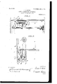
- Figure 1 is a horizontal view taken on a line immediately below the floor of the car, showing the safety mechanism and a portion of the hatchway.
- Fig. 2 is a vertical section as on line 2 2, Fig. 1.
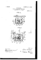
- Fig. 3 is a transverse section as on line 3 3, Fig. 2, showing the car below the door of the hatchway.
- Fig. 4 is a vertical section as on line 4 4, Fig. 2.
- Fig. 5 is a view similar to Fig. 3, showing the car locked at the door of the hatchway and the said door opened.
- A represents the elevator-car, and B the hatchway having sliding doors, as shown at B.
- a projection 6 upon the door B is engaged by the arm C of the bell-crank lever C, pivoted at 0 to the hatchway.
- a springD tends to hold the arm against the stop 0, as shown in Fig. 3.
- the arm C has a projection G which is acted upon by a cam-shoe E, carried by the car, which throws the bell-crank lever G into the position shown in Fig. 5 or in dotted lines, Fig. 3, thereby releasing the door.
- the cam-shoe E is carried by rods eand e, slidably mounted in bearings F, secured to the floor of the car.
- a spring G tends to hold the cam-shoe in the position shown in Fig. 3.
- a roller E is mounted on the camshoe E and acted uponby a cam H on a seg- -place of the hand-wheel.
- the rock-shaft I engages the cables 2' in the usual manner for starting and stopping the car.
- the cam H on the segment H will be out of engagement with the roller E, and the cam-shoe E will not be forced out, and it will therefore run past the floors without touching the projections C on the hatchway, as shown in Fig. 3.
- the cam H on the segment H will be shifted to the position shown in Fig. 5, which will force the roller E and the cam-shoe E out, so thatthe latter will engage the projection C and release the door.
- Carried by the cam-plate K is a block K, having a recess K formed therein, which engages the end of an arm L on the rock-shaft I, as shown in Fig. 5, and locks the rock-shaft, so that the car cannot be started until the door is closed, which will :force the lever J into the position shown in Fig. 3, which releases the cam-plate K and allows the spring Gr to withdraw said cam-plate and the block K, thereby releasing the arm L, so that the rock-shaft I can be shifted and release the roller E and allow the spring G to withdraw the cam-shoe E from the projection O and the bell-crank lever 0 to engage the projection b on the door and lock the same.
- the projection b on the door is provided with notches 7) to receive the end of the lever C, which will lock the door in case the same should not be entirely closed, and also to prevent the possibility of the door being closed to release the arm L and quickly opened again before the bell-crank lever G could engage the projection b to look the door.
Landscapes
- Engineering & Computer Science (AREA)
- Mechanical Engineering (AREA)
- Automation & Control Theory (AREA)
- Elevator Door Apparatuses (AREA)
Description
No. 809,076. v PATENTED JAN. 2, 1906.
I. B. BITTER. SAFETY DEVICE FOR ELEVATORS.
APPLICATION FILED JULY15,1905.
a $HEET$-SHEET 1.
J7 FIG/,1.
. lNVE/VTOR W/T/VESSES: I M ,3 m
, B} i I I PATENTED JAN. 2, 1906.
I. B. RITTER-Q SAFETY DEVICE FOR ELEVATORS.
APPLICATION FILED JULY 15, 1905.
3 SHEETS-SHEET 2.
[/VVE/VTGR l V/ T/VESSES:
N0. 809,076. PATENTED JAN. 2, 1906. I. B. BITTER.
SAFETY DEVICE FOR ELEVATORS.
APPLICATION FILED JULY 15. 1905.
3 SHEETS-SHEET 3.
Ha. k.
1 0 INVENTOR W 77%5555: W M 3 "mm W BX M 3f UNITED STATES PATENT OFFICE.
Specification of Letters Patent.
Patented Jan. 2, 1906.
Application filed July 15, 1905. Serial No. 269,193.
To all whom it may concern Be it known that I, IsAAc B. BITTER, a citizen of the United States, residing at Philadelphia. in the county of Philadelphia and State of Pennsylvania, have invented certain new and useful Improvements in Safety Devices for Elevators, of which the following is a specification.
My invention relates to improvements in a safety device for elevators.
The object of my invention is to construct a device which will lock the doors of the 'hatchway and unlock the same when the car is stopped at the floor-level.
A further object of my invention is to lock the mechanism for starting the car during the time the door remains open.
My invention as generally stated consists in the employment of locking-levers at the doors of thehatchway for locking the doors and mechanism upon the car to engage said levers to unlock the doors, also a lever which is thrown into action when said door is open to lock the operating mechanism of the car, together with various novel features of construction and organizations of parts, which will be hereinafter fully set forth and claimed.
In the drawings, Figure 1 is a horizontal view taken on a line immediately below the floor of the car, showing the safety mechanism and a portion of the hatchway. Fig. 2is a vertical section as on line 2 2, Fig. 1. Fig. 3 is a transverse section as on line 3 3, Fig. 2, showing the car below the door of the hatchway. Fig. 4 is a vertical section as on line 4 4, Fig. 2. Fig. 5 is a view similar to Fig. 3, showing the car locked at the door of the hatchway and the said door opened.
Referring to the drawings, A represents the elevator-car, and B the hatchway having sliding doors, as shown at B. A projection 6 upon the door B is engaged by the arm C of the bell-crank lever C, pivoted at 0 to the hatchway. A springD tends to hold the arm against the stop 0, as shown in Fig. 3. The arm C has a projection G which is acted upon by a cam-shoe E, carried by the car, which throws the bell-crank lever G into the position shown in Fig. 5 or in dotted lines, Fig. 3, thereby releasing the door.
The cam-shoe E is carried by rods eand e, slidably mounted in bearings F, secured to the floor of the car. A spring G tends to hold the cam-shoe in the position shown in Fig. 3. A roller E is mounted on the camshoe E and acted uponby a cam H on a seg- -place of the hand-wheel.
ment H on the rock-shaft I, controlled by the mechanism for starting and stopping the car,
consisting of a hand-wheel i, or a lever, as shown in dotted lines, Fig. 2, may be used in The rock-shaft I engages the cables 2' in the usual manner for starting and stopping the car. When the car is running, the cam H on the segment H will be out of engagement with the roller E, and the cam-shoe E will not be forced out, and it will therefore run past the floors without touching the projections C on the hatchway, as shown in Fig. 3. When the car is to be stopped at the floor, the cam H on the segment H will be shifted to the position shown in Fig. 5, which will force the roller E and the cam-shoe E out, so thatthe latter will engage the projection C and release the door.
' When the door is open, I lock the starting mechanism on the car in the following manner: The projection Z) on the door engages one arm of a lever J when the door is closed. When the door is open, the springD tends to draw the lever J into the position shown in Fig. 5. The lever J is provided with a projection J, which strikes a cam-plate K, carried by rods and Z6, slidably mounted in the bearings F on the car. The spring G tends to hold said cam-plate K drawn in toward the bearings F; but it has not sufficient strength to resist the action'of the spring D, which operates the lever J to force the cam-plate K into the position shown in Fig. 5. Carried by the cam-plate K is a block K, having a recess K formed therein, which engages the end of an arm L on the rock-shaft I, as shown in Fig. 5, and locks the rock-shaft, so that the car cannot be started until the door is closed, which will :force the lever J into the position shown in Fig. 3, which releases the cam-plate K and allows the spring Gr to withdraw said cam-plate and the block K, thereby releasing the arm L, so that the rock-shaft I can be shifted and release the roller E and allow the spring G to withdraw the cam-shoe E from the projection O and the bell-crank lever 0 to engage the projection b on the door and lock the same. The projection b on the door is provided with notches 7) to receive the end of the lever C, which will lock the door in case the same should not be entirely closed, and also to prevent the possibility of the door being closed to release the arm L and quickly opened again before the bell-crank lever G could engage the projection b to look the door.
Having thus described my invention, I claim and desire to secure by Letters Patent 1. The combination of an elevator-car, a door, a projection upon said door, a bell-crank lever pivoted to the hatchway and adapted to engage said projection, a lever pivoted to said hatchway adapted to be engaged by said projection when the door is closed, a cam-shoe upon said car adapted to engage said bell-crank lever and unlock the door, a cam-plate upon said car to be engaged by said lever when the door is open and means controlled by said cam-plate to lock the car, substantially as described.
2. The combination of an elevator-car, a door, aprojection upon said door, a bell-crank lever to engage said projection, a lever adapted to be held out of action by said projection when said door is closed, a bearing on said car, a cam-shoe slidably mounted in said bearing, means for throwing said cam-shoe into engagement with said bell-crank lever, a cam-plate slidably mounted in said bearing adapted to be acted upon by said lever when said door is open and lock the car, substantially as described.
3. The combination of an elevator-car, a door, a projection upon said door, a bell-crank lever to engage said projection, a lever adapted to be held out of action by said projection, a bearing upon said car, a cam-shoe slidably mounted in said bearing, a rock-shaft, a cam upon the same adapted to throw said camshoe into engagement with said bell-crank lever and release said door, a cam-plate slidably mounted in said bearing adapted to be acted upon by said lever when the door is open, an arm on said rock-shaft to be engaged by said cam-plate and means for operating said rock-shaft in conjunction with the mechanism for starting and stopping the car, substantially as described.
L. The combination of an elevator-car, a rock-shaft to control said car, a cam on said rock-shaft, a roller, a cam-shoe carrying said roller, a bearing, an arm on saidrock-shaft,
a block to engage saidarm, a cam-plate carrying said block, a spring between said camplate and said cam-shoe, and levers upon the hatchway to coact with said cam-plate and said cam-shoe, substantially as described.
5. The combination of an elevator-car, a rock-shaft to control said car, a cam on said rock-shaft, a roller, a cam-shoe, rods carrying said cam-shoe, bearings in which said rods are mounted, a spring, a bell-crank lever on the hatchway, a projection on the same to be engaged by said cam-shoe, and a door having a projection thereon, adapted to be engaged by said bell -crank lever, substantially as described.
6. The combination of an elevator-car, a rock-shaft, an arm on the same, a block having a recess formed therein, a cam-plate carrying said block, rods carrying said camplate, bearings in which said rods are mount-' ed, a lever pivoted to the Wall of the hatchway, a door, a projection upon the door to hold said lever out of action, and a projection upon the said lever to engage said cam-plate when the door is opened, substantially as clescribed.
7 The combination of an elevator-car, a door, a projection on said door, said projection having a plurality of notches formed therein, a bell-crank lever, a projection on the same, a lever engaged by the said projection upon the door, a spring, a projection on said lever, and means upon the car to control said bell-crank lever and release the door and to lock the car when acted upon by the said lever controlled by the projection on the door, substantially as described.
In testimony whereof'I aifix my signature in presence of two witnesses.
' ISAAC B. BITTER.
I/Vitnesses:
JOSEPH T. TAYLOR, M. R. OLEoLAND.
Priority Applications (1)
| Application Number | Priority Date | Filing Date | Title |
|---|---|---|---|
| US26979305A US809076A (en) | 1905-07-15 | 1905-07-15 | Safety device for elevators. |
Applications Claiming Priority (1)
| Application Number | Priority Date | Filing Date | Title |
|---|---|---|---|
| US26979305A US809076A (en) | 1905-07-15 | 1905-07-15 | Safety device for elevators. |
Publications (1)
| Publication Number | Publication Date |
|---|---|
| US809076A true US809076A (en) | 1906-01-02 |
Family
ID=2877557
Family Applications (1)
| Application Number | Title | Priority Date | Filing Date |
|---|---|---|---|
| US26979305A Expired - Lifetime US809076A (en) | 1905-07-15 | 1905-07-15 | Safety device for elevators. |
Country Status (1)
| Country | Link |
|---|---|
| US (1) | US809076A (en) |
-
1905
- 1905-07-15 US US26979305A patent/US809076A/en not_active Expired - Lifetime
Similar Documents
| Publication | Publication Date | Title |
|---|---|---|
| US809076A (en) | Safety device for elevators. | |
| US1223157A (en) | Elevator-door-locking mechanism. | |
| US778551A (en) | Elevator-lock. | |
| US582987A (en) | Island | |
| US1381262A (en) | Locking mechanism for elevator-doors | |
| US940792A (en) | Automatic safety device for elevators. | |
| US995654A (en) | Safety device for elevators. | |
| US583332A (en) | muckle | |
| US401273A (en) | Elevator-hatch way | |
| US1188752A (en) | Mine-gate lock. | |
| US595961A (en) | Elevator locking mechanism | |
| US398699A (en) | Elevator | |
| US838213A (en) | Safety device for elevators. | |
| US837323A (en) | Safety device for elevators. | |
| US702373A (en) | Locking device for elevators. | |
| US555825A (en) | Sylvania | |
| US640859A (en) | Elevator. | |
| US1221543A (en) | Elevator protective apparatus. | |
| US560645A (en) | Safety device for elevators | |
| US762455A (en) | Lock for elevator-doors. | |
| US693936A (en) | Safety device for elevators. | |
| US783731A (en) | Door-lock. | |
| US870589A (en) | Elevator-lock. | |
| US579072A (en) | John s | |
| US579071A (en) | muckle |