US809072A - Steering device for boats. - Google Patents
Steering device for boats. Download PDFInfo
- Publication number
- US809072A US809072A US25002605A US1905250026A US809072A US 809072 A US809072 A US 809072A US 25002605 A US25002605 A US 25002605A US 1905250026 A US1905250026 A US 1905250026A US 809072 A US809072 A US 809072A
- Authority
- US
- United States
- Prior art keywords
- sprocket
- chain
- steering device
- boats
- rudder
- Prior art date
- Legal status (The legal status is an assumption and is not a legal conclusion. Google has not performed a legal analysis and makes no representation as to the accuracy of the status listed.)
- Expired - Lifetime
Links
- 238000010276 construction Methods 0.000 description 4
- 238000004804 winding Methods 0.000 description 2
Images

Classifications
-
- B—PERFORMING OPERATIONS; TRANSPORTING
- B63—SHIPS OR OTHER WATERBORNE VESSELS; RELATED EQUIPMENT
- B63H—MARINE PROPULSION OR STEERING
- B63H25/00—Steering; Slowing-down otherwise than by use of propulsive elements; Dynamic anchoring, i.e. positioning vessels by means of main or auxiliary propulsive elements
- B63H25/06—Steering by rudders
- B63H25/08—Steering gear
- B63H25/10—Steering gear with mechanical transmission
Definitions
- My invention consists of a new and useful steering device for boats wherein I provide direct action upon the tiller and dispense with the usual winding of the tiller rope or chain upon a drum.
- Figure 1 represents a sectional View on line w m, Fig. 2, of a steering device embodying my invention.
- Fig. 2 represents a plan view thereof.
- Fig. 3 represents a sectional view on line y y, Fig. 1.
- Fig. 1 represents a plan View of a boat, showing the device in position thereon.
- Fig. 5 represents a plan view show ing a portion of the device in detached position.
- 1 designates a plate provided with suitable openings for the reception of screws 2, whereby the plate and I device are secured in proper position upon the boat.
- 3 designates a shaft secured to said plate, upon which is mounted a sprocket-wheel 4, said sprocket being in suitable connection with the hand or steering wheel 5, in the present instance by means of the sleeve 6.
- 7 and 8 designate pins which are mounted on said plate 1. Mounted upon said pins are loose pulleys or sheaves 9, which are adapted to rotate in the same plane as that of the sprocket, the peripheries of which are provided with the grooves 10, as will be seen from Fig.
- said pulleys being situated adjacent the wheel l and slightly below the same, but in such a position with respect thereto that the teeth of the sprocket pass into the grooves of each of said pulleys, whereby the latter serve not only to positively insure that the chain is properly directed or guided to the sprocket, but also serve as guards on each side of said sprocket to prevent the chain from leaving the same or from being twisted or fouled.
- 11 designates a chain which is in suitable connection with the rudder or tiller of the boat and which is passed around the pulleys and is in" engagement with the teeth of the sprocket-wheel4.
- the chain as above stated, may be connected with the rudder in any suitable manner.
- I have shown one means of connection, wherein 12 designates the boat to which the steering device is secured and which is provided with a rudder 13.
- the rudder can be operated in either direction by turning the wheel 5, which rotates the gear 4 and carries with it the chain 11, which is movable in either direction, depending upon the movement of the wheel 5, and the boat is thus guided.
- a sprocket rotatably mounted, a chain in engagement therewith and in suitable connection with the rudder and means situated adjacent said sprocket serving both to properly guide the chain thereto and to act as guards for preventing the chain from leaving said sprocket, whereby fouling is prevented.
- a sprocket rotatably mounted, a chain in engagement therewith and in suitable connection with the rudder and pulleys situated adjacent said sprocket serving to properly guide the chain thereto and to act as guards to prevent the chain from leaving said sprocket.
- a sprocket rotatably mounted on a frame, a chain in engagement therewith and in suitable connection with a rudder, and pulleys mounted on the frame and so located with respect to said sprocket that the teeth thereof pass into the grooves of said pulley whereby said pulleys serve both to properly guide the chain to said sprocket, and prevent the same from leaving said sprocket.
- a sprocket rotatably mounted, a chain in engagement therewith and in suitable connection with a rudder, pulleys mounted adjacent 10 said sprocket and having grooves in their periphery into which the teeth of said sprocket are adapted to pass, whereby the said pulleys serve both to guide the chain and to prevent the same from leaving said sprocket and means for operating the said sprocket.
Landscapes
- Chemical & Material Sciences (AREA)
- Engineering & Computer Science (AREA)
- Combustion & Propulsion (AREA)
- Mechanical Engineering (AREA)
- Ocean & Marine Engineering (AREA)
- Soil Working Implements (AREA)
Description
7 PATENTED JAN. 2, 1906. A. B. MuCOY.
STEERING DEVICE FOR BOATS.
APPLICATION FILED MAR.14, 1905.
2 SHEETSSHBET 1. 19 v 44 @21 5 @T /c y 7 I I 35114 M No. 809,072. PATENTED JAN. 2, 1906.
' A. B. MOODY.
STEERING DEVICE FOR BOATS. APPLIOATION FILED MAR.14,1905.
2 SHEETS-SHEET Z.
gnoanroz $511 if I izuqr m,
UNITED STATES PATENT OFFICE.
ALONZO BURR MCCOY, OF BURLINGTON, NEW JERSEY.
STEERING DEVICE FOR BOATS.
Specification of Letters Patent.
Patented Jan. 2, 1906.
Application filed March 14-, 1905. Serial No. 250,026.
To all whom, it may concern:
Be it known that I, ALoNzo BURR MoCoY, a citizen of the United States, residing at Burlington, in the county of Burlington, State of New Jersey, have invented a new and useful Steering Device for Boats, of which the following is a specification.
My invention consists of a new and useful steering device for boats wherein I provide direct action upon the tiller and dispense with the usual winding of the tiller rope or chain upon a drum.
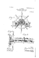
Figure 1 represents a sectional View on line w m, Fig. 2, of a steering device embodying my invention. Fig. 2 represents a plan view thereof. Fig. 3 represents a sectional view on line y y, Fig. 1. Fig. 1 represents a plan View of a boat, showing the device in position thereon. Fig. 5 represents a plan view show ing a portion of the device in detached position.
Similar numerals of reference indicate corresponding parts in the figures.
Referring to the drawings, 1 designates a plate provided with suitable openings for the reception of screws 2, whereby the plate and I device are secured in proper position upon the boat. 3 designates a shaft secured to said plate, upon which is mounted a sprocket-wheel 4, said sprocket being in suitable connection with the hand or steering wheel 5, in the present instance by means of the sleeve 6. 7 and 8 designate pins which are mounted on said plate 1. Mounted upon said pins are loose pulleys or sheaves 9, which are adapted to rotate in the same plane as that of the sprocket, the peripheries of which are provided with the grooves 10, as will be seen from Fig. 2, said pulleys being situated adjacent the wheel l and slightly below the same, but in such a position with respect thereto that the teeth of the sprocket pass into the grooves of each of said pulleys, whereby the latter serve not only to positively insure that the chain is properly directed or guided to the sprocket, but also serve as guards on each side of said sprocket to prevent the chain from leaving the same or from being twisted or fouled.
11 designates a chain which is in suitable connection with the rudder or tiller of the boat and which is passed around the pulleys and is in" engagement with the teeth of the sprocket-wheel4. The chain, as above stated, may be connected with the rudder in any suitable manner. In the drawings I have shown one means of connection, wherein 12 designates the boat to which the steering device is secured and which is provided with a rudder 13. Connected with the chain 11 at each end thereof, in the present instance by means of swivels 14:, are the ropes 15, which pass around the pulleys 16 on each side of the boat and through suitable guides 17 and are connected with the rudder, whereby it will be seen that by movement of the chain the ropes on either side may be operated in the required direction in order to turn the rudder.
The operation will be readily seen. By means of my construction the rudder can be operated in either direction by turning the wheel 5, which rotates the gear 4 and carries with it the chain 11, which is movable in either direction, depending upon the movement of the wheel 5, and the boat is thus guided.
It will be evident that the chain passes directly from the rudder on each side and around the pulleys 9 and over or under the gear 4:, and by reason of this construction fouling of the tiller-guides is prevented, since there is no winding upon a drum, as is usually the case and in which the tiller rope or chain often becomes tangled and the boat thus becomes unmanageable.
It will be evident that various changes may be made in the details of construction shown, and I do not, therefore, desire to be limited in every instance to the exact construction shown and described.
Having thus described my invention, what I claim as new, and desire to secure by Letters Patent, is
1. In a device of the character described, a sprocket rotatably mounted, a chain in engagement therewith and in suitable connection with the rudder and means situated adjacent said sprocket serving both to properly guide the chain thereto and to act as guards for preventing the chain from leaving said sprocket, whereby fouling is prevented.
2. In a device of the character described, a sprocket rotatably mounted, a chain in engagement therewith and in suitable connection with the rudder and pulleys situated adjacent said sprocket serving to properly guide the chain thereto and to act as guards to prevent the chain from leaving said sprocket.
3. In a device of the character described, a sprocket rotatably mounted on a frame, a chain in engagement therewith and in suitable connection with a rudder, and pulleys mounted on the frame and so located with respect to said sprocket that the teeth thereof pass into the grooves of said pulley whereby said pulleys serve both to properly guide the chain to said sprocket, and prevent the same from leaving said sprocket.
4. In a device of the character described, a sprocket rotatably mounted, a chain in engagement therewith and in suitable connection with a rudder, pulleys mounted adjacent 10 said sprocket and having grooves in their periphery into which the teeth of said sprocket are adapted to pass, whereby the said pulleys serve both to guide the chain and to prevent the same from leaving said sprocket and means for operating the said sprocket.
WASHINGTON I. IRWIN, J. LEEDOM SMITH.
Priority Applications (1)
| Application Number | Priority Date | Filing Date | Title |
|---|---|---|---|
| US25002605A US809072A (en) | 1905-03-14 | 1905-03-14 | Steering device for boats. |
Applications Claiming Priority (1)
| Application Number | Priority Date | Filing Date | Title |
|---|---|---|---|
| US25002605A US809072A (en) | 1905-03-14 | 1905-03-14 | Steering device for boats. |
Publications (1)
| Publication Number | Publication Date |
|---|---|
| US809072A true US809072A (en) | 1906-01-02 |
Family
ID=2877553
Family Applications (1)
| Application Number | Title | Priority Date | Filing Date |
|---|---|---|---|
| US25002605A Expired - Lifetime US809072A (en) | 1905-03-14 | 1905-03-14 | Steering device for boats. |
Country Status (1)
| Country | Link |
|---|---|
| US (1) | US809072A (en) |
Cited By (1)
| Publication number | Priority date | Publication date | Assignee | Title |
|---|---|---|---|---|
| US4367881A (en) * | 1980-10-01 | 1983-01-11 | Outboard Marine Corporation | Vehicle steering system |
-
1905
- 1905-03-14 US US25002605A patent/US809072A/en not_active Expired - Lifetime
Cited By (1)
| Publication number | Priority date | Publication date | Assignee | Title |
|---|---|---|---|---|
| US4367881A (en) * | 1980-10-01 | 1983-01-11 | Outboard Marine Corporation | Vehicle steering system |
Similar Documents
| Publication | Publication Date | Title |
|---|---|---|
| US809072A (en) | Steering device for boats. | |
| US1403318A (en) | Steering gear | |
| US385856A (en) | Hoisting-tackle | |
| US951510A (en) | Chain-saw attachment. | |
| US977277A (en) | Towing-machine. | |
| US291765A (en) | Pentee | |
| US197501A (en) | Improvement in windlass and capstan attachments | |
| US841198A (en) | Hoisting-machine. | |
| US540997A (en) | Gold-mining device | |
| US5284A (en) | Steering apparatus for vessels | |
| US1003353A (en) | Continuous engine-plowing with two engines. | |
| US892325A (en) | Variable-speed and reversing mechanism. | |
| US428886A (en) | Means for translating power and motion of drive-shafts | |
| US274172A (en) | Steering mechanism for vessels | |
| US99900A (en) | Improved oyster-dredge windlass | |
| US1553062A (en) | Slewing gear for drag-line excavators, grab excavators, revolving shovels, and the like | |
| US311869A (en) | Apparatus | |
| US384309A (en) | Hubebt hope coedes | |
| US403598A (en) | Device for transmitting power | |
| US294670A (en) | Wire-reel | |
| US1213604A (en) | Sheaf-hoist. | |
| US143017A (en) | Improvement in steering apparatus | |
| US540745A (en) | Dredging or excavating machine | |
| US1141040A (en) | Cordage-rope machine. | |
| US405309A (en) | Driving means for thrashing-machines |