US809071A - Means for supporting the expansion ends of bridges, &c. - Google Patents
Means for supporting the expansion ends of bridges, &c. Download PDFInfo
- Publication number
- US809071A US809071A US25893305A US1905258933A US809071A US 809071 A US809071 A US 809071A US 25893305 A US25893305 A US 25893305A US 1905258933 A US1905258933 A US 1905258933A US 809071 A US809071 A US 809071A
- Authority
- US
- United States
- Prior art keywords
- rollers
- bearing members
- pair
- members
- bearing
- Prior art date
- Legal status (The legal status is an assumption and is not a legal conclusion. Google has not performed a legal analysis and makes no representation as to the accuracy of the status listed.)
- Expired - Lifetime
Links
- 230000003292 diminished effect Effects 0.000 description 9
- 238000005096 rolling process Methods 0.000 description 8
- 230000015572 biosynthetic process Effects 0.000 description 7
- 238000010276 construction Methods 0.000 description 4
- 230000008602 contraction Effects 0.000 description 2
- 239000000428 dust Substances 0.000 description 2
- 241000507564 Aplanes Species 0.000 description 1
- 230000002159 abnormal effect Effects 0.000 description 1
- 239000003818 cinder Substances 0.000 description 1
- 230000000694 effects Effects 0.000 description 1
- 230000004048 modification Effects 0.000 description 1
- 238000012986 modification Methods 0.000 description 1
- 239000002245 particle Substances 0.000 description 1
- 230000000284 resting effect Effects 0.000 description 1
- 239000007787 solid Substances 0.000 description 1
Images

Classifications
-
- E—FIXED CONSTRUCTIONS
- E01—CONSTRUCTION OF ROADS, RAILWAYS, OR BRIDGES
- E01D—CONSTRUCTION OF BRIDGES, ELEVATED ROADWAYS OR VIADUCTS; ASSEMBLY OF BRIDGES
- E01D19/00—Structural or constructional details of bridges
- E01D19/04—Bearings; Hinges
Definitions
- Patented J' an. 2, 1906.
- My invention relates particularly to the vroller-bearing means for accommodating and facilitating the movement of a part due to expansion or contraction; and it has for its object to maintain the nest of rollers constantly at right angles to the predominating line of movement of the part, also to prevent movement of the rollers without a commensurate movement of the part, and vice versa.
- the invention may be said, briefly, to consist of a device or a plurality of devices, preferably dowels, in combination with the bearing mem bers, between which are located a nest of rollers adapted to receive the concentrated pressure upon the bearing members, such device or devices being constructed and arranged to e"ect a sliding connection between the rollers and the said members.
- the purpose of this sliding connection is to correct a tendency of the rolling member influenced directly thereby to deviate from any position in which it is set, this being effected by the sliding connection constantly maintained between the bearing and rolling members.
- the invention may be said to consist of a pair of dowels carried by one of the bearing members and projecting into holes in one of the rollers near the opposite ends of the latter, the dowels and holes being preferably of circular cross-section and such dowels being of truncated conoidal formation and preferably cycloidal in their longitudinal direction.
- A'further feature of my invention consists of a dust-guard of particular construction and specially adapted for use in connection with roller-bearing mechanism above mentioned, and such dust-guard consists of an open frame inclosing the nest of rollers and'adapted to lie freely between the bearing members and make as close aseal as possible between them for the purpose of excluding foreign particles.
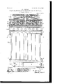
- FIG. 1 is a sectional view illustrating my invention applied to the pier members of a bridge, the view being taken on lineA A, Fig. 3.
- Fig. 2 is an elevation of the rollers and Iinclosing frame looking toward the ends of the rollers.
- Fig. 3 is aplan view with the rollerplate and the parts above it removed.
- Fig. 4 is a side elevation, partly invertical section, of the parts illustrated in Fig. 3.
- Fig. 5 is an enlarged sectional view of the middle roller of the nest and that on each side thereof' and my improved dowel.
- Fig. 1 is a sectional view illustrating my invention applied to the pier members of a bridge, the view being taken on lineA A
- Fig. 3 is an elevation of the rollers and Iinclosing frame looking toward the ends of the rollers.
- Fig. 3 is aplan view with the rollerplate and the parts above it removed.
- Fig. 4 is a side elevation, partly invertical section, of the
- FIG. 6 is an end elevation illustrating a modilied form of dust-guard.
- Fig. 7 is a sectional view taken on line B B, Fig. 8.
- Fig. 8 is a plan view of the embodiment of a portion of my improved bearing illustrated in Figs. 7 and 8.
- Fig. 9 is a vertical sectional view taken axially through the middle roller.
- Fig. 10 is a perspective sectional view of a modification of my improved dowel illustrated.
- roller-bed plate b, roller-plate o, and shoe-plate e are of the usual construction employed in bridge-building and will not be described in detail herein.
- rollers f are in the main of the usual solid cylindrical form.
- My improved devices for effecting a sliding connection between the rollers and bearing members on each side thereof (the roller-bed plate and roller-plate in this instance) consists of the following construction
- the middle roller preferably is formed with a pair of diametric holes g in the same axial plane relatively to the roller and located, preferably, one near each end thereof, and the roller-bed plate?? and roller-plate c are bored, as at tand ,re'- spectively.
- Two pairs of dowels j and la are set in the borings 71, and fr', the dowels j beingy preferably threaded into the borings L, which are tapped for the purpose, while the dowels It* are preferably of greater length and extend through holes in a disk (l, having a curved upper surface d and a flat under surface d2, the latter being adapted to rest in a recess in the top of the roller-plate c, while the shoeplate, resting upon the curved top OZ', is correspondingly curved to effect a universal joint.
- the dowels lo are secured in place by nuts m, screwed upon their upper ends, which are IOO IIO
- the shoe-plate is bored to accommodate the nuts, thereby effecting a connection between the shoeplate and the roller-bed plate through the medium of the dowel lathe roller with which they engage,and the dowelsj in the roller-bed plate and maintaining constantly the same relative transverse position of the pier members.
- the protruding portion of the dowels is of truncated conoidal form, the sides or perimeters 0 of each being preferably of cycloidal formation in their longitudinal direction, while their ends p are preferably rounded.
- the distance from center to center of the rollers and the dimensions of the dowels are preferably such that the cycloidal surface 0 at one side of thev perimeter of each dowel of the forward pair (the direction of movement of the rollers being considered) will impinge against the roller in advance thereof before the ends of such dowels leave the holes in the rollers, and the cycloidal surface at the opposite side of the perimeter of the other dowels will be impinged against by the roller following it.
- the rollers are -preferably positioned in this relation by two of the members of a dustguard, to be presently described. The construction as thus far described provides the means, before mentioned, for effecting a sliding contact between the rollers and bearing members.
- either the upper or lower pair of dowels can be dispensed with and the other pair will serve the purpose to advantage, or if the movement of a nest of bars or short rollers is to be governed a single dowel, whether of conoidal pin form or a plate of tapered cross-section with cycloidal inclined surfaces, as shown in Fig. 10, may be utilized.
- This dust-guard consists, preferably, of a rectangular frame composed of a pair of bars i2 of channel crosssection and a pair of flat bars 3, having their ends bent, as at 4, and bolted to the ends of the channel-bars 2, while the webs of the channel-bars and the ends of the rollers, and the channel-bars are formed with holes 10, each elongated in a longitudinal plane to allow of less than the maximum movement of the rollers with one of the bearing members without disturbing the frame.
- the dust-guard frame will accompany them.
- the length of the slots 5 is sufficient to accommodate anything but abnormal expansion and contraction, which is taken care of by the freedom of the guard to be displaced in either direction.
- the channelbars being slightly less in height than the distance between the bearing members and the said dust-guard being free to move independently ot' both bearing members.
Landscapes
- Engineering & Computer Science (AREA)
- Architecture (AREA)
- Civil Engineering (AREA)
- Structural Engineering (AREA)
- Rolls And Other Rotary Bodies (AREA)
Description
No. 000,071. PATBNTED- JAN. 2, v1900. P. B. MOTLEY.
MEANS EUR SUPPORTING THE EXPANSION ENDS OF BRIDGES, &c.
APlJLIcATIoN FILED MAY 5, 1905.
2 SHEETS-SHEET 1.
dfn"
S11/vento@ No. 809,071. PATENTED IAN. z, 1900.
' P. B. MOILEY. MEANS POE SUPPORTING IEE EXPANSION ENDS 0E BRIDGES, am.
l.LIPLIGA'IION FILED MAY 5. 1905.
2 SHEBTS-SHEET 2.
/757 4 ,e J' I/ l Elf-"LE E 'IP LE A-; "'IN 5 fc' f/ ,E
lvwe Moz UNITED sTATEs lPATENT oEEIoE.
PHILLIPS BATHURST MOTLEY, OF MONTREAL, CANADA.
MEANS FOR SUPPORTING THE EXPANSION ENDS OF BRIDGES, 81.0.
Patented J' an. 2, 1906.
Application iiled May 5, 1905. 'Serial No. 258.933.
To all whom t may concern:
Be it known that I, PHILLIPS BATHURST MOT- LEY, of thecity of Montreal, Province of Quebec, Canada, have invented certain new and useful Improvements in Means for Supporting the Expansion Ends of Bridges, Roofs, and the Like; and I do .hereby declare that the following' is a full, clear, and exact description of the same.
My invention relates particularly to the vroller-bearing means for accommodating and facilitating the movement of a part due to expansion or contraction; and it has for its object to maintain the nest of rollers constantly at right angles to the predominating line of movement of the part, also to prevent movement of the rollers without a commensurate movement of the part, and vice versa.
The invention may be said, briefly, to consist of a device or a plurality of devices, preferably dowels, in combination with the bearing mem bers, between which are located a nest of rollers adapted to receive the concentrated pressure upon the bearing members, such device or devices being constructed and arranged to e"ect a sliding connection between the rollers and the said members. The purpose of this sliding connection is to correct a tendency of the rolling member influenced directly thereby to deviate from any position in which it is set, this being effected by the sliding connection constantly maintained between the bearing and rolling members. g More speciiically speaking, the invention may be said to consist of a pair of dowels carried by one of the bearing members and projecting into holes in one of the rollers near the opposite ends of the latter, the dowels and holes being preferably of circular cross-section and such dowels being of truncated conoidal formation and preferably cycloidal in their longitudinal direction.
A'further feature of my invention consists of a dust-guard of particular construction and specially adapted for use in connection with roller-bearing mechanism above mentioned, and such dust-guard consists of an open frame inclosing the nest of rollers and'adapted to lie freely between the bearing members and make as close aseal as possible between them for the purpose of excluding foreign particles.
For full comprehension, however, of my invention reference must be had to the accompanying drawings, forming a part of this specilication, in which'similar reference characters indicate the same parts, and wherein- Figure 1 is a sectional view illustrating my invention applied to the pier members of a bridge, the view being taken on lineA A, Fig. 3. Fig. 2 is an elevation of the rollers and Iinclosing frame looking toward the ends of the rollers. Fig. 3 is aplan view with the rollerplate and the parts above it removed. Fig. 4 is a side elevation, partly invertical section, of the parts illustrated in Fig. 3. Fig. 5 is an enlarged sectional view of the middle roller of the nest and that on each side thereof' and my improved dowel. Fig. 6 is an end elevation illustrating a modilied form of dust-guard. Fig. 7 is a sectional view taken on line B B, Fig. 8. Fig. 8 is a plan view of the embodiment of a portion of my improved bearing illustrated in Figs. 7 and 8. Fig. 9 is a vertical sectional view taken axially through the middle roller. Fig. 10 is a perspective sectional view of a modification of my improved dowel illustrated.
In order that my invention may be clearly understood, I haveillustrated the same applied to the pier members of a bridge, although it ymay be applied to advantage in any structure requiring an antifriction-bearing with limited movement.
The roller-bed plate b, roller-plate o, and shoe-plate e are of the usual construction employed in bridge-building and will not be described in detail herein.
The nest of rollers f are in the main of the usual solid cylindrical form. My improved devices for effecting a sliding connection between the rollers and bearing members on each side thereof (the roller-bed plate and roller-plate in this instance) consists of the following construction The middle roller preferably is formed with a pair of diametric holes g in the same axial plane relatively to the roller and located, preferably, one near each end thereof, and the roller-bed plate?? and roller-plate c are bored, as at tand ,re'- spectively. Two pairs of dowels j and la are set in the borings 71, and fr', the dowels j beingy preferably threaded into the borings L, which are tapped for the purpose, while the dowels It* are preferably of greater length and extend through holes in a disk (l, having a curved upper surface d and a flat under surface d2, the latter being adapted to rest in a recess in the top of the roller-plate c, while the shoeplate, resting upon the curved top OZ', is correspondingly curved to effect a universal joint. The dowels lo are secured in place by nuts m, screwed upon their upper ends, which are IOO IIO
screw-threaded. The shoe-plate is bored to accommodate the nuts, thereby effecting a connection between the shoeplate and the roller-bed plate through the medium of the dowel lathe roller with which they engage,and the dowelsj in the roller-bed plate and maintaining constantly the same relative transverse position of the pier members. The protruding portion of the dowels is of truncated conoidal form, the sides or perimeters 0 of each being preferably of cycloidal formation in their longitudinal direction, while their ends p are preferably rounded. The distance from center to center of the rollers and the dimensions of the dowels are preferably such that the cycloidal surface 0 at one side of thev perimeter of each dowel of the forward pair (the direction of movement of the rollers being considered) will impinge against the roller in advance thereof before the ends of such dowels leave the holes in the rollers, and the cycloidal surface at the opposite side of the perimeter of the other dowels will be impinged against by the roller following it. The rollers are -preferably positioned in this relation by two of the members of a dustguard, to be presently described. The construction as thus far described provides the means, before mentioned, for effecting a sliding contact between the rollers and bearing members.
Under certain circumstances either the upper or lower pair of dowels can be dispensed with and the other pair will serve the purpose to advantage, or if the movement of a nest of bars or short rollers is to be governed a single dowel, whether of conoidal pin form or a plate of tapered cross-section with cycloidal inclined surfaces, as shown in Fig. 10, may be utilized.
It is a well-known fact that great damage to roller-bearings is due to the admission of dust, cinders, and the like thereto, which obstructs the movement of the rollers, and therefore destroys their efficiency. To obviate this, I have devised what may be termed a floating dust-guard adapted to completely encircle the nest of rollers. This dust-guard consists, preferably, of a rectangular frame composed of a pair of bars i2 of channel crosssection and a pair of flat bars 3, having their ends bent, as at 4, and bolted to the ends of the channel-bars 2, while the webs of the channel-bars and the ends of the rollers, and the channel-bars are formed with holes 10, each elongated in a longitudinal plane to allow of less than the maximum movement of the rollers with one of the bearing members without disturbing the frame. When one of the bearing members, and with it the rollers, move a greater distance in either direction than provided for by the slots 5 in the channel members of the frame, the dust-guard frame will accompany them. In the case of bridges the length of the slots 5 is sufficient to accommodate anything but abnormal expansion and contraction, which is taken care of by the freedom of the guard to be displaced in either direction.
.,What I claim is as follows:
l. The combination with a pair of bearing members, having a nest of rollers between them, of means effecting a sliding connection between such bearing members and rollers for the purpose of correcting any tendency of the rollers to deviate from any position with their aXes at right angles to their plane of travel.
2. The combination with a pair of bearing members, having a nest of rollers between them, of means effecting a sliding connection between such bearing members and rollers for the purpose of correcting anyI tendency of the rollers to deviate from any position with their axes at right angles to their plane of travel, and such means limiting' the extent of movement of such parts relatively to one another.
3. The combination with a pair of bearing members having a rolling member between them, of means carried by one of such members and effecting a sliding engagement with a member neXt to it for the purpose of maintaining the members constantly in the same relation.
4. The combination with a pair of bearing members having a rolling member between them, of means carried by one of such bearing members and effecting a sliding engagement with the rolling mem ber for the purpose of maintaining the members constantly in the same relation.
5. The combination with a pair of bearing members having a rolling member between them, one of such members having a hole therein presenting a face with which one of the faces of a projection carried by another of the members makes sliding contactfor the purpose of maintaining the members constantly in the same relation.
6. The combination with a pair of bearing members having a rolling member between them, one of such members having a hole therein presenting a face with which one of the faces of a projection carried by another of the members makes sliding contact for the purpose of maintaining the members constantly in the same relation. one of such faces being of cycloidal formation.
7. The combination with a pair of bearing IOO IIO
members having a rolling member between them, one of such members having a hole therein presentinga face with which one of the faces of a projection carried by another of the members makes sliding contact for the purpose of maintaining the members constantly in the same relation, the contacting face of the projection being of cycloidal Jformation.
8. The combination with a pair of bearing members having a nest of rollers between them, and means for spacing such rollers, of a device carried by one of the bearing members and presenting a face adapted to make sliding contact with the face presented by one of the walls of a hole in the perimeter of one of the rollers for the purpose of maintaining the bearing members and rollers constantly in the same relation.
9. The combination with a pair of bearing members having a nest of rollers between them, and means for spacing such rollers, of a device carried by one of the bearing members and presenting a face adapted to make sliding contact with the face presented by one of the walls of a hole in the perimeter of one of the rollers for the purpose of maintaining' the bearing members and rollers constantly in the same relation, one of such faces being of cycloidal formation.
10. The combination with a pair of bearing members having a nest of rollers between them, and means for spacing such rollers, of a device carried by one of the bearing members and presenting a face adapted to make sliding contact with the face presented by one of the walls of a hole in the perimeter of one of the rollers for the purpose of maintaining the bearing members and rollers constantly in the same relation, the contacting face of the device being of cycloidal formation.
11. The combination with a pair of bearing members, having a nest of rollers between them one of such rollers having a pair of holes in the perimeter thereof one near each end, and means for spacing such rollers, of a pair of conoidal dowels carried by one of the bearing members and projecting into'the holes in the roller.
12. The combination with a pair of bearing members, having a nest of rollers between them one of such rollers having a pair of holes in the perimeter thereof one near each end, and means for spacing such rollers, of a pair of dowels carried by one of the bearing members and projectinginto the holes in the roller, such dowels being of conoidal formation and cycloidal in axial direction.
13. rEhe combination with a pair of bearing members, having a nest of rollers between them one of such rollers having a pair of holes extending diametrically therethrough one near each end, and means for spacing such rollers, of a pair of conoidal dowels carried by one of the bearing members and projecting into the adjacent ends of the holes in the roller,
and a second pair of dowels carried by the other bearing member and projecting into the opposite ends of the holes.
14C. The combination with a pair of bearing members, having a nest of rollers between them one of such rollers havinga pair of holes extending diametrically therethrough one near each end, and means for spacing such rollers, of a pair of dowels carried by one of the bearing members and projecting into the adjacent ends of the holes in the roller, and a second pair of dowels carried by the other bearing members and projecting into the opposite ends of the holes, such dowels being of conoidal formation and cycloidal in axial direction.
15. The combination with a pair of bearing members having a roller bearing between them, of a dust-guard fitting closely between the bearing members and encircling the rollerbearing, one of the bearing members being movable relatively to the dust-guard, and the said dust-guard being free to move independently of both bearing members.
16. The combination with a pair of bearing members having a roller bearing between them, of a rectangular dust guard fitting closely between the bearing members and encircling the roller-bearing, one of the bearing members being movable relatively to the dustguard and the said dust-guard being free to move independently of both bearing members.
17. The combination with a pair of bearing members having a rollerbearing between them, of a rectangular dust-guard free of and fitting closely between the bearing members and encircling the roller-bearing, such dustguard consisting of a pair of parallel bars of channel cross-section, and a pair of bars having their ends secured rigidly to the ends of the channel-bars, such bars being slightly less in height than the distance between the bearing members.
18. The combination with a pair of bearing members having between them a nest of rollers with their ends diminished, of a rectangular dust-guard free of and fitting closely between the bearing members and encircling the rollers, such dust-guard consisting of a pair of parallel bars of channel cross-section formed with openings through which the diminished ends of the rollers project, and a pair of fiat bars having their ends bent at right angles and secured rigidly to the ends of the channel-bars, such bars being slightly less in height than the distance between the bearing members.
19. The combination with a pair of bearing members having between them a nest of rollers with their ends diminished, of a dust-guard fitting closely between the bearing members and consisting of a pair of parallel bars of channel cross section formed with holes through which the diminished ends of the rollers project, such holes being of suflicient IOO ISO
dimensions to allow of limited play of the guard between the bearing members, and means securing the bars against axial movement relatively to the rollers, the channelbars being slightly less in height than the distance between the bearing members and the said dust-guard being free to move independently ot' both bearing members.
20. The combination with a pair of bearing members having, between them, a nest of rollers with their ends diminished, of a rectangular dust-guard free of and fitting closely between the bearing members and encircling the rollers such dust-guard consisting of a pair of parallel bars oi' channel cross-section `formed with holes through which the diminished ends ot' the rollers project such holes being of sui'- icient dimensions to allow of limited play of the guard between the bearing members and a pair of bars having their ends secured rigidly to the ends of the channel-bars, such bars being slightly less in heightthan the distance between the bearing members.
21. The combination with a pair of bearing members having, between them, a nest of rollers with their ends diminished, of spacer-bars at the opposite ends of the rollers and having holes iittingclosely upon the diminished ends of the rollers, a rectangular dust-guard free of and iitting closely between the bearing members and encircling the rollers and the spacer-bars, such dust-guard consisting of a pair of parallel bars of channel cross-section formed with longitudinalslots, through which the diminished ends of the rollers project, and a pair of bars having their ends secured rigidly to the ends oi' the slotted bars, such bars being slightly less in height than the distance between the bearing members. l
In testimony whereofI have signed my name to this specification in the presence of two subscribing witnesses.
PHILLIPS BATHURS'I llIO'lLEY.
Witnesses:
WILLIAM P. MCFEAT, FRED. J. SEARS.
Priority Applications (1)
| Application Number | Priority Date | Filing Date | Title |
|---|---|---|---|
| US25893305A US809071A (en) | 1905-05-05 | 1905-05-05 | Means for supporting the expansion ends of bridges, &c. |
Applications Claiming Priority (1)
| Application Number | Priority Date | Filing Date | Title |
|---|---|---|---|
| US25893305A US809071A (en) | 1905-05-05 | 1905-05-05 | Means for supporting the expansion ends of bridges, &c. |
Publications (1)
| Publication Number | Publication Date |
|---|---|
| US809071A true US809071A (en) | 1906-01-02 |
Family
ID=2877552
Family Applications (1)
| Application Number | Title | Priority Date | Filing Date |
|---|---|---|---|
| US25893305A Expired - Lifetime US809071A (en) | 1905-05-05 | 1905-05-05 | Means for supporting the expansion ends of bridges, &c. |
Country Status (1)
| Country | Link |
|---|---|
| US (1) | US809071A (en) |
Cited By (4)
| Publication number | Priority date | Publication date | Assignee | Title |
|---|---|---|---|---|
| US3325842A (en) * | 1964-11-05 | 1967-06-20 | Spencer Geoffrey Dennis | Bridge bearings |
| US3806975A (en) * | 1970-04-13 | 1974-04-30 | Elastometal Ltd | Structural bearings |
| US3979787A (en) * | 1971-10-08 | 1976-09-14 | Ahlgren Nils H | Method of supporting bridge structures and like heavy-weight rigid structures upon displacement thereof |
| CN106087717A (en) * | 2016-06-28 | 2016-11-09 | 杜桂菊 | Bridge antidumping bearing |
-
1905
- 1905-05-05 US US25893305A patent/US809071A/en not_active Expired - Lifetime
Cited By (5)
| Publication number | Priority date | Publication date | Assignee | Title |
|---|---|---|---|---|
| US3325842A (en) * | 1964-11-05 | 1967-06-20 | Spencer Geoffrey Dennis | Bridge bearings |
| US3806975A (en) * | 1970-04-13 | 1974-04-30 | Elastometal Ltd | Structural bearings |
| US3979787A (en) * | 1971-10-08 | 1976-09-14 | Ahlgren Nils H | Method of supporting bridge structures and like heavy-weight rigid structures upon displacement thereof |
| CN106087717A (en) * | 2016-06-28 | 2016-11-09 | 杜桂菊 | Bridge antidumping bearing |
| CN106087717B (en) * | 2016-06-28 | 2017-12-15 | 孙新迪 | Bridge antidumping bearing |
Similar Documents
| Publication | Publication Date | Title |
|---|---|---|
| US809071A (en) | Means for supporting the expansion ends of bridges, &c. | |
| US1139543A (en) | Side bearing for railway-cars. | |
| US438576A (en) | Anti-friction journal-bearing | |
| US979120A (en) | Antifriction-bearing. | |
| US710673A (en) | Roller side bearing for cars. | |
| US484971A (en) | Expansion-bearing for bridges | |
| US741756A (en) | Journal-bearing. | |
| US432950A (en) | Thomas b | |
| US1044847A (en) | Roller-bearing device for car-trucks. | |
| US849914A (en) | Grate. | |
| US1167390A (en) | Rail-joint. | |
| US555346A (en) | Bearing for rock-shafts | |
| US935893A (en) | Roller side bearing. | |
| US694461A (en) | Side bearing for railway-cars. | |
| US1009575A (en) | Rail-joint. | |
| US921689A (en) | Rail-joint. | |
| US747125A (en) | Rail-joint. | |
| US1029054A (en) | Rail-joint. | |
| US1147433A (en) | Roller-bearing. | |
| US695849A (en) | Roller side bearing. | |
| US841937A (en) | Roller-bearing. | |
| US572236A (en) | Journal-bearing | |
| US1056525A (en) | Car wheel and axle. | |
| US666570A (en) | Journal-bearing. | |
| US784002A (en) | Roller-bearing. |