US8089659B2 - 4+ color management for gamut extension using a virtual CMYK methodology - Google Patents
4+ color management for gamut extension using a virtual CMYK methodology Download PDFInfo
- Publication number
- US8089659B2 US8089659B2 US12/463,469 US46346909A US8089659B2 US 8089659 B2 US8089659 B2 US 8089659B2 US 46346909 A US46346909 A US 46346909A US 8089659 B2 US8089659 B2 US 8089659B2
- Authority
- US
- United States
- Prior art keywords
- color
- colors
- printer
- virtual
- model
- Prior art date
- Legal status (The legal status is an assumption and is not a legal conclusion. Google has not performed a legal analysis and makes no representation as to the accuracy of the status listed.)
- Expired - Fee Related, expires
Links
- 238000000034 method Methods 0.000 title claims abstract description 32
- 239000003086 colorant Substances 0.000 claims abstract description 185
- 238000013507 mapping Methods 0.000 claims abstract description 38
- 238000012545 processing Methods 0.000 claims abstract description 23
- 230000008569 process Effects 0.000 claims abstract description 10
- 238000007726 management method Methods 0.000 claims description 44
- 238000009499 grossing Methods 0.000 claims description 22
- 238000004148 unit process Methods 0.000 claims description 2
- 238000007639 printing Methods 0.000 abstract description 20
- 238000009877 rendering Methods 0.000 abstract description 2
- 238000004891 communication Methods 0.000 description 5
- 238000006467 substitution reaction Methods 0.000 description 5
- 238000010586 diagram Methods 0.000 description 4
- 230000006870 function Effects 0.000 description 4
- 239000001061 orange colorant Substances 0.000 description 3
- 238000005070 sampling Methods 0.000 description 3
- 230000003068 static effect Effects 0.000 description 3
- 238000013461 design Methods 0.000 description 2
- 238000011161 development Methods 0.000 description 2
- 238000005516 engineering process Methods 0.000 description 2
- 238000012986 modification Methods 0.000 description 2
- 230000004048 modification Effects 0.000 description 2
- 230000003287 optical effect Effects 0.000 description 2
- 238000000926 separation method Methods 0.000 description 2
- 230000007704 transition Effects 0.000 description 2
- 238000013459 approach Methods 0.000 description 1
- 230000008901 benefit Effects 0.000 description 1
- 230000000694 effects Effects 0.000 description 1
- 238000013213 extrapolation Methods 0.000 description 1
- 230000002093 peripheral effect Effects 0.000 description 1
- 238000003672 processing method Methods 0.000 description 1
- 230000004044 response Effects 0.000 description 1
- 230000000717 retained effect Effects 0.000 description 1
- 238000000638 solvent extraction Methods 0.000 description 1
- 230000003595 spectral effect Effects 0.000 description 1
- 238000012549 training Methods 0.000 description 1
Images


Classifications
-
- H—ELECTRICITY
- H04—ELECTRIC COMMUNICATION TECHNIQUE
- H04N—PICTORIAL COMMUNICATION, e.g. TELEVISION
- H04N1/00—Scanning, transmission or reproduction of documents or the like, e.g. facsimile transmission; Details thereof
- H04N1/46—Colour picture communication systems
- H04N1/56—Processing of colour picture signals
- H04N1/60—Colour correction or control
- H04N1/6058—Reduction of colour to a range of reproducible colours, e.g. to ink- reproducible colour gamut
-
- H—ELECTRICITY
- H04—ELECTRIC COMMUNICATION TECHNIQUE
- H04N—PICTORIAL COMMUNICATION, e.g. TELEVISION
- H04N1/00—Scanning, transmission or reproduction of documents or the like, e.g. facsimile transmission; Details thereof
- H04N1/46—Colour picture communication systems
- H04N1/54—Conversion of colour picture signals to a plurality of signals some of which represent particular mixed colours, e.g. for textile printing
Definitions
- CMYK cyan, magenta, yellow and black
- Conventional 4-color CMYK (cyan, magenta, yellow and black) color systems used for processing a color model attempt to accommodate a well defined source color input, interpret the source color input in terms of an intermediary color space, such as the L*a*b* color space, and map the color through the color space to a realizable destination color based on characteristics of the printer.
- An example of this process is shown in FIG. 1 .
- the mapping from the realizable destination color to the L*a*b* color system and then to the source color is called the “forward printer model” because it is based on measured and modeled characteristics of the printer and knowledge of the source profile.
- the mapping from the requested source color to the destination color requires the opposite mapping, and is therefore called the “inverse printer model,” as shown in FIG. 1 .
- Machines that employ more than four colors have greater levels of redundancy and may require new tools of greater complexity. Developing such a complex tool is a significant investment in resources, likely to require a substantial effort over an extended period. To use the tool properly, thorough documentation and training sessions would be required as well.
- existing 4-color tools are leveraged to solve N-color management tasks, where N>4. This is achieved by solving what appears to be a succession of 4-color problems.
- 4-color tools are used to construct a 4-color model, where these 4 colors are a subset of the existing N colors supported by the system. This solution is used as a seed which can be grown to solve the N-color problem.
- we solve a subsequent 5-color problem This is accomplished by exploiting the inverse of this first color model to reduce the dimensionality of the first solution from 4 to 3. In this way, the 5-color problem can be made to appear like a 4-color task, and solved leveraging 4-color tools to construct a second color model.
- This deception is referred to as a virtual CMYK methodology.
- the inverse of the second color model can be exploited to reduce the dimensionality of the second solution from 5 to 3.
- received information of at least five colors is processed first using four colors of the at least five colors by a 4-color tool.
- the inverse of the first color model provides a mapping from three virtual source colors to four printer colors. This mapping is a useful summary of a larger number of real output printer colors in the form of fewer virtual input colors. It enables 4-color tools to solve color management problems for systems that support an arbitrary large number of supported output colors.
- the three virtual input colors and one of the unprocessed colors of the at least five colors are processed using the 4-color tool.
- one printer colorant may be retained and the other three output colorants may be interpreted as the previously exploited virtual colors.
- the inverse mapping from the first color model is used to map these three virtual colors back into four real printer colorants, yielding a total of five defined output printer colors.
- the resulting 5-color solution is the starting position required to fold in another candidate input color.
- each 4-color solution step brings one additional color separation into the model.
- the apparatus includes a printer model calculating unit that obtains and processes color information of at least five colors, a color replacing unit that maps the three virtual colors into four printer colors, and a controller that outputs at least five colors processed.
- the printer model calculating unit processes four of the at least five colors.
- the color replacing unit then maps the three virtual colors into five printer colors.
- the printer model calculating unit then processes the three virtual colors and one of unprocessed colors of the at least five colors.
- mapping from three virtual colors into four or more printer colors may be smoothened.
- the four colors for processing may include colors of CMYYK.
- FIG. 1 is a diagram showing an image processing scheme using an inverse printer model (IPM) and a forward printer model (FPM);
- IPM inverse printer model
- FPM forward printer model
- FIGS. 2 a and 2 b show mapping of a processed printer C 1 M 1 Y 1 O 1 gamut
- FIG. 3 shows mapping of a processed printer C 1 M 1 Y 1 O 1 V 2 gamut
- FIG. 4 shows mapping of a processed printer C 1 M 1 Y 1 O 1 V 2 K 3 gamut
- FIG. 5 is a flowchart showing processes of 4+ color management.
- FIG. 6 is a block diagram showing a 4+ color management device.
- a source color space e.g. GRACoL C G M G Y G
- 4+ printer colors e.g., CMYKOV
- the inverse of the first 4-color printer model provides a mapping from three source colors (e.g. GRACoL C G M G Y G ) to four printer colors C 1 M 1 Y 1 O 1 . This mapping allows these three source colors to be exploited as a surrogate for the four printer colors. This substitution of a smaller number of virtual colors for printer colors is a useful aspect of the features of the disclosure.
- the three source colors used need not be selected from a traditional source color standard, such as GRACol.
- the gamut spanned by the source colors is made sufficiently large as to cover the entire N-color printer gamut. This may guarantee the entire printer gamut will beutilized.
- the 3-color source and another unprocessed color (e.g., V) of the next one of the 4+ printer colors is processed to build a second 4-color model.
- the processed second four colors are mapped using the second printer model to four printer colors.
- three of these printer colors may be actually interpreted as virtual colors (e.g., C G M G Y G ), which are a surrogate for four real printer colors using the inverse of the first printer model.
- the printing machine includes, but is not limited to, a printer, copier, fax machine and any other printing device that may be suitable for using the exemplary embodiment according to the disclosure. It should be appreciated that the various embodiments are not limited to the use of four colors but may use less than four color tools.
- An extension of this technology includes the use of a mature tool that uses RGB (alternatively YCrCb or L*a*b*) source color to build 4+ printer color models using a similar virtual RGB (alternatively YCrCb or L*a*b*) methodology.
- RGB alternatively YCrCb or L*a*b*
- repeated mapping of source space colors with a dimensionality of at least three, to output printer colors may be used.
- FIG. 1 shows a diagram of color management using a conventional 4-color tool.
- Conventional 4-color CMYK color tools will attempt to accommodate a well defined source color input, interpret that in terms of an intermediary color space such as L*a*b*, and map that through to realizable system color based on characteristics of the printer, as illustrated in FIG. 1 .
- the mapping from realizable system color to L*a*b* and then source color is called the forward printer model because it is based on measured and modeled characteristics of the printer and knowledge of the source profile.
- the mapping from the requested source color to destination color requires the opposite mapping, and is therefore called the inverse printer model, as shown by the arrows in FIG. 1 .
- CMYKick tool by Color Solution
- CHROMiX uses their ColorValet toolbox to produce custom 4-color CMYK-ICC profiles.
- companies in the printing industry employ proprietary internal color tools to manage 4-color output devices.
- a procedure for accommodating all N-color printing device (also referred to as a 4+ color printing device), where N>4, may be initiated in accordance with aspects of the disclosure by a conventional 4-color management tool as in FIG. 1 using four of the 4+ colors.
- a device such as a printer, supports six colors, such as CMYKOV (cyan, magenta, yellow, black, orange and violet, respectively), and if the source color information of the image is based on GraCol CMYK, then first four colors are selected from the six colors. For example, CMYO may be selected.
- the first 4-color solution may be given by Equation 1.
- the GraCol CMYK source color information is referred to as [CMYK] Gra .
- the first four system output colors accommodated may be CMYO as discussed above, and the processed first four system output colors are referred to as [C 1 M 1 Y 1 O 1 ].
- This is the first 4-color model to be generated using a conventional 4-color procedure and 4-color tool, as indicated by the subscripts “1” in Equation 1.
- the arrows in Equation 1 indicate the direction of the first forward and inverse processings.
- I.P.M. 1 means an inverse printer model for the first 4-color model
- F.P.M. 1 means a forward printer model for the first 4-color model.
- a series of operations may be performed.
- a collection of printer CMYO patches may be printed, and the L*a*b* values for the patches may be measured ([CMYO] printer ⁇ L*a*b*); where ([CMYO] printer represents the CMYO color information based on the colors supported by the 4+ color printing system).
- the printer may be characterized so that for every combination of printer CMYO, the corresponding L*a*b* value may be determined. The locus of these points may be referred to as the printer CMYO gamut.
- the mapping from the printer CMYO gamut to the source color may be determined.
- FIG. 2 a graphically represents the mapping, where the requested GraCol CMYK source colors (i.e., [CMYK] Gra ) are represented by points inside a solid line circle, and all of the realizable colors using the printer CMYO colorants (i.e., [CMYO] printer or [C 1 M 1 Y 1 O 1 ]) are represented by a smaller circle.
- This illustration may be further refined by partitioning the C 1 M 1 Y 1 O 1 printer gamut into three parts, as illustrated by the shaded areas on FIG. 2 b .
- region A refers to an area that is not useful because this area of the printer gamut cannot be requested by any combination of GraCol CMYK, and therefore may not be needed.
- Region B represents the mapping of realizable destination colors for only C 1 M 1 Y 1 , which may be referred to as C D M D Y D .
- These L*a*b* values may be reached without the use of any orange colorant O D , or O 1 , but this does not preclude the use of orange to realize these L*a*b* values because, for example, some of the magenta and yellow colors may be replaced by orange.
- Region C of the printer gamut is inside of the GraCol CMYK gamut and therefore useful, but the L*a*b* values in region C may only be achieved by using some of the gamut extension colorant, i.e., orange O 1 , as shown in FIG. 2 b .
- the only printer colorant usage level likely to resemble the final 4+ color solution is orange.
- the CMY colorant usage will be reworked repeatedly as they are treated as virtual colors as each additional printer colorant is folded into consideration, one at a time.
- the mapping from source color to orange may remain relatively fixed after application of the first printer model.
- the smoothing step which is intended to produce a smooth relation between source color and orange color usage.
- the only remaining changes to orange colorant usage will likely come from subsequent smoothing operations applied after each color is folded into the 4+ color model.
- a 4-color virtual printer (4CVP) deception may begin.
- a second color management task may be started as described by Equation 2, and it may appear to be another 4-color problem that is solved using conventional 4-color tools.
- the fifth color, violet V may be processed. Similar to the first color model as discussed above, the four colors processed may be represented by C 2 M 2 Y 2 V 2 .
- the C 2 M 2 Y 2 colorants of Equation 2 may not be raw printer colors. They are to be interpreted as virtual (e.g. GraCol) colors, which may be replaced using a 4-color substitution using the first 4-color solution.
- the inverse of the first printer model may be used to map virtual C 2 M 2 Y 2 to the 4-color printer CMYO using Equation 3.
- Equation 3 C 2 M 2 Y 2 are 3 virtual source colors used to represent the original source color and an encoding of all 4 previously processed printer colors. Therefore, Equation 3 may be inserted into Equation 2 and combined to produce Equation 4.
- the virtual colors C 2 M 2 Y 2 are replaced with genuine C 1 M 1 Y 1 O 1 printer colors, to produce 5-color C 1 M 1 Y 1 O 1 V 2 overlays suggested by Equation 4.
- the 4-color tools are being deceived into acting as if they were operating on 4 printer colorants C 2 M 2 Y 2 V 2 .
- the virtual colors C 2 M 2 Y 2 are essentially an encoding for the first 4-color model C 1 M 1 Y 1 O 1 solution, thus a 5-color solution is produced as output from the second 4-color printer model. Every point within the printer C 1 M 1 Y 1 O 1 V 2 gamut may be realized as shown in FIG. 3 , which shows the added gamut associated with the addition of the violet color V.
- the areas supported by the printer CMYO may remain the same, or make added use of the new colorant violet, and in addition the added gamut may contain region D of the GraCol CMYK source color, which may only be achieved using the violet colorant. Region E, which lies beyond GraCol CMYK, may not be utilized.
- Equation 5 A third 4-color processing stage is started, as described by Equation 5.
- Equation 5 Another 4-color problem may be solved using conventional 4-color tools once again.
- C 3 M 3 Y 3 K 3 may appear to be printer cyan, magenta, yellow and black colors.
- the C 3 M 3 Y 3 colorants of Equation 5 are virtual colors, which may be replaced using a 5-color substitution based on the previously determined color models. That is, the previous color models may be used to map virtual printer C 3 M 3 Y 3 colors to fiveprinter colorants, and combine with black to produce the printer colors C 1 M 1 Y 1 O 1 V 2 K 3 (i.e., CMYKOV), as suggested by Equation 6.
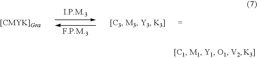
- Equation 6 may be inserted back into Equation 5 and combined to produce Equation 7.
- the virtual C 3 M 3 Y 3 K 3 printer colors may be replaced with genuine CMYOVK colors, to produce 6-color overlays, as described by Equation 7.
- the black color may have been given consideration, and every point within the printer C 1 M 1 Y 1 O 1 V 2 K 3 gamut may be realized.
- This printer gamut is illustrated in FIG. 4 , which shows the added gamut associated with the addition of black.
- the added gamut region F of the GraCol CMYK source color that may only be achieved using printer black.
- Other regions of the gamut could stay the same but are likely to use some black colorant to allow for a smooth transition from regions that may use black into regions that must use black.
- this cascaded model that exploits the virtual color methodology may be used to reassign each printer assignment throughout the printer gamut into a 6-color C 1 M 1 Y 1 O 1 V 2 K 3 assignment.
- the embodiment discussed thus far may be the most complex case, wherein the source color space (e.g. Gracol CMYK) has a larger gamut than the 4+ color printer in some areas, but the 4+ color printer gamut extends beyond the source space in other areas (e.g. as represented by region A in FIG. 2 b ).
- the entire 4+ color printer gamut is exploited.
- an embellished virtual source color space may be employed.
- an original source space e.g. Gracol CMYK
- hue angle is held constant, the saturation and lightness is scaled as necessary to encompass the entire 4+ color printer gamut.
- existing 4-color tools may be leveraged to construct a color solution to an N-color system, where N>4. This may be accomplished by executing a succession of steps that are each made to appear as conventional 4-color tasks.
- the first task may be a 4-color problem.
- Subsequent tasks may assume that printer colors are virtual, to produce solutions to system colors with more than 4 colorants.
- Each 4-color solution step brings one additional color separation into the model.
- this technique may include changing the order of the colors to be added to each 4-color model. For instance, violet V may be processed first instead of orange O.
- this technique may be used to solve a system color for a machine with more (or less) than 6 colors using the above exemplary methodology.
- every part of the realizable printer gamut may use each color as that color is brought into the model. For example, the region of the printer gamut that could be achieved by using only printer CMY could choose to make use of orange based on the first stage of the model (which only supports C 1 M 1 Y 1 O 1 ). This same region may use some printer violet colorant after the second stage of the model is complete (which only supports C 1 M 1 Y 1 O 1 V 2 ).
- Such smoothening may be performed by using a relaxation technique, where each sample point of the gamut is adjusted based on context using a weighted sampling of neighboring points. This is performed iteratively until the solution converges to a smooth stationary result, or any known smoothing method.
- the process starts at S 100 and continues to step S 105 .
- step S 105 to start the first 4-color solution model, GraCol CMY is taken from the color information of input image data.
- the GraCol CMY may then be processed with a colorant other than traditional 4-color colorants (CMYK).
- CMYK traditional 4-color colorants
- orange O is processed at step S 110 to generate printer color C 1 M 1 Y 1 O 1 .
- a collection of printer CMYO patches may be mapped, and the L*a*b* values for the patches may be measured ([CMYO] printer ⁇ L*a*b*); where ([CMYO] printer represents the CMYO color information based on the colors supported by the 4+ color printing system). Based on the L*a*b* values, the printer may be characterized so that for every combination of printer CMYO, the corresponding L*a*b* value may be determined.
- an optional smoothing may be performed on C 1 M 1 Y 1 O 1 .
- the smoothing may be performed to smoothen the mapping from source color to C 1 M 1 Y 1 O 1 usage.
- Such smoothening may be performed by using a relaxation technique, where each sample point of the gamut is adjusted based on context using a weighted sampling of neighboring points. This is performed iteratively until the solution converges to a smooth stationary result, or any known smoothing method.
- the object for smoothing the mapping is to guarantee that small changes in input color correspond to small changes in output colorant usage.
- sweeps over any interval of input color may correspond to fixed or smoothly changing usage of each output colorant, with low levels of curvature.
- step S 125 the processed C 1 M 1 Y 1 O 1 is mapped using the forward printer model to virtual colors C 2 M 2 Y 2 , which may be similar to GraCol CMY.
- a 4-color virtual printer (4CVP) deception may begin by substituting patches of printer CMY with GraCol CMY, which is then replaced with printer CMYO using the first inverse printer model.
- C G M G Y G may be equivalent to C 2 M 2 Y 2 processed at step S 125 .
- the violet V may be added to be processed with the virtual colors C 2 M 2 Y 2 .
- C 2 M 2 Y 2 may be interpreted as virtual GraCol colors, which may be replaced using a 4-color substitution using the first 4-color solution.
- C 2 M 2 Y 2 are generated from the first processed 4-color solution.
- C 2 M 2 Y 2 V 2 patches are used to characterize the printer for the second model
- the virtual C 2 M 2 Y 2 printer colors may be replaced with genuine C 1 M 1 Y 1 O 1 colors as generated at step S 125 , to assess the printer response to 5-color printer CMYOV overlays. Therefore, at step S 140 , C 1 M 1 Y 1 O 1 V 2 may be generated by replacing C 2 M 2 Y 2 with C 1 M 1 Y 1 O 1 as generated at step S 125 .
- the printer C 1 M 1 Y 1 O 1 V 2 gamut may be mapped. Every point within the printer C 1 M 1 Y 1 O 1 V 2 gamut may be realized as shown in FIG. 3 , which shows the added gamut associated with the addition of the violet V.
- FIG. 3 shows the added gamut associated with the addition of the violet V.
- the added gamut of region D as shown in FIG. 3 may be achieved by using the violet colorant, and the gamut region supported by CMYO may remain the same, but it is also permitted to exploit some violet colorant to allow for a smooth transition of colorant usage throughout the gamut.
- step S 150 the optional smoothing on the C 1 M 1 Y 1 O 1 V 2 may be performed at step S 150 , and at step S 155 , the processed C 1 M 1 Y 1 O 1 V 2 is mapped back to virtual colors C 3 M 3 Y 3 using the second forward printer model.
- the third 4-color solution model starts at step S 160 .
- a second 4-color virtual printer (4CVP) deception may begin by again taking the GraCol CMY as the colors used in the virtual printer.
- C G M G Y G may be equivalent to C 3 M 3 Y 3 processed at the second solution.
- the black color K is added to be processed with the C 3 M 3 Y 3 .
- C 3 M 3 Y 3 colorants are virtual colorants that may be interpreted as GraColCMY, which may be replaced using the results from the prior 4-color models.
- C 3 M 3 Y 3 may be generated from the previously processed 4-color solutions.
- step S 170 when C 3 M 3 Y 3 K 3 patches are used to characterize the printer for the third model, the virtual C 3 M 3 Y 3 printer colors may be replaced with genuine C 1 M 1 Y 1 O 1 V 2 colors as generated at step S 155 , to produce 6-color CMYOVK overlays.
- step S 175 the printer C 1 M 1 Y 1 O 1 V 2 K 3 may be mapped.
- step S 180 optional smoothing on the C 1 M 1 Y 1 O 1 V 2 K 3 may be performed at step S 180 , and at step S 185 , the processed C 1 M 1 Y 1 O 1 V 2 K 3 may be output to a device, such as a printing engine, for rendering the processed image.
- a device such as a printing engine
- FIG. 6 shows a block diagram of an exemplary 4+ color management device 600 according to an embodiment of the application for achieving N-color management using 4-color tools, where N>4.
- the 4+ color management device 600 includes a controller 610 , a memory 620 , a 4-color printer model calculating unit 630 , a color mapping unit 640 , an optional smoothing unit 650 , and a color replacing unit 660 .
- the controller 610 , the memory 620 , the 4-color printer model calculating unit 630 , the color mapping unit 640 , the smoothing unit 650 and the color replacing unit 660 may be connected to each other by a bus 670 .
- the 4+ color management device 600 may receive color information representing image data from an image processor 680 and transmit output information to a device, such as a printing engine 690 .
- the image processor 680 and the printing engine 690 may be connected to the 4+ color management device 600 by communication links 700 and 710 .
- the controller 610 may control data flow between elements of the 4+ color management device 600 .
- the memory 620 may serve as a buffer for information coming into or going out of the 4+ color management device 600 , may store any necessary programs and/or data for implementing the functions of the 4+ color management device 600 , and/or may store other types of data, such as color data at various stages of processing.
- Alterable portions of the memory 620 may be, in various exemplary embodiments, implemented using static or dynamic RAM. However, the memory 620 can also be implemented using a computer executable media, such as a floppy disk and disk drive, a writable or rewritable optical disk, disk drive, such as a hard disk drive, flash memory or the like.
- the generally static portions of the memory 620 may, in various exemplary embodiments, be implemented using ROM.
- the static portions can also be implemented using other non-volatile memory, such as PROM, EPROM, EEPROM, an optical ROM disk, such as a CD-ROM or DVD-ROM, and disk drive, flash memory or other alterable memory, as indicated above, or the like.
- the 4-color printer model calculating unit 630 may receive tristimulous data produced by a scanner or spectrophotometer. This data (e.g. CIE L*a*b* or spectral reflectance functions) may be generated by measuring print samples produced by the print engine, 690 . The image data may contain the color information based on the colors supported by the printing device having the printing engine 690 . In the exemplary embodiment, it is assumed that the printing engine 690 supports six colors, CMYOVK. Then, the 4-color printer model calculating unit 630 may take GraCol CMY, and orange 0 from the received image data, to generate printer color C 1 M 1 Y 1 O 1 . However, embodiments are not limited to this.
- the color mapping unit 640 may map the processed printer color C 1 M 1 Y 1 O 1 patches using the L*a*b* values for the patches ([CMYO] printer ⁇ L*a*b*); where ([CMYO] printer represents the CMYO color information based on the colors supported by the 4+ color printing system). Based on the L*a*b* values, the printer may be characterized so that for every combination of printer CMYO, the corresponding L*a*b* value may be estimated.
- the color mapping unit 640 may employ a 3-D look-up-table (LUT) to index tristimulous values (e.g. L*a*b*) to 4-D printer colorant usage (e.g. CMYO).
- LUT 3-D look-up-table
- the 3-D LUT is a sampled version of the gamut, and interpolation may be used to map every point in the gamut to the corresponding 4-color overlay required, as illustrated by the shaded areas on FIG.
- region A which is not useful because the gamut is beyond the combination of GraCol CMYK
- region B that represents the mapping of realizable destination colors for only C 1 M 1 Y 1 without the use of any orange colorant O 1
- region C which may only be achieved by using some of the gamut extension colorant, i.e., orange O 1 in FIG. 2 b.
- the smoothing unit 650 may optionally perform smoothing on C 1 M 1 Y 1 O 1 .
- the smoothing may be performed to guarantee that any smooth sweeps in tristimulous value (e.g. L*a*b*) correspond to smoothly changing 4-color overlay composition.
- Such smoothening operation may be performed by using a relaxation technique, where each sample point of the gamut is adjusted based on context using a weighted sampling of neighboring points. On the gamut boundary, an encompassing context may not be available. However, a modified approach possibly using extrapolation can be used to guarantee smoothness at the boundary without gamut loss. This smoothing operation is performed iteratively until the solution converges to a smooth stationary result, or any known method.
- the color replacement unit 660 may replace the processed C 1 M 1 Y 1 O 1 with C 2 M 2 Y 2 using the first forward printer model for C 1 M 1 Y 1 O 1 .
- the color replacement unit 660 responds to demands for C 2 M 2 Y 2 patch requirements needed by the print engine 690 to produce input data to be transmitted to construct the second color model using the 4-color printer model calculating unit 630 .
- violet V may then added to C 2 M 2 Y 2 .
- C 2 M 2 Y 2 V 2 may be generated.
- C 2 M 2 Y 2 colorants may not be raw printer colors and may be interpreted as virtual GraCol colors, which may be replaced using a 4-color substitution using the first 4-color solution.
- C 2 M 2 Y 2 may generated from the previously processed 4-color solution. Therefore, when C 2 M 2 Y 2 V 2 patches are used to characterize the printer for the second model, the virtual C 2 M 2 Y 2 printer colors are replaced with genuine C 1 M 1 Y 1 O 1 colors by the color replacement unit 660 , to produce 5-color CMYOV overlays. Therefore, the 4-color model calculating unit 630 can use C 1 M 1 Y 1 O 1 V 2 patches by replacing C 2 M 2 Y 2 with C 1 M 1 Y 1 O 1 .
- the color mapping unit 640 may then realize every point within the printer C 1 M 1 Y 1 O 1 V 2 gamut as shown in FIG. 3 using interpolation.
- the points used to perform this interpolation may have been adjusted by smoothing unit 650 .
- Areas supported by the printer CMYO may remain the same, but the added gamut may contain region D of the GraCol CMYK source color, which may only be achieved using the violet colorant.
- the color mapping unit 640 may provide region E shown in FIG. 3 , which may lie beyond GraCol CMYK and may not be utilized.
- the color replacement unit 660 then replaces the processed C 1 M 1 Y 1 O 1 V 2 with C 3 M 3 Y 3 using the forward printer model.
- the 4-color printer model calculating unit 630 may use overlay patches of C 3 M 3 Y 3 K 3 that are mapped to C 1 M I Y 1 O 1 V 2 K 3 by the color replacement unit 660 . The tristimulous values corresponding to these patches are transmitted to the 4-color model calculating unit 630 to produce the final color model.
- C 3 M 3 Y 3 may be generated from the previously processed 4-color solution. Therefore, when C 3 M 3 Y 3 K 3 patches are used to characterize the printer for the second model, the 4-color printer model calculating unit 630 may replace the C 3 M 3 Y 3 printer colors with genuine C 1 M 1 Y 1 O 1 V 2 colors to produce 6-color CMYOVK overlays.
- the color mapping unit 640 may then realize every point within the printer C 1 M 1 Y 1 O 1 V 2 K 3 gamut as shown in FIG. 4 .
- the smoothing unit 650 may smooth the relationship between sweeps of input color and the corresponding overlay sweeps in printer colorants C 1 M 1 Y 1 O 1 V 2 K 3 .
- the image processor 680 may be any known or later-developed device that is capable of collecting and transmitting image information to the 4+ color management device 600 , such as an image scanner or spectrophotometer.
- the printing engine 690 may be any known or later-developed device that marks the processed image data, such as a laser printer, an inkjet printer, and a xerographic machine.
- the bus 670 may be any known or later-developed device or system for connecting the controller 610 , the memory 620 , the 4-color printer model calculating unit 630 , the color mapping unit 640 , the smoothing unit 650 , and the color replacing unit 660 .
- the communication links 700 and 710 may be any known or later-developed devices or systems for connecting the image processor 680 and the printing engine 690 , respectively, to the 4+ color management device 600 .
- These communication links 700 and 710 may be a direct cable or bus connection, a connection over a wide area network or local area network, a connection over an intranet, a connection over the Internet, or a connection over any other distributed processing network. Further, it should be appreciated that the communication links 700 and 710 can be wireless connections over a network.
- the network can be a local area network, a wide area network, an intranet, the Internet, or any other known or later-developed other distributed processing and storage network.
- the 4+ color management device 600 can be implemented using a programmed general-purpose computer. However, the 4+ color management device 600 can also be implemented using a special purpose computer, a programmed microprocessor or microcontroller and peripheral integrated circuit elements, and ASIC or other integrated circuit, a digital signal processor, a hardware electronic or logic circuit, such as a discrete element circuit, a programmable logic device, such as PLD, PLA, FPGA or PAL, or the like. In general, any device, capable of implementing a finite state machine that is in turn capable of implementing the flowcharts shown in FIG. 5 can be used to implement the 4+ color management device 600 .
- Each of the units and elements of the various exemplary embodiments of the 4+ color management device 600 outlined above can be implemented as portions of a suitable programmed general purpose computer.
- each of the units and elements of the various exemplary embodiments of the 4+ color management device 600 outlined above can be implemented as physically distinct hardware circuits within an ASIC, or using FPGA, a PDL, a PLA or a PAL, or using discrete logic elements or discrete circuit elements.
- the particular form each of the circuits and elements of the various exemplary embodiments of the 4+ color management device 600 outlined above will take is a design choice and will be obvious and predictable to those skilled in the art.
- the various exemplary embodiments of the 4+ color management device 600 outlined above and/or various units of the various units and elements discussed above can be implemented as software routines, managers or objects executing on a programmed general purpose computer, a special purpose computer, a microprocessor or the like.
- the various exemplary embodiments of the 4+ color management device 600 and/or each or the various units and elements discussed above can each be implemented as one or more routines embedded in the communication network, as a resource residing on a server, or the like.
- the various exemplary embodiments of the 4+ color management device 600 and the various units and elements discussed above can also be implemented by physically incorporating the 4+ color management device 600 into software run by a processor and/or a hardware system, such as the hardware and software system of a web server or a client device.
Landscapes
- Engineering & Computer Science (AREA)
- Multimedia (AREA)
- Signal Processing (AREA)
- Textile Engineering (AREA)
- Color Image Communication Systems (AREA)
- Facsimile Image Signal Circuits (AREA)
Abstract
Description
where the GraCol CMYK source color information is referred to as [CMYK]Gra. In this example, the first four system output colors accommodated may be CMYO as discussed above, and the processed first four system output colors are referred to as [C1M1Y1O1]. This is the first 4-color model to be generated using a conventional 4-color procedure and 4-color tool, as indicated by the subscripts “1” in


Claims (20)
Priority Applications (1)
| Application Number | Priority Date | Filing Date | Title |
|---|---|---|---|
| US12/463,469 US8089659B2 (en) | 2009-05-11 | 2009-05-11 | 4+ color management for gamut extension using a virtual CMYK methodology |
Applications Claiming Priority (1)
| Application Number | Priority Date | Filing Date | Title |
|---|---|---|---|
| US12/463,469 US8089659B2 (en) | 2009-05-11 | 2009-05-11 | 4+ color management for gamut extension using a virtual CMYK methodology |
Publications (2)
| Publication Number | Publication Date |
|---|---|
| US20100284029A1 US20100284029A1 (en) | 2010-11-11 |
| US8089659B2 true US8089659B2 (en) | 2012-01-03 |
Family
ID=43062188
Family Applications (1)
| Application Number | Title | Priority Date | Filing Date |
|---|---|---|---|
| US12/463,469 Expired - Fee Related US8089659B2 (en) | 2009-05-11 | 2009-05-11 | 4+ color management for gamut extension using a virtual CMYK methodology |
Country Status (1)
| Country | Link |
|---|---|
| US (1) | US8089659B2 (en) |
Citations (8)
| Publication number | Priority date | Publication date | Assignee | Title |
|---|---|---|---|---|
| US20030098896A1 (en) * | 2001-11-01 | 2003-05-29 | Berns Roy S. | Spectral color reproduction with six color output |
| US20040114166A1 (en) * | 2002-12-12 | 2004-06-17 | Fuji Xerox Co., Ltd. | Color image processing method, color image processing apparatus, color image processing program, and record medium |
| US20050128491A1 (en) * | 2003-12-15 | 2005-06-16 | Fuji Xerox Co., Ltd. | Color image processing method, color image processor and storage medium |
| US20060250624A1 (en) * | 2005-05-04 | 2006-11-09 | Eastman Kodak Company | Colorant control values for color printing devices |
| US20060285742A1 (en) * | 2003-11-03 | 2006-12-21 | Yoshifumi Arai | Production of color conversion profile for printing |
| US20100085586A1 (en) * | 2008-10-06 | 2010-04-08 | Canon Kabushiki Kaisha | Target for color characterization of color printer |
| US20110122426A1 (en) * | 2009-11-24 | 2011-05-26 | Canon Kabushiki Kaisha | Spectral gamut mapping by constrained subdivision of gamut |
| US20110149307A1 (en) * | 2009-12-18 | 2011-06-23 | Canon Kabushiki Kaisha | Selection of samples for spanning a spectral gamut |
-
2009
- 2009-05-11 US US12/463,469 patent/US8089659B2/en not_active Expired - Fee Related
Patent Citations (9)
| Publication number | Priority date | Publication date | Assignee | Title |
|---|---|---|---|---|
| US20030098896A1 (en) * | 2001-11-01 | 2003-05-29 | Berns Roy S. | Spectral color reproduction with six color output |
| US20040114166A1 (en) * | 2002-12-12 | 2004-06-17 | Fuji Xerox Co., Ltd. | Color image processing method, color image processing apparatus, color image processing program, and record medium |
| US20060285742A1 (en) * | 2003-11-03 | 2006-12-21 | Yoshifumi Arai | Production of color conversion profile for printing |
| US20050128491A1 (en) * | 2003-12-15 | 2005-06-16 | Fuji Xerox Co., Ltd. | Color image processing method, color image processor and storage medium |
| US20060250624A1 (en) * | 2005-05-04 | 2006-11-09 | Eastman Kodak Company | Colorant control values for color printing devices |
| US7535596B2 (en) * | 2005-05-04 | 2009-05-19 | Eastman Kodak Company | Colorant control values for color printing devices |
| US20100085586A1 (en) * | 2008-10-06 | 2010-04-08 | Canon Kabushiki Kaisha | Target for color characterization of color printer |
| US20110122426A1 (en) * | 2009-11-24 | 2011-05-26 | Canon Kabushiki Kaisha | Spectral gamut mapping by constrained subdivision of gamut |
| US20110149307A1 (en) * | 2009-12-18 | 2011-06-23 | Canon Kabushiki Kaisha | Selection of samples for spanning a spectral gamut |
Also Published As
| Publication number | Publication date |
|---|---|
| US20100284029A1 (en) | 2010-11-11 |
Similar Documents
| Publication | Publication Date | Title |
|---|---|---|
| KR100902700B1 (en) | Color processing method and color processing apparatus | |
| JP5538743B2 (en) | Image processing apparatus, image processing method, and program | |
| EP1156668B1 (en) | Black generation for color management system | |
| US8638474B2 (en) | Image processing apparatus and color conversion table generating method | |
| JP2008028679A (en) | Color conversion table, and method and device for generating the same | |
| US7782487B2 (en) | Image processing apparatus, image forming apparatus, image processing method, computer data signal, and recording medium | |
| US8270029B2 (en) | Methods, apparatus and systems for using black-only on the neutral axis in color management profiles | |
| US8040568B2 (en) | 4+ color management using a virtual CMYK color paradigm | |
| US8089659B2 (en) | 4+ color management for gamut extension using a virtual CMYK methodology | |
| CN105704347A (en) | Image processing apparatus and image processing method | |
| US8913311B1 (en) | Natural ink limit encoding for digital color managed workflow systems | |
| JP2019071537A (en) | Image processing device, control method of the same, and program | |
| US7679782B2 (en) | System and method for extracting grayscale data in accordance with a prescribed tolerance function | |
| JP5074901B2 (en) | Color processing method and image forming apparatus | |
| JP2009284488A (en) | Image processing system and method | |
| Reinhard et al. | Perceptually optimizing color look-up tables | |
| JP4613940B2 (en) | Color signal conversion apparatus, image forming apparatus, and program | |
| JP5012336B2 (en) | Device link profile creation apparatus, method and program thereof, and color conversion processing apparatus | |
| JP2008005501A (en) | System and method for color space conversion | |
| JP2019050569A (en) | Mechanism to perform color forcing parameter conversion | |
| JP5049768B2 (en) | Color separation table creation method and image forming apparatus | |
| US8351099B2 (en) | Hue specific monochromatic printing mechanism | |
| JP2008172789A (en) | Image forming apparatus and image forming method | |
| JP2009273122A (en) | Image processing system and method | |
| JP2009147755A (en) | Color processing apparatus, and method thereof |
Legal Events
| Date | Code | Title | Description |
|---|---|---|---|
| AS | Assignment |
Owner name: XEROX CORPORATION, CONNECTICUT Free format text: ASSIGNMENT OF ASSIGNORS INTEREST;ASSIGNORS:LIEBERMAN, DAVID J.;SCHWEID, STUART A.;REEL/FRAME:022670/0584 Effective date: 20090506 |
|
| FEPP | Fee payment procedure |
Free format text: PAYOR NUMBER ASSIGNED (ORIGINAL EVENT CODE: ASPN); ENTITY STATUS OF PATENT OWNER: LARGE ENTITY |
|
| ZAAA | Notice of allowance and fees due |
Free format text: ORIGINAL CODE: NOA |
|
| ZAAB | Notice of allowance mailed |
Free format text: ORIGINAL CODE: MN/=. |
|
| STCF | Information on status: patent grant |
Free format text: PATENTED CASE |
|
| FPAY | Fee payment |
Year of fee payment: 4 |
|
| MAFP | Maintenance fee payment |
Free format text: PAYMENT OF MAINTENANCE FEE, 8TH YEAR, LARGE ENTITY (ORIGINAL EVENT CODE: M1552); ENTITY STATUS OF PATENT OWNER: LARGE ENTITY Year of fee payment: 8 |
|
| AS | Assignment |
Owner name: CITIBANK, N.A., AS AGENT, DELAWARE Free format text: SECURITY INTEREST;ASSIGNOR:XEROX CORPORATION;REEL/FRAME:062740/0214 Effective date: 20221107 |
|
| AS | Assignment |
Owner name: XEROX CORPORATION, CONNECTICUT Free format text: RELEASE OF SECURITY INTEREST IN PATENTS AT R/F 062740/0214;ASSIGNOR:CITIBANK, N.A., AS AGENT;REEL/FRAME:063694/0122 Effective date: 20230517 |
|
| AS | Assignment |
Owner name: CITIBANK, N.A., AS COLLATERAL AGENT, NEW YORK Free format text: SECURITY INTEREST;ASSIGNOR:XEROX CORPORATION;REEL/FRAME:064760/0389 Effective date: 20230621 |
|
| FEPP | Fee payment procedure |
Free format text: MAINTENANCE FEE REMINDER MAILED (ORIGINAL EVENT CODE: REM.); ENTITY STATUS OF PATENT OWNER: LARGE ENTITY |
|
| AS | Assignment |
Owner name: JEFFERIES FINANCE LLC, AS COLLATERAL AGENT, NEW YORK Free format text: SECURITY INTEREST;ASSIGNOR:XEROX CORPORATION;REEL/FRAME:065628/0019 Effective date: 20231117 |
|
| LAPS | Lapse for failure to pay maintenance fees |
Free format text: PATENT EXPIRED FOR FAILURE TO PAY MAINTENANCE FEES (ORIGINAL EVENT CODE: EXP.); ENTITY STATUS OF PATENT OWNER: LARGE ENTITY |
|
| STCH | Information on status: patent discontinuation |
Free format text: PATENT EXPIRED DUE TO NONPAYMENT OF MAINTENANCE FEES UNDER 37 CFR 1.362 |
|
| AS | Assignment |
Owner name: XEROX CORPORATION, CONNECTICUT Free format text: TERMINATION AND RELEASE OF SECURITY INTEREST IN PATENTS RECORDED AT RF 064760/0389;ASSIGNOR:CITIBANK, N.A., AS COLLATERAL AGENT;REEL/FRAME:068261/0001 Effective date: 20240206 Owner name: CITIBANK, N.A., AS COLLATERAL AGENT, NEW YORK Free format text: SECURITY INTEREST;ASSIGNOR:XEROX CORPORATION;REEL/FRAME:066741/0001 Effective date: 20240206 |
|
| FP | Lapsed due to failure to pay maintenance fee |
Effective date: 20240103 |