US8089433B2 - Contrast ratio enhancement system using black detector - Google Patents
Contrast ratio enhancement system using black detector Download PDFInfo
- Publication number
- US8089433B2 US8089433B2 US12/160,057 US16005706A US8089433B2 US 8089433 B2 US8089433 B2 US 8089433B2 US 16005706 A US16005706 A US 16005706A US 8089433 B2 US8089433 B2 US 8089433B2
- Authority
- US
- United States
- Prior art keywords
- blackness
- pixels
- frame
- video data
- level
- Prior art date
- Legal status (The legal status is an assumption and is not a legal conclusion. Google has not performed a legal analysis and makes no representation as to the accuracy of the status listed.)
- Active, expires
Links
Images


Classifications
-
- G—PHYSICS
- G09—EDUCATION; CRYPTOGRAPHY; DISPLAY; ADVERTISING; SEALS
- G09G—ARRANGEMENTS OR CIRCUITS FOR CONTROL OF INDICATING DEVICES USING STATIC MEANS TO PRESENT VARIABLE INFORMATION
- G09G3/00—Control arrangements or circuits, of interest only in connection with visual indicators other than cathode-ray tubes
- G09G3/20—Control arrangements or circuits, of interest only in connection with visual indicators other than cathode-ray tubes for presentation of an assembly of a number of characters, e.g. a page, by composing the assembly by combination of individual elements arranged in a matrix no fixed position being assigned to or needed to be assigned to the individual characters or partial characters
- G09G3/34—Control arrangements or circuits, of interest only in connection with visual indicators other than cathode-ray tubes for presentation of an assembly of a number of characters, e.g. a page, by composing the assembly by combination of individual elements arranged in a matrix no fixed position being assigned to or needed to be assigned to the individual characters or partial characters by control of light from an independent source
- G09G3/3406—Control of illumination source
-
- G—PHYSICS
- G09—EDUCATION; CRYPTOGRAPHY; DISPLAY; ADVERTISING; SEALS
- G09G—ARRANGEMENTS OR CIRCUITS FOR CONTROL OF INDICATING DEVICES USING STATIC MEANS TO PRESENT VARIABLE INFORMATION
- G09G2320/00—Control of display operating conditions
- G09G2320/06—Adjustment of display parameters
- G09G2320/0626—Adjustment of display parameters for control of overall brightness
- G09G2320/064—Adjustment of display parameters for control of overall brightness by time modulation of the brightness of the illumination source
-
- G—PHYSICS
- G09—EDUCATION; CRYPTOGRAPHY; DISPLAY; ADVERTISING; SEALS
- G09G—ARRANGEMENTS OR CIRCUITS FOR CONTROL OF INDICATING DEVICES USING STATIC MEANS TO PRESENT VARIABLE INFORMATION
- G09G2320/00—Control of display operating conditions
- G09G2320/06—Adjustment of display parameters
- G09G2320/0626—Adjustment of display parameters for control of overall brightness
- G09G2320/0646—Modulation of illumination source brightness and image signal correlated to each other
-
- G—PHYSICS
- G09—EDUCATION; CRYPTOGRAPHY; DISPLAY; ADVERTISING; SEALS
- G09G—ARRANGEMENTS OR CIRCUITS FOR CONTROL OF INDICATING DEVICES USING STATIC MEANS TO PRESENT VARIABLE INFORMATION
- G09G2360/00—Aspects of the architecture of display systems
- G09G2360/16—Calculation or use of calculated indices related to luminance levels in display data
Definitions
- the present invention relates generally to display systems. More specifically, the present invention relates to a system and method for enhancing contrast ratio in certain display systems.
- LCD Liquid Crystal Displays
- CRT Cathode Ray Tubes
- contrast ratio As an example, the contrast ratio of high-end LCD panels is generally about 500:1, while for a CRT, 10,000:1 is a common ratio.
- the contrast ratio may be defined as the ratio of the amount of light of the brightest white to the darkest black of a video frame.
- pixels of LCD panels transmit enough light, even when in their darkest state, such that a black colored pixel displayed on the LCD panel actually appears to be displayed as a dark gray pixel. Consequently, this significantly lowers the contrast ratio of the LCD panel, which may be more objectionable in low light viewing conditions.
- the disclosed embodiments relate to a system and method that enhance a contrast ratio of a display device, comprising determining a quantity of pixels in a frame of video data having a predetermined level of blackness, comparing the quantity of pixels to a reference value, and modulating an illumination signal based on a quantity of pixels exceeding the reference value.
- the disclosed system and method may further apply to digital light displays (DLPs) and to liquid crystal on silicon (LCOS) display systems.
- DLPs digital light displays
- LCOS liquid crystal on silicon
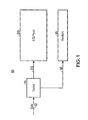
- FIG. 1 is a block diagram of an LCD panel in accordance with an exemplary embodiment of the present invention
- FIG. 2 is a block diagram of a contrast ratio enhancing system in accordance with an exemplary embodiment of the present invention
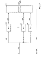
- FIG. 3 is block diagram of black horizon finder in accordance with an exemplary embodiment of the present invention.
- FIG. 4 is a block diagram of a maximum white generator in accordance with an exemplary embodiment of the present invention.
- FIG. 5 is flow chart depicting a method for obtaining a required backlight illumination based on black areas of a video frame in accordance with an exemplary embodiment of the present invention.
- FIG. 1 a configuration of an exemplary LCD panel system 10 in accordance with an embodiment of the present invention is shown.
- the figure depicts an LCD panel 20 and a backlight 18 controlled by a control system 14 .
- the control system 14 receives data 12 , which may include video backlight illumination and liquid crystal pixel data values.
- the control system 14 may use the data 12 to simultaneously adjust the backlight and the pixel values to enhance the contrast ratio of the LCD panel 20 .
- data 22 outputted by the control system 14 goes into the LCD panel 20 for adjusting the pixel values.
- data 16 outputted by the control system 14 is transmitted into the backlight 18 for adjusting the backlight illumination of the video.
- a contrast ratio enhancement control system 40 in accordance with an exemplary embodiment of the present invention is shown.
- the description set forth of the control system 40 pertains to components controlling the video backlight illumination and the pixel values of the LCD panel 20 .
- a white horizon finder 44 and a black horizon finder 45 receive respective luminance component data 42 .
- the white horizon finder 44 and the black horizon finder 45 respectively determine statistical information relating to the brightness levels and blackness levels, as well as their distribution throughout a video frame.
- Information obtained by the white horizon finder 44 and the black horizon finder 45 is delivered to a maximum white generator 46 .
- the maximum white generator 46 controls the backlight illumination and the liquid crystal pixel values.
- backlight illumination and pixel values are controlled at the same time.
- the two are adjusted in a complementary fashion to enhance the contrast ratio of the LCD panel 20 .
- the maximum white generator 46 controls the backlight illumination by determining the brightness of the brightest area of the video frame. This information is then utilized to determine the amount of backlight needed to illuminate the LCD panel 20 , for example, as applied by cold-cathode-fluorescent (CCF) lamps. To improve the contrast ratio, a reduced backlight illumination is desired. However, reducing the backlight illumination too much may cause an undesired “white reduction” of the video frame. In order to avoid this, brightness information obtained by the maximum white generator 46 is further utilized to modify the pixel values of the LCD panel to compensate for possible insufficient backlight illumination.
- CCF cold-cathode-fluorescent
- the maximum white generator 46 produces data 50 , which may be used to simultaneously adjust the backlight illumination data and red, green, and blue (RGB) input values of the LCD panel 20 .
- the data 50 may be delivered to backlight control circuitry, which provides control data 58 .
- backlight control circuitry may include: a rise/fall delay circuit 52 , which compensates for time misalignments between the backlight illumination and the raster scanning of the pixels. This may prevent viewer perceived white flashes appearing on a screen, which are generally undesired.
- a backlight linearizer 54 which compensates for nonlinearity in the light characteristic of the backlight
- PWM backlight pulse width modulator
- maximum white data 50 is provided by the maximum white generator 46 for modifying the pixel values of the LCD panel 20 in a non-linear gamma-corrected domain. Accordingly, the data 50 is delivered to a contrast look-up table (CLUT) 60 , which stores adjustment values that are formatted as an RGB offset 62 and an RGB gain-value 64 . The RGB offset value 62 and the RGB gain-value 64 are delivered to an RGB contrast circuit 66 . Accordingly, input RGB pixel values 68 - 72 are combined with the RGB offset 62 and the RGB gain-value 64 to yield gamma-corrected RGB pixel values 74 - 78 .
- CLUT contrast look-up table
- the black horizon finder 45 acquires and quantifies statistical data of blackness or black and near-black levels in each a video frame.
- the maximum white generator 46 may acquire the statistical information to advantageously modulate the backlight illumination and enhance the contrast ratio of a display system 20 . For example, in a video frame containing insignificant quantities of near-black levels, it may be more efficient and desirable not modulate the backlight illumination at all.
- the black horizon finder 45 analyzes the input data 42 . Particularly, the black horizon finder 45 may use the data 42 to obtain the cumulative quantity of black pixels in every frame which fall below a certain blackness level. This cumulative quantity of pixels is then compared to a configurable threshold. Upon determining that the cumulative number of pixels exceeds the threshold, the backlight illumination is permitted to be modulated.
- FIG. 3 a block diagram in accordance with an exemplary embodiment of the present technique is illustrated.
- the block diagram depicts a circuit 90 adapted to obtain statistical information of blackness levels in a video frame.
- backlight illumination data 42 is delivered to an array of bins 96 - 100 .
- three bins are shown in FIG. 3 , other numbers of bins may be employed based on system design criteria.
- An exemplary embodiment of the present invention employs nine bins.
- the purpose of each of the bins 96 - 100 is to respectively count the number of pixels in each video frame that fall below a certain blackness level.
- the bin 96 may include, for example, all pixels having values of shades of gray that are below 4.
- bin 100 may include all pixels having values of shades of gray that are below 36. In this manner, a histogram of nine bins is obtained, where each bin total enumerates the number of pixels falling below a certain blackness level.
- the bins 96 - 100 produce respective pixel count data 102 - 105 , delivered to a programmable horizon finder 106 .
- the purpose of the programmable horizon finder 106 is to compare each of the data inputs 102 - 105 to a configurable black threshold 94 . Such a comparison may yield the bin number 96 - 100 having the quantity of black and near black pixels exceeding and/or matching the black threshold 94 .
- knowing the threshold-matching bin number and its corresponding blackness level may determine the effective blackness area contained in the video frame. This information may further be used by the maximum white generator 46 to determine the degree of modulation needed for the backlight.
- the programmable horizon finder 106 produces a data output 108 for each video frame quantifying the bin number closest to the threshold 94 .
- the resolution of the data output is six bits. Accordingly, an advantage of the system 90 is its ability to quantify black and near black levels of a video frame via sixty four states of resolution, while employing a significantly reduced number of hardware-implemented bins to classify the sixty four states of resolution. It is believed that the use of nine bins with six bit resolution provides an effective tradeoff between resolution and system complexity.
- FIG. 4 is a block diagram of a circuit 120 in accordance with an exemplary embodiment of the present invention.
- the circuit 120 depicts components comprising the maximum white generator 46 for processing video illumination data. Accordingly, data 122 delivered from the white horizon finder 44 , and data 108 produced by the programmable horizon finder 106 of the black horizon finder 45 are delivered to respective gain components 126 and 127 . Thereafter, these are respectively processed by adder 128 and subtractor 129 . The adder 128 and the subtractor 129 are further provided with offsets 123 and 125 respectively. Resultant data 130 and 132 are delivered into a combining circuit 134 . In an exemplary embodiment, the combining circuit 134 may be configured to identify the maximum of the values 130 and 132 .
- the combining circuit 134 may be configured to identify the minimum of the values 130 and 132 .
- FIG. 5 depicts a flow chart outlining a method in accordance with the present technique.
- the flow chart generally referred to by reference numeral 150 depicts processing steps in modulating backlight illumination using statistical information of blackness or black and near-black levels in a video frame.
- the method begins at block 152 where the data 42 is inputted into the black horizon finder 45 .
- the data 42 is used to determine a quantity of pixels in each video frame having a predetermined level of blackness or near-black levels.
- this quantity is compared to a reference value. According to the number of pixels exceeding the reference value, an illumination signal is modulated at block 158 .
- the method ends at block 160 .
Abstract
Description
max white=MAXIMUM(128+2(white horizon), 255−2(black horizon))
The foregoing equation makes use of the
Claims (20)
Applications Claiming Priority (1)
| Application Number | Priority Date | Filing Date | Title |
|---|---|---|---|
| PCT/US2006/000901 WO2007081331A1 (en) | 2006-01-11 | 2006-01-11 | Contrast ratio enhancement display system using black detector |
Publications (2)
| Publication Number | Publication Date |
|---|---|
| US20080303759A1 US20080303759A1 (en) | 2008-12-11 |
| US8089433B2 true US8089433B2 (en) | 2012-01-03 |
Family
ID=36917271
Family Applications (1)
| Application Number | Title | Priority Date | Filing Date |
|---|---|---|---|
| US12/160,057 Active 2028-02-21 US8089433B2 (en) | 2006-01-11 | 2006-01-11 | Contrast ratio enhancement system using black detector |
Country Status (4)
| Country | Link |
|---|---|
| US (1) | US8089433B2 (en) |
| EP (1) | EP1974339A1 (en) |
| CN (1) | CN101322177B (en) |
| WO (1) | WO2007081331A1 (en) |
Citations (21)
| Publication number | Priority date | Publication date | Assignee | Title |
|---|---|---|---|---|
| US5124818A (en) * | 1989-06-07 | 1992-06-23 | In Focus Systems, Inc. | LCD system having improved contrast ratio |
| US5442467A (en) | 1994-03-21 | 1995-08-15 | Xerox Corporation | Enhanced off-axis viewing performance and luminous efficiency of a liquid crystal display employing fiberoptic faceplate elements |
| JPH1173162A (en) | 1997-08-28 | 1999-03-16 | Matsushita Electric Ind Co Ltd | Simultaneous adjusting circuit for brightness and contrast of liquid crystal display monitor |
| GB2337629A (en) | 1998-05-22 | 1999-11-24 | Sharp Kk | Liquid crystal display device |
| JP2000314878A (en) | 1999-04-30 | 2000-11-14 | Fuji Photo Film Co Ltd | Monochromatic liquid crystal display |
| JP2001154638A (en) | 1999-11-24 | 2001-06-08 | Casio Comput Co Ltd | Liquid crystal display device and storage medium |
| US6681053B1 (en) | 1999-08-05 | 2004-01-20 | Matsushita Electric Industrial Co., Ltd. | Method and apparatus for improving the definition of black and white text and graphics on a color matrix digital display device |
| TW594275B (en) | 2003-10-22 | 2004-06-21 | Optimax Tech Corp | A method of enhancing contrast ratio |
| US6791607B1 (en) | 1998-07-15 | 2004-09-14 | Texas Instruments Incorporated | Optical black and offset correction in CCD signal processing |
| US20050031201A1 (en) | 2003-06-27 | 2005-02-10 | Stmicroelectronics Asia Pacific Pte Ltd. | Method and system for contrast enhancement of digital video |
| US20050062913A1 (en) | 2002-07-26 | 2005-03-24 | Jung-Min Choi | Liquid crystal display device |
| EP1522988A2 (en) | 2003-10-09 | 2005-04-13 | Pioneer Corporation | Backlight device and display apparatus |
| US6894666B2 (en) | 2001-12-12 | 2005-05-17 | Samsung Sdi Co., Ltd. | Contrast correcting circuit |
| US20050104841A1 (en) | 2003-11-17 | 2005-05-19 | Lg Philips Lcd Co., Ltd. | Method and apparatus for driving liquid crystal display |
| US20050104842A1 (en) * | 2003-11-17 | 2005-05-19 | Lg Philips Lcd Co., Ltd. | Method and apparatus for driving liquid crystal display |
| US20050125179A1 (en) | 2003-12-05 | 2005-06-09 | Genesis Microchip Inc. | LCD overdrive auto-calibration apparatus and method |
| US20050156868A1 (en) * | 2003-12-24 | 2005-07-21 | Samsung Electronics Co., Ltd. | Display and control method thereof |
| WO2005119639A1 (en) | 2004-06-01 | 2005-12-15 | Koninklijke Philips Electronics N.V. | Display device comprising a light source |
| US7253860B2 (en) | 2003-05-08 | 2007-08-07 | Au Optronics Corporation | OCB liquid crystal display with specific refractive indices and inequality relations |
| US20080136768A1 (en) * | 2006-12-11 | 2008-06-12 | Inventec Corporation | Display apparatus and method for controlling contrast thereof |
| US20080259091A1 (en) * | 2005-11-14 | 2008-10-23 | Tte Technology, Inc. | System and Method for Enhancing the Contrast Ratio of an Image |
Family Cites Families (1)
| Publication number | Priority date | Publication date | Assignee | Title |
|---|---|---|---|---|
| US6594666B1 (en) * | 2000-09-25 | 2003-07-15 | Oracle International Corp. | Location aware application development framework |
-
2006
- 2006-01-11 CN CN2006800454741A patent/CN101322177B/en active Active
- 2006-01-11 US US12/160,057 patent/US8089433B2/en active Active
- 2006-01-11 WO PCT/US2006/000901 patent/WO2007081331A1/en active Application Filing
- 2006-01-11 EP EP06718024A patent/EP1974339A1/en not_active Withdrawn
Patent Citations (21)
| Publication number | Priority date | Publication date | Assignee | Title |
|---|---|---|---|---|
| US5124818A (en) * | 1989-06-07 | 1992-06-23 | In Focus Systems, Inc. | LCD system having improved contrast ratio |
| US5442467A (en) | 1994-03-21 | 1995-08-15 | Xerox Corporation | Enhanced off-axis viewing performance and luminous efficiency of a liquid crystal display employing fiberoptic faceplate elements |
| JPH1173162A (en) | 1997-08-28 | 1999-03-16 | Matsushita Electric Ind Co Ltd | Simultaneous adjusting circuit for brightness and contrast of liquid crystal display monitor |
| GB2337629A (en) | 1998-05-22 | 1999-11-24 | Sharp Kk | Liquid crystal display device |
| US6791607B1 (en) | 1998-07-15 | 2004-09-14 | Texas Instruments Incorporated | Optical black and offset correction in CCD signal processing |
| JP2000314878A (en) | 1999-04-30 | 2000-11-14 | Fuji Photo Film Co Ltd | Monochromatic liquid crystal display |
| US6681053B1 (en) | 1999-08-05 | 2004-01-20 | Matsushita Electric Industrial Co., Ltd. | Method and apparatus for improving the definition of black and white text and graphics on a color matrix digital display device |
| JP2001154638A (en) | 1999-11-24 | 2001-06-08 | Casio Comput Co Ltd | Liquid crystal display device and storage medium |
| US6894666B2 (en) | 2001-12-12 | 2005-05-17 | Samsung Sdi Co., Ltd. | Contrast correcting circuit |
| US20050062913A1 (en) | 2002-07-26 | 2005-03-24 | Jung-Min Choi | Liquid crystal display device |
| US7253860B2 (en) | 2003-05-08 | 2007-08-07 | Au Optronics Corporation | OCB liquid crystal display with specific refractive indices and inequality relations |
| US20050031201A1 (en) | 2003-06-27 | 2005-02-10 | Stmicroelectronics Asia Pacific Pte Ltd. | Method and system for contrast enhancement of digital video |
| EP1522988A2 (en) | 2003-10-09 | 2005-04-13 | Pioneer Corporation | Backlight device and display apparatus |
| TW594275B (en) | 2003-10-22 | 2004-06-21 | Optimax Tech Corp | A method of enhancing contrast ratio |
| US20050104841A1 (en) | 2003-11-17 | 2005-05-19 | Lg Philips Lcd Co., Ltd. | Method and apparatus for driving liquid crystal display |
| US20050104842A1 (en) * | 2003-11-17 | 2005-05-19 | Lg Philips Lcd Co., Ltd. | Method and apparatus for driving liquid crystal display |
| US20050125179A1 (en) | 2003-12-05 | 2005-06-09 | Genesis Microchip Inc. | LCD overdrive auto-calibration apparatus and method |
| US20050156868A1 (en) * | 2003-12-24 | 2005-07-21 | Samsung Electronics Co., Ltd. | Display and control method thereof |
| WO2005119639A1 (en) | 2004-06-01 | 2005-12-15 | Koninklijke Philips Electronics N.V. | Display device comprising a light source |
| US20080259091A1 (en) * | 2005-11-14 | 2008-10-23 | Tte Technology, Inc. | System and Method for Enhancing the Contrast Ratio of an Image |
| US20080136768A1 (en) * | 2006-12-11 | 2008-06-12 | Inventec Corporation | Display apparatus and method for controlling contrast thereof |
Non-Patent Citations (5)
| Title |
|---|
| Konno, A., et al, 40.2: RGB Color control System for LED Backlights in IPS-LCD TVs, SID 2005 Digest, pp. 1380-1383. |
| Matsumoto, S., et al, A Single-cell high-quality black and white ST liquid-crystal display, Electronic Devices, IEEE Transactions, vol. 36, Issue 9, Sep. 1989, pp. 19-5-1909 (abstract only available). |
| Matz, S. C., et al., A nonlinear technique for image contrast enhancement and sharpening, 1999, Proceedings of the 1999 IEEE International Symposium on Circuits and Systems, vol. 4, Jul. 1999, pp. 175-178 (abstract only available). |
| PCT International Search Report and the Written Opinion of the International Searching Authority, mailed Sep. 14, 2006. |
| Raman, N., et al., Dynamic contrast enhancement of liquid crystal displays with backlight modulation, Consumer Electronics, 2005, ICCE, 2005 Digest of Technical Papers, International Conference, Jan. 8-12, 2005, pp. 197-198 (abstract only available). |
Also Published As
| Publication number | Publication date |
|---|---|
| CN101322177A (en) | 2008-12-10 |
| EP1974339A1 (en) | 2008-10-01 |
| US20080303759A1 (en) | 2008-12-11 |
| WO2007081331A1 (en) | 2007-07-19 |
| CN101322177B (en) | 2010-11-17 |
Similar Documents
| Publication | Publication Date | Title |
|---|---|---|
| US20090015602A1 (en) | Contrast Ratio Enhancement System Using Asymmetrically Delayed Illumination Control | |
| US9654701B2 (en) | Global display management based light modulation | |
| US7170477B2 (en) | Image reproducing method, image display apparatus and picture signal compensation device | |
| US8059082B2 (en) | Display device comprising an ajustable light source | |
| US8593391B2 (en) | Liquid crystal display device control circuit and liquid crystal display system, which adjust brightness of display image by using height distribution of gradations of input image | |
| US7508457B2 (en) | Video signal processor circuit and television receiver | |
| US8654058B2 (en) | Apparatus and method for enhancing image contrast | |
| US20120162532A1 (en) | Liquid crystal display apparatus and television receiver | |
| US20080259091A1 (en) | System and Method for Enhancing the Contrast Ratio of an Image | |
| US20070291053A1 (en) | Image display device and image display method | |
| US20080266315A1 (en) | Method and apparatus for displaying images having wide color gamut | |
| US20130285890A1 (en) | Display device | |
| CN110544457B (en) | Inverse Gamma dynamic mapping algorithm | |
| JP6395232B2 (en) | Image display device and light source dimming method | |
| JP2003099010A (en) | Device and method for displaying video | |
| EP1982321B1 (en) | Histogram detector for contrast ratio enhancement system | |
| US20090251481A1 (en) | Contrast ratio enhancement system using linearized illumination control | |
| US8089433B2 (en) | Contrast ratio enhancement system using black detector | |
| US11862118B2 (en) | Display data processing device, image display system, and display data processing method |
Legal Events
| Date | Code | Title | Description |
|---|---|---|---|
| AS | Assignment |
Owner name: TTE TECHNOLOGY, INC., INDIANA Free format text: ASSIGNMENT OF ASSIGNORS INTEREST;ASSIGNORS:RUMREICH, MARK FRANCIS;HAGUE, JOHN ALAN;REEL/FRAME:022042/0176 Effective date: 20060116 |
|
| FEPP | Fee payment procedure |
Free format text: PAYOR NUMBER ASSIGNED (ORIGINAL EVENT CODE: ASPN); ENTITY STATUS OF PATENT OWNER: LARGE ENTITY |
|
| STCF | Information on status: patent grant |
Free format text: PATENTED CASE |
|
| FEPP | Fee payment procedure |
Free format text: PAYOR NUMBER ASSIGNED (ORIGINAL EVENT CODE: ASPN); ENTITY STATUS OF PATENT OWNER: LARGE ENTITY Free format text: PAYER NUMBER DE-ASSIGNED (ORIGINAL EVENT CODE: RMPN); ENTITY STATUS OF PATENT OWNER: LARGE ENTITY |
|
| FPAY | Fee payment |
Year of fee payment: 4 |
|
| MAFP | Maintenance fee payment |
Free format text: PAYMENT OF MAINTENANCE FEE, 8TH YEAR, LARGE ENTITY (ORIGINAL EVENT CODE: M1552); ENTITY STATUS OF PATENT OWNER: LARGE ENTITY Year of fee payment: 8 |
|
| MAFP | Maintenance fee payment |
Free format text: PAYMENT OF MAINTENANCE FEE, 12TH YEAR, LARGE ENTITY (ORIGINAL EVENT CODE: M1553); ENTITY STATUS OF PATENT OWNER: LARGE ENTITY Year of fee payment: 12 |