US8089028B2 - Methods for repairing gas turbine engine knife edge seals - Google Patents
Methods for repairing gas turbine engine knife edge seals Download PDFInfo
- Publication number
- US8089028B2 US8089028B2 US11/782,057 US78205707A US8089028B2 US 8089028 B2 US8089028 B2 US 8089028B2 US 78205707 A US78205707 A US 78205707A US 8089028 B2 US8089028 B2 US 8089028B2
- Authority
- US
- United States
- Prior art keywords
- knife edge
- material composition
- maximum
- powder
- laser beam
- Prior art date
- Legal status (The legal status is an assumption and is not a legal conclusion. Google has not performed a legal analysis and makes no representation as to the accuracy of the status listed.)
- Active, expires
Links
Images


Classifications
-
- B—PERFORMING OPERATIONS; TRANSPORTING
- B23—MACHINE TOOLS; METAL-WORKING NOT OTHERWISE PROVIDED FOR
- B23P—METAL-WORKING NOT OTHERWISE PROVIDED FOR; COMBINED OPERATIONS; UNIVERSAL MACHINE TOOLS
- B23P6/00—Restoring or reconditioning objects
- B23P6/002—Repairing turbine components, e.g. moving or stationary blades, rotors
- B23P6/007—Repairing turbine components, e.g. moving or stationary blades, rotors using only additive methods, e.g. build-up welding
-
- B—PERFORMING OPERATIONS; TRANSPORTING
- B23—MACHINE TOOLS; METAL-WORKING NOT OTHERWISE PROVIDED FOR
- B23K—SOLDERING OR UNSOLDERING; WELDING; CLADDING OR PLATING BY SOLDERING OR WELDING; CUTTING BY APPLYING HEAT LOCALLY, e.g. FLAME CUTTING; WORKING BY LASER BEAM
- B23K26/00—Working by laser beam, e.g. welding, cutting or boring
- B23K26/14—Working by laser beam, e.g. welding, cutting or boring using a fluid stream, e.g. a jet of gas, in conjunction with the laser beam; Nozzles therefor
- B23K26/144—Working by laser beam, e.g. welding, cutting or boring using a fluid stream, e.g. a jet of gas, in conjunction with the laser beam; Nozzles therefor the fluid stream containing particles, e.g. powder
-
- B—PERFORMING OPERATIONS; TRANSPORTING
- B23—MACHINE TOOLS; METAL-WORKING NOT OTHERWISE PROVIDED FOR
- B23K—SOLDERING OR UNSOLDERING; WELDING; CLADDING OR PLATING BY SOLDERING OR WELDING; CUTTING BY APPLYING HEAT LOCALLY, e.g. FLAME CUTTING; WORKING BY LASER BEAM
- B23K26/00—Working by laser beam, e.g. welding, cutting or boring
- B23K26/20—Bonding
- B23K26/32—Bonding taking account of the properties of the material involved
-
- B—PERFORMING OPERATIONS; TRANSPORTING
- B23—MACHINE TOOLS; METAL-WORKING NOT OTHERWISE PROVIDED FOR
- B23K—SOLDERING OR UNSOLDERING; WELDING; CLADDING OR PLATING BY SOLDERING OR WELDING; CUTTING BY APPLYING HEAT LOCALLY, e.g. FLAME CUTTING; WORKING BY LASER BEAM
- B23K26/00—Working by laser beam, e.g. welding, cutting or boring
- B23K26/34—Laser welding for purposes other than joining
- B23K26/342—Build-up welding
-
- B—PERFORMING OPERATIONS; TRANSPORTING
- B23—MACHINE TOOLS; METAL-WORKING NOT OTHERWISE PROVIDED FOR
- B23K—SOLDERING OR UNSOLDERING; WELDING; CLADDING OR PLATING BY SOLDERING OR WELDING; CUTTING BY APPLYING HEAT LOCALLY, e.g. FLAME CUTTING; WORKING BY LASER BEAM
- B23K35/00—Rods, electrodes, materials, or media, for use in soldering, welding, or cutting
- B23K35/02—Rods, electrodes, materials, or media, for use in soldering, welding, or cutting characterised by mechanical features, e.g. shape
- B23K35/0222—Rods, electrodes, materials, or media, for use in soldering, welding, or cutting characterised by mechanical features, e.g. shape for use in soldering or brazing
- B23K35/0244—Powders, particles or spheres; Preforms made therefrom
-
- F—MECHANICAL ENGINEERING; LIGHTING; HEATING; WEAPONS; BLASTING
- F01—MACHINES OR ENGINES IN GENERAL; ENGINE PLANTS IN GENERAL; STEAM ENGINES
- F01D—NON-POSITIVE DISPLACEMENT MACHINES OR ENGINES, e.g. STEAM TURBINES
- F01D5/00—Blades; Blade-carrying members; Heating, heat-insulating, cooling or antivibration means on the blades or the members
- F01D5/005—Repairing methods or devices
-
- B—PERFORMING OPERATIONS; TRANSPORTING
- B23—MACHINE TOOLS; METAL-WORKING NOT OTHERWISE PROVIDED FOR
- B23K—SOLDERING OR UNSOLDERING; WELDING; CLADDING OR PLATING BY SOLDERING OR WELDING; CUTTING BY APPLYING HEAT LOCALLY, e.g. FLAME CUTTING; WORKING BY LASER BEAM
- B23K2101/00—Articles made by soldering, welding or cutting
- B23K2101/001—Turbines
-
- B—PERFORMING OPERATIONS; TRANSPORTING
- B23—MACHINE TOOLS; METAL-WORKING NOT OTHERWISE PROVIDED FOR
- B23K—SOLDERING OR UNSOLDERING; WELDING; CLADDING OR PLATING BY SOLDERING OR WELDING; CUTTING BY APPLYING HEAT LOCALLY, e.g. FLAME CUTTING; WORKING BY LASER BEAM
- B23K2103/00—Materials to be soldered, welded or cut
- B23K2103/18—Dissimilar materials
- B23K2103/26—Alloys of Nickel and Cobalt and Chromium
-
- Y—GENERAL TAGGING OF NEW TECHNOLOGICAL DEVELOPMENTS; GENERAL TAGGING OF CROSS-SECTIONAL TECHNOLOGIES SPANNING OVER SEVERAL SECTIONS OF THE IPC; TECHNICAL SUBJECTS COVERED BY FORMER USPC CROSS-REFERENCE ART COLLECTIONS [XRACs] AND DIGESTS
- Y10—TECHNICAL SUBJECTS COVERED BY FORMER USPC
- Y10T—TECHNICAL SUBJECTS COVERED BY FORMER US CLASSIFICATION
- Y10T29/00—Metal working
- Y10T29/49—Method of mechanical manufacture
- Y10T29/49718—Repairing
- Y10T29/49721—Repairing with disassembling
- Y10T29/49723—Repairing with disassembling including reconditioning of part
- Y10T29/49725—Repairing with disassembling including reconditioning of part by shaping
- Y10T29/49726—Removing material
Definitions
- the disclosure generally relates to gas turbine engine repair.
- Turbine blades are typically mounted to a disk that is attached to a rotating spool for rotating the blades.
- knife edge seals can be used.
- a knife edge seal is formed by a conformable portion of a turbine casing and a complementary-shaped distal end portion of a turbine blade known as “knife edge”. In use, the knife edge can contact the turbine casing and, thus, tends to wear over time.
- knife edges that are degraded, e.g., worn beyond prescribed operating limits, are remedied by replacement or repair.
- replacement the entire disk and associated blades are removed from the engine and new disk and blades are installed.
- repair a weld process or thermal spray can be used to build-up material at the wear location.
- materials, such as IN-100 high-temperature nickel superalloy are not conventionally considered candidates for such repair due to the difficulty of welding IN100 material.
- an exemplary embodiment of a method comprises: providing a knife edge of a gas turbine component, the component comprising IN-100, the knife edge being degraded; directing a laser beam toward the knife edge; and dispensing IN-100 powder such that the IN-100 powder is melted by the laser beam and is deposited on the knife edge.
- Another embodiment of a method comprises: providing a knife edge of a turbine disk, the disk being formed of IN-100, the knife edge being degraded; directing a laser beam toward the knife edge; and injecting IN-100 powder co-axially into the laser beam such that the IN-100 powder is melted by the laser beam and is deposited on the knife edge.
- Still another embodiment of a method comprises: inspecting a knife edge of a turbine disk, the disk being formed of IN-100; determining that the knife edge is degraded; directing a laser beam toward the knife edge; and forming a layer of IN-100 on the knife edge using the laser beam and IN-100 powder.
- FIG. 1 is a schematic, cross-sectional view of an embodiment of a gas turbine engine.
- FIG. 2 is a schematic, partially cut-away view of an embodiment of a turbine disk with associated blades removed.
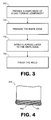
- FIG. 3 is a flowchart depicting an embodiment of method for repairing a gas turbine engine.
- FIG. 4 is schematic diagram depicting layers of IN-100 deposited on a knife edge.
- methods for repairing gas turbine engine knife edge seals are provided.
- several embodiments will be described that generally involve the use of powdered metal being melted and then deposited on the degraded end of a knife edge.
- the material is built-up as a series of thin layers that can be sequentially applied in order to rebuild the knife edge to suitable operational dimensions.
- at least some of these methods may be used with IN-100, which has previously eluded repair by welding techniques.
- FIG. 1 is a schematic diagram depicting a representative embodiment of a gas turbine engine 100 .
- engine 100 is configured as a turbofan, there is no intention to limit the invention to use with turbofans as use with other types of gas turbine engines is contemplated.
- engine 100 incorporates a fan 102 , a compressor section 104 , a combustion section 106 and a turbine section 108 .
- turbine section 108 includes alternating rows of stationary vanes 110 and rotating blades 112 .
- the blades are configured in sets, with each set being attached to a rotatable turbine disk.
- Disk 114 is an exemplary turbine disk that includes blades 116 .
- FIG. 2 is a schematic, partially cut-away view depicting a portion of disk 114 with the blades removed.
- disk 114 is configured to create a compound knife edge seal comprising two seals. Specifically, a first set of knife edges 202 forms a first of the seals, and a second set of knife edges 204 forms a second of the seals. Note also that when the blades (not shown) are in installed on the turbine disk, each of the blades also incorporates two knife edges that complete the two annular sets of knife edges that form the compound seal.
- knife edge seals of comparable configurations known as “hammer head seals”
- FIG. 3 is a flowchart depicting an embodiment of a method that may be used for repairing IN-100 components.
- IN-100 is a vacuum melted and investment cast nickel-base alloy recommended for high temperature applications of approximately 1850-1900.degree. F. IN-100 was developed by International Nickel Co., Inc.
- the material composition includes: chromium 8.0-11.0%, cobalt 13.0-17.0%, molybdenum 2.0-4.0%, vanadium 0.70-1.20%, titanium 4.50-5.00%, aluminum 5.0-6.0%, carbon 0.15-0.20%, boron 0.01-0.02%, zirconium 0.03-0.09%, iron 1.0% maximum, manganese 0.20% maximum, silicon 0.20% maximum, sulfur 0.015% maximum, with the remainder being nickel.
- the method may be construed as beginning at block 302 , in which a knife edge of a gas turbine component formed of IN-100 is provided. This can occur during an overhaul or repair procedure, for example, and may involve disassembly and/or cleaning of a turbine rotor, which includes the disk and attached blades.
- the knife edge can be prepared for welding (block 304 ). This can include grinding and/or blending of the knife edge so that a surface suitable to receive weld material is available.
- a cladding layer or layers are applied to the knife edge in order to build up a distal surface of the knife edge.
- a laser is used to melt IN-100 powder that is dispensed in a vicinity of the laser.
- the powder is injected co-axially into the laser beam so that the powder is melted and deposited on the knife edge.
- a maximum particle size of the powder is between 44 ⁇ m (325 standard mesh size) and 149 ⁇ m (100 standard mesh size).
- depositing of the material may be accomplished with an average power output of the laser of between 200 Watts and 1000 Watts, preferably between 300 Watts and 600 Watts.
- the function specified in block 306 is then repeated, as desired, to build up one or more layers of IN-100 material on the surface of the component.
- a maximum thickness of each of the layers in some embodiments is between 0.25 mm and 1.27 mm, preferably between 0.51 mm and 0.64 mm. Such thickness may be considered preferable due to the reduced heat required to produce welds of this thickness.
- the weld is finished, such as by grinding and/or blending, to a desired profile.
- An example of a repair accomplished by the embodiment of FIG. 3 is depicted in FIG. 4 .
- the distal end 402 of a knife edge 404 has been built-up with seven sequentially applied layers (e.g., layer 406 ) of material.
- layers e.g., layer 406
- a device with an integrated laser and powder applicator capable of 5-axis motion was used to provide the results depicted in FIG. 4 .
- various other devices could be used.
Landscapes
- Engineering & Computer Science (AREA)
- Physics & Mathematics (AREA)
- Optics & Photonics (AREA)
- Mechanical Engineering (AREA)
- Plasma & Fusion (AREA)
- General Engineering & Computer Science (AREA)
- Laser Beam Processing (AREA)
Abstract
Description
Claims (21)
Priority Applications (2)
| Application Number | Priority Date | Filing Date | Title |
|---|---|---|---|
| US11/782,057 US8089028B2 (en) | 2007-07-24 | 2007-07-24 | Methods for repairing gas turbine engine knife edge seals |
| EP08252526A EP2022597A1 (en) | 2007-07-24 | 2008-07-24 | Methods for repairing gas turbine engine knife edge seals |
Applications Claiming Priority (1)
| Application Number | Priority Date | Filing Date | Title |
|---|---|---|---|
| US11/782,057 US8089028B2 (en) | 2007-07-24 | 2007-07-24 | Methods for repairing gas turbine engine knife edge seals |
Publications (2)
| Publication Number | Publication Date |
|---|---|
| US20090026183A1 US20090026183A1 (en) | 2009-01-29 |
| US8089028B2 true US8089028B2 (en) | 2012-01-03 |
Family
ID=39874116
Family Applications (1)
| Application Number | Title | Priority Date | Filing Date |
|---|---|---|---|
| US11/782,057 Active 2030-11-01 US8089028B2 (en) | 2007-07-24 | 2007-07-24 | Methods for repairing gas turbine engine knife edge seals |
Country Status (2)
| Country | Link |
|---|---|
| US (1) | US8089028B2 (en) |
| EP (1) | EP2022597A1 (en) |
Cited By (2)
| Publication number | Priority date | Publication date | Assignee | Title |
|---|---|---|---|---|
| US9592573B2 (en) | 2013-03-13 | 2017-03-14 | Rolls-Royce Corporation | Laser deposition using a protrusion technique |
| US12209997B2 (en) | 2022-04-26 | 2025-01-28 | Rtx Corporation | Inspection systems and methods for sealing surfaces |
Families Citing this family (3)
| Publication number | Priority date | Publication date | Assignee | Title |
|---|---|---|---|---|
| US20080263863A1 (en) * | 2007-04-27 | 2008-10-30 | United Technologies Corporation | Dimensional restoration of turbine blade knife edge seals |
| US9283593B2 (en) * | 2011-01-13 | 2016-03-15 | Siemens Energy, Inc. | Selective laser melting / sintering using powdered flux |
| EP2802201B1 (en) | 2012-01-11 | 2017-07-12 | Vermeer Manufacturing Company | Wear-resistant cutting teeth, cutting heads and related apparatus |
Citations (20)
| Publication number | Priority date | Publication date | Assignee | Title |
|---|---|---|---|---|
| US4159410A (en) | 1977-06-13 | 1979-06-26 | General Electric Company | Method and apparatus for applying molten filler material |
| US4323756A (en) * | 1979-10-29 | 1982-04-06 | United Technologies Corporation | Method for fabricating articles by sequential layer deposition |
| US4426191A (en) | 1980-05-16 | 1984-01-17 | United Technologies Corporation | Flow directing assembly for a gas turbine engine |
| US4483054A (en) | 1982-11-12 | 1984-11-20 | United Technologies Corporation | Method for making a drum rotor |
| US4743165A (en) | 1986-10-22 | 1988-05-10 | United Technologies Corporation | Drum rotors for gas turbine engines |
| US4878953A (en) * | 1988-01-13 | 1989-11-07 | Metallurgical Industries, Inc. | Method of refurbishing cast gas turbine engine components and refurbished component |
| US4924581A (en) | 1988-11-22 | 1990-05-15 | Techniair, Inc. | Turbine air seal repair process |
| US5038014A (en) * | 1989-02-08 | 1991-08-06 | General Electric Company | Fabrication of components by layered deposition |
| US5071054A (en) * | 1990-12-18 | 1991-12-10 | General Electric Company | Fabrication of cast articles from high melting temperature superalloy compositions |
| US5374319A (en) * | 1990-09-28 | 1994-12-20 | Chromalloy Gas Turbine Corporation | Welding high-strength nickel base superalloys |
| US5449536A (en) * | 1992-12-18 | 1995-09-12 | United Technologies Corporation | Method for the application of coatings of oxide dispersion strengthened metals by laser powder injection |
| US6422815B1 (en) | 2000-03-02 | 2002-07-23 | General Electric Company | Turbine air seal replacement rings |
| US20040112280A1 (en) * | 2002-04-15 | 2004-06-17 | Thomas Beck | Method for producing monocrystalline structures |
| US6884964B2 (en) * | 2003-01-09 | 2005-04-26 | General Electric Company | Method of weld repairing a component and component repaired thereby |
| US20060065650A1 (en) * | 2004-09-30 | 2006-03-30 | Wen Guo | Compact coaxial nozzle for laser cladding |
| US20060168808A1 (en) * | 2005-02-03 | 2006-08-03 | United Technologies Corporation | Plasma ARC weld repair of IN100 material |
| US20060219329A1 (en) | 2005-03-29 | 2006-10-05 | Honeywell International, Inc. | Repair nickel-based superalloy and methods for refurbishment of gas turbine components |
| US20060219330A1 (en) * | 2005-03-29 | 2006-10-05 | Honeywell International, Inc. | Nickel-based superalloy and methods for repairing gas turbine components |
| US20070023402A1 (en) | 2005-07-26 | 2007-02-01 | United Technologies Corporation | Methods for repairing workpieces using microplasma spray coating |
| US20080135530A1 (en) * | 2006-12-11 | 2008-06-12 | General Electric Company | Method of modifying the end wall contour in a turbine using laser consolidation and the turbines derived therefrom |
Family Cites Families (3)
| Publication number | Priority date | Publication date | Assignee | Title |
|---|---|---|---|---|
| EP0861927A1 (en) * | 1997-02-24 | 1998-09-02 | Sulzer Innotec Ag | Method for manufacturing single crystal structures |
| EP1348781B1 (en) * | 2002-03-26 | 2004-12-15 | Sulzer Markets and Technology AG | Methode de croissance épitaxiale par irradiation avec un faisceau d'énergie |
| US7250081B2 (en) * | 2003-12-04 | 2007-07-31 | Honeywell International, Inc. | Methods for repair of single crystal superalloys by laser welding and products thereof |
-
2007
- 2007-07-24 US US11/782,057 patent/US8089028B2/en active Active
-
2008
- 2008-07-24 EP EP08252526A patent/EP2022597A1/en not_active Withdrawn
Patent Citations (22)
| Publication number | Priority date | Publication date | Assignee | Title |
|---|---|---|---|---|
| US4159410A (en) | 1977-06-13 | 1979-06-26 | General Electric Company | Method and apparatus for applying molten filler material |
| US4323756A (en) * | 1979-10-29 | 1982-04-06 | United Technologies Corporation | Method for fabricating articles by sequential layer deposition |
| US4426191A (en) | 1980-05-16 | 1984-01-17 | United Technologies Corporation | Flow directing assembly for a gas turbine engine |
| US4483054A (en) | 1982-11-12 | 1984-11-20 | United Technologies Corporation | Method for making a drum rotor |
| US4743165A (en) | 1986-10-22 | 1988-05-10 | United Technologies Corporation | Drum rotors for gas turbine engines |
| US4878953A (en) * | 1988-01-13 | 1989-11-07 | Metallurgical Industries, Inc. | Method of refurbishing cast gas turbine engine components and refurbished component |
| US4924581A (en) | 1988-11-22 | 1990-05-15 | Techniair, Inc. | Turbine air seal repair process |
| US5038014A (en) * | 1989-02-08 | 1991-08-06 | General Electric Company | Fabrication of components by layered deposition |
| US5374319A (en) * | 1990-09-28 | 1994-12-20 | Chromalloy Gas Turbine Corporation | Welding high-strength nickel base superalloys |
| US5071054A (en) * | 1990-12-18 | 1991-12-10 | General Electric Company | Fabrication of cast articles from high melting temperature superalloy compositions |
| US5449536A (en) * | 1992-12-18 | 1995-09-12 | United Technologies Corporation | Method for the application of coatings of oxide dispersion strengthened metals by laser powder injection |
| US6422815B1 (en) | 2000-03-02 | 2002-07-23 | General Electric Company | Turbine air seal replacement rings |
| US6565314B1 (en) | 2000-03-02 | 2003-05-20 | General Electric Company | Turbine air seal replacement rings |
| US20030103844A1 (en) | 2000-03-02 | 2003-06-05 | Marler Keith A. | Turbine air seal replacement rings |
| US20040112280A1 (en) * | 2002-04-15 | 2004-06-17 | Thomas Beck | Method for producing monocrystalline structures |
| US6884964B2 (en) * | 2003-01-09 | 2005-04-26 | General Electric Company | Method of weld repairing a component and component repaired thereby |
| US20060065650A1 (en) * | 2004-09-30 | 2006-03-30 | Wen Guo | Compact coaxial nozzle for laser cladding |
| US20060168808A1 (en) * | 2005-02-03 | 2006-08-03 | United Technologies Corporation | Plasma ARC weld repair of IN100 material |
| US20060219329A1 (en) | 2005-03-29 | 2006-10-05 | Honeywell International, Inc. | Repair nickel-based superalloy and methods for refurbishment of gas turbine components |
| US20060219330A1 (en) * | 2005-03-29 | 2006-10-05 | Honeywell International, Inc. | Nickel-based superalloy and methods for repairing gas turbine components |
| US20070023402A1 (en) | 2005-07-26 | 2007-02-01 | United Technologies Corporation | Methods for repairing workpieces using microplasma spray coating |
| US20080135530A1 (en) * | 2006-12-11 | 2008-06-12 | General Electric Company | Method of modifying the end wall contour in a turbine using laser consolidation and the turbines derived therefrom |
Non-Patent Citations (1)
| Title |
|---|
| Sun et al., "Direct Laser Deposition of Inconel 738 on directionally solidified Ni-base supperalloy component", Dec. 2005, SPIE, vol. 5629, pp. 84-92. * |
Cited By (2)
| Publication number | Priority date | Publication date | Assignee | Title |
|---|---|---|---|---|
| US9592573B2 (en) | 2013-03-13 | 2017-03-14 | Rolls-Royce Corporation | Laser deposition using a protrusion technique |
| US12209997B2 (en) | 2022-04-26 | 2025-01-28 | Rtx Corporation | Inspection systems and methods for sealing surfaces |
Also Published As
| Publication number | Publication date |
|---|---|
| EP2022597A1 (en) | 2009-02-11 |
| US20090026183A1 (en) | 2009-01-29 |
Similar Documents
| Publication | Publication Date | Title |
|---|---|---|
| JP4301402B2 (en) | How to repair a gas turbine engine stationary shroud using laser cladding | |
| US6491208B2 (en) | Cold spray repair process | |
| JP4318140B2 (en) | Method for repairing stationary shrouds of gas turbine engines using plasma transfer arc welding | |
| US8840366B2 (en) | Preforms and related methods for repairing abradable seals of gas turbine engines | |
| US6532656B1 (en) | Gas turbine engine compressor blade restoration method | |
| US7343676B2 (en) | Method of restoring dimensions of an airfoil and preform for performing same | |
| JP4901107B2 (en) | Method for repairing surfaces exposed to high pressure contact | |
| US5846057A (en) | Laser shock peening for gas turbine engine weld repair | |
| US5522134A (en) | Turbine vane flow area restoration method | |
| JPH0577721B2 (en) | ||
| US20130104397A1 (en) | Methods for repairing turbine blade tips | |
| JP2000220471A (en) | How to repair a high pressure turbine shroud | |
| CN102275058A (en) | Method for repairing gas turbine blades and a gas turbine blade | |
| JP7193617B2 (en) | Advance preparation for service runs and gas turbine component repairs | |
| US8089028B2 (en) | Methods for repairing gas turbine engine knife edge seals | |
| US20060219330A1 (en) | Nickel-based superalloy and methods for repairing gas turbine components | |
| US20060219329A1 (en) | Repair nickel-based superalloy and methods for refurbishment of gas turbine components | |
| CN109312624B (en) | Method for repairing a trailing edge of an airfoil to include a spout slot therein | |
| CN104675442B (en) | Turbine bucket with high hot hardness shroud cut deposit | |
| US20040261265A1 (en) | Method for improving the wear resistance of a support region between a turbine outer case and a supported turbine vane | |
| JP7524200B2 (en) | Welding and brazing techniques | |
| JP4496650B2 (en) | Steam turbine | |
| Liburdi et al. | Enabling Technologies for Advanced Turbine Component Life Extension | |
| JPWO2020154453A5 (en) |
Legal Events
| Date | Code | Title | Description |
|---|---|---|---|
| AS | Assignment |
Owner name: UNITED TECHNOLOGIES CORP., CONNECTICUT Free format text: ASSIGNMENT OF ASSIGNORS INTEREST;ASSIGNOR:ROSE, WILLIAM M.;REEL/FRAME:019602/0396 Effective date: 20070719 |
|
| AS | Assignment |
Owner name: UNITED TECHNOLOGIES CORP., CONNECTICUT Free format text: CORRECTIVE ASSIGNMENT TO CORRECT THE ASSIGNEE ADDRESS PREVIOUSLY RECORDED ON REEL 019602 FRAME 0396;ASSIGNOR:ROSE, WILLIAM M.;REEL/FRAME:019672/0082 Effective date: 20070719 Owner name: UNITED TECHNOLOGIES CORP., CONNECTICUT Free format text: CORRECTIVE ASSIGNMENT TO CORRECT THE ASSIGNEE ADDRESS PREVIOUSLY RECORDED ON REEL 019602 FRAME 0396. ASSIGNOR(S) HEREBY CONFIRMS THE 400 MAIN STREET EAST HARTFORD, CT 06108;ASSIGNOR:ROSE, WILLIAM M.;REEL/FRAME:019672/0082 Effective date: 20070719 |
|
| STCF | Information on status: patent grant |
Free format text: PATENTED CASE |
|
| CC | Certificate of correction | ||
| FPAY | Fee payment |
Year of fee payment: 4 |
|
| MAFP | Maintenance fee payment |
Free format text: PAYMENT OF MAINTENANCE FEE, 8TH YEAR, LARGE ENTITY (ORIGINAL EVENT CODE: M1552); ENTITY STATUS OF PATENT OWNER: LARGE ENTITY Year of fee payment: 8 |
|
| AS | Assignment |
Owner name: RAYTHEON TECHNOLOGIES CORPORATION, MASSACHUSETTS Free format text: CHANGE OF NAME;ASSIGNOR:UNITED TECHNOLOGIES CORPORATION;REEL/FRAME:054062/0001 Effective date: 20200403 |
|
| AS | Assignment |
Owner name: RAYTHEON TECHNOLOGIES CORPORATION, CONNECTICUT Free format text: CORRECTIVE ASSIGNMENT TO CORRECT THE AND REMOVE PATENT APPLICATION NUMBER 11886281 AND ADD PATENT APPLICATION NUMBER 14846874. TO CORRECT THE RECEIVING PARTY ADDRESS PREVIOUSLY RECORDED AT REEL: 054062 FRAME: 0001. ASSIGNOR(S) HEREBY CONFIRMS THE CHANGE OF ADDRESS;ASSIGNOR:UNITED TECHNOLOGIES CORPORATION;REEL/FRAME:055659/0001 Effective date: 20200403 |
|
| MAFP | Maintenance fee payment |
Free format text: PAYMENT OF MAINTENANCE FEE, 12TH YEAR, LARGE ENTITY (ORIGINAL EVENT CODE: M1553); ENTITY STATUS OF PATENT OWNER: LARGE ENTITY Year of fee payment: 12 |
|
| AS | Assignment |
Owner name: RTX CORPORATION, CONNECTICUT Free format text: CHANGE OF NAME;ASSIGNOR:RAYTHEON TECHNOLOGIES CORPORATION;REEL/FRAME:064714/0001 Effective date: 20230714 |