US8088938B2 - Low decomposition storage of a tantalum precursor - Google Patents
Low decomposition storage of a tantalum precursor Download PDFInfo
- Publication number
- US8088938B2 US8088938B2 US12/340,888 US34088808A US8088938B2 US 8088938 B2 US8088938 B2 US 8088938B2 US 34088808 A US34088808 A US 34088808A US 8088938 B2 US8088938 B2 US 8088938B2
- Authority
- US
- United States
- Prior art keywords
- precursor
- vessel
- withdrawing
- time
- tantalum
- Prior art date
- Legal status (The legal status is an assumption and is not a legal conclusion. Google has not performed a legal analysis and makes no representation as to the accuracy of the status listed.)
- Expired - Fee Related, expires
Links
- 239000002243 precursor Substances 0.000 title claims abstract description 122
- 238000000354 decomposition reaction Methods 0.000 title claims abstract description 21
- 229910052715 tantalum Inorganic materials 0.000 title claims abstract description 14
- GUVRBAGPIYLISA-UHFFFAOYSA-N tantalum atom Chemical compound [Ta] GUVRBAGPIYLISA-UHFFFAOYSA-N 0.000 title claims abstract description 12
- 238000003860 storage Methods 0.000 title claims description 38
- 239000000463 material Substances 0.000 claims abstract description 47
- 238000000034 method Methods 0.000 claims abstract description 32
- 230000007423 decrease Effects 0.000 claims abstract description 6
- ROSDSFDQCJNGOL-UHFFFAOYSA-N Dimethylamine Chemical compound CNC ROSDSFDQCJNGOL-UHFFFAOYSA-N 0.000 claims description 23
- 239000012159 carrier gas Substances 0.000 claims description 22
- 229910001220 stainless steel Inorganic materials 0.000 claims description 11
- 239000010935 stainless steel Substances 0.000 claims description 11
- XKRFYHLGVUSROY-UHFFFAOYSA-N Argon Chemical compound [Ar] XKRFYHLGVUSROY-UHFFFAOYSA-N 0.000 claims description 10
- 239000007789 gas Substances 0.000 claims description 10
- IJGRMHOSHXDMSA-UHFFFAOYSA-N Atomic nitrogen Chemical compound N#N IJGRMHOSHXDMSA-UHFFFAOYSA-N 0.000 claims description 9
- VYPSYNLAJGMNEJ-UHFFFAOYSA-N Silicium dioxide Chemical compound O=[Si]=O VYPSYNLAJGMNEJ-UHFFFAOYSA-N 0.000 claims description 9
- HPNMFZURTQLUMO-UHFFFAOYSA-N diethylamine Chemical compound CCNCC HPNMFZURTQLUMO-UHFFFAOYSA-N 0.000 claims description 8
- 239000000203 mixture Substances 0.000 claims description 8
- 229910052757 nitrogen Inorganic materials 0.000 claims description 8
- 238000010438 heat treatment Methods 0.000 claims description 7
- MZLGASXMSKOWSE-UHFFFAOYSA-N tantalum nitride Chemical compound [Ta]#N MZLGASXMSKOWSE-UHFFFAOYSA-N 0.000 claims description 7
- 239000011521 glass Substances 0.000 claims description 6
- 235000012239 silicon dioxide Nutrition 0.000 claims description 6
- 229910052786 argon Inorganic materials 0.000 claims description 5
- 239000001307 helium Substances 0.000 claims description 4
- 229910052734 helium Inorganic materials 0.000 claims description 4
- SWQJXJOGLNCZEY-UHFFFAOYSA-N helium atom Chemical compound [He] SWQJXJOGLNCZEY-UHFFFAOYSA-N 0.000 claims description 4
- BPUBBGLMJRNUCC-UHFFFAOYSA-N oxygen(2-);tantalum(5+) Chemical compound [O-2].[O-2].[O-2].[O-2].[O-2].[Ta+5].[Ta+5] BPUBBGLMJRNUCC-UHFFFAOYSA-N 0.000 claims description 4
- 229910001936 tantalum oxide Inorganic materials 0.000 claims description 4
- 125000004178 (C1-C4) alkyl group Chemical group 0.000 claims description 3
- XUIMIQQOPSSXEZ-UHFFFAOYSA-N Silicon Chemical compound [Si] XUIMIQQOPSSXEZ-UHFFFAOYSA-N 0.000 claims description 3
- GWEVSGVZZGPLCZ-UHFFFAOYSA-N Titan oxide Chemical compound O=[Ti]=O GWEVSGVZZGPLCZ-UHFFFAOYSA-N 0.000 claims description 3
- NRTOMJZYCJJWKI-UHFFFAOYSA-N Titanium nitride Chemical compound [Ti]#N NRTOMJZYCJJWKI-UHFFFAOYSA-N 0.000 claims description 3
- 239000010453 quartz Substances 0.000 claims description 3
- 239000010703 silicon Substances 0.000 claims description 3
- 229910052710 silicon Inorganic materials 0.000 claims description 3
- HBMJWWWQQXIZIP-UHFFFAOYSA-N silicon carbide Chemical compound [Si+]#[C-] HBMJWWWQQXIZIP-UHFFFAOYSA-N 0.000 claims description 3
- 229910010271 silicon carbide Inorganic materials 0.000 claims description 3
- 239000000377 silicon dioxide Substances 0.000 claims description 3
- OGIDPMRJRNCKJF-UHFFFAOYSA-N titanium oxide Inorganic materials [Ti]=O OGIDPMRJRNCKJF-UHFFFAOYSA-N 0.000 claims description 3
- -1 amino tantalum Chemical compound 0.000 claims description 2
- 238000000151 deposition Methods 0.000 description 14
- 230000008021 deposition Effects 0.000 description 12
- 238000000231 atomic layer deposition Methods 0.000 description 7
- 238000005229 chemical vapour deposition Methods 0.000 description 6
- 238000004519 manufacturing process Methods 0.000 description 6
- 230000008859 change Effects 0.000 description 5
- 239000010408 film Substances 0.000 description 5
- 238000000623 plasma-assisted chemical vapour deposition Methods 0.000 description 5
- 238000005240 physical vapour deposition Methods 0.000 description 4
- 239000004065 semiconductor Substances 0.000 description 4
- 238000004458 analytical method Methods 0.000 description 3
- 230000008901 benefit Effects 0.000 description 3
- 238000005137 deposition process Methods 0.000 description 3
- 229910052751 metal Inorganic materials 0.000 description 3
- 239000002184 metal Substances 0.000 description 3
- 230000008569 process Effects 0.000 description 3
- 239000000126 substance Substances 0.000 description 3
- 238000002411 thermogravimetry Methods 0.000 description 3
- 239000003039 volatile agent Substances 0.000 description 3
- 238000006243 chemical reaction Methods 0.000 description 2
- 239000010949 copper Substances 0.000 description 2
- 230000003247 decreasing effect Effects 0.000 description 2
- VSLPMIMVDUOYFW-UHFFFAOYSA-N dimethylazanide;tantalum(5+) Chemical compound [Ta+5].C[N-]C.C[N-]C.C[N-]C.C[N-]C.C[N-]C VSLPMIMVDUOYFW-UHFFFAOYSA-N 0.000 description 2
- 238000000921 elemental analysis Methods 0.000 description 2
- 230000008020 evaporation Effects 0.000 description 2
- 238000001704 evaporation Methods 0.000 description 2
- 238000012986 modification Methods 0.000 description 2
- 230000004048 modification Effects 0.000 description 2
- 239000012071 phase Substances 0.000 description 2
- RYGMFSIKBFXOCR-UHFFFAOYSA-N Copper Chemical compound [Cu] RYGMFSIKBFXOCR-UHFFFAOYSA-N 0.000 description 1
- 150000001336 alkenes Chemical class 0.000 description 1
- 230000004888 barrier function Effects 0.000 description 1
- 239000011248 coating agent Substances 0.000 description 1
- 238000000576 coating method Methods 0.000 description 1
- 238000010276 construction Methods 0.000 description 1
- 229910052802 copper Inorganic materials 0.000 description 1
- 125000002147 dimethylamino group Chemical group [H]C([H])([H])N(*)C([H])([H])[H] 0.000 description 1
- 125000001495 ethyl group Chemical group [H]C([H])([H])C([H])([H])* 0.000 description 1
- 238000011156 evaluation Methods 0.000 description 1
- 230000001747 exhibiting effect Effects 0.000 description 1
- 230000006698 induction Effects 0.000 description 1
- 230000007246 mechanism Effects 0.000 description 1
- 229910044991 metal oxide Inorganic materials 0.000 description 1
- 150000004706 metal oxides Chemical class 0.000 description 1
- 238000001465 metallisation Methods 0.000 description 1
- 150000004767 nitrides Chemical class 0.000 description 1
- JRZJOMJEPLMPRA-UHFFFAOYSA-N olefin Natural products CCCCCCCC=C JRZJOMJEPLMPRA-UHFFFAOYSA-N 0.000 description 1
- 125000002524 organometallic group Chemical group 0.000 description 1
- 230000009257 reactivity Effects 0.000 description 1
- 239000007787 solid Substances 0.000 description 1
- 229910001256 stainless steel alloy Inorganic materials 0.000 description 1
- 239000000758 substrate Substances 0.000 description 1
- PBCFLUZVCVVTBY-UHFFFAOYSA-N tantalum pentoxide Inorganic materials O=[Ta](=O)O[Ta](=O)=O PBCFLUZVCVVTBY-UHFFFAOYSA-N 0.000 description 1
- 239000010409 thin film Substances 0.000 description 1
- 239000012808 vapor phase Substances 0.000 description 1
Images


Classifications
-
- C—CHEMISTRY; METALLURGY
- C23—COATING METALLIC MATERIAL; COATING MATERIAL WITH METALLIC MATERIAL; CHEMICAL SURFACE TREATMENT; DIFFUSION TREATMENT OF METALLIC MATERIAL; COATING BY VACUUM EVAPORATION, BY SPUTTERING, BY ION IMPLANTATION OR BY CHEMICAL VAPOUR DEPOSITION, IN GENERAL; INHIBITING CORROSION OF METALLIC MATERIAL OR INCRUSTATION IN GENERAL
- C23C—COATING METALLIC MATERIAL; COATING MATERIAL WITH METALLIC MATERIAL; SURFACE TREATMENT OF METALLIC MATERIAL BY DIFFUSION INTO THE SURFACE, BY CHEMICAL CONVERSION OR SUBSTITUTION; COATING BY VACUUM EVAPORATION, BY SPUTTERING, BY ION IMPLANTATION OR BY CHEMICAL VAPOUR DEPOSITION, IN GENERAL
- C23C16/00—Chemical coating by decomposition of gaseous compounds, without leaving reaction products of surface material in the coating, i.e. chemical vapour deposition [CVD] processes
- C23C16/44—Chemical coating by decomposition of gaseous compounds, without leaving reaction products of surface material in the coating, i.e. chemical vapour deposition [CVD] processes characterised by the method of coating
- C23C16/4401—Means for minimising impurities, e.g. dust, moisture or residual gas, in the reaction chamber
- C23C16/4404—Coatings or surface treatment on the inside of the reaction chamber or on parts thereof
-
- C—CHEMISTRY; METALLURGY
- C23—COATING METALLIC MATERIAL; COATING MATERIAL WITH METALLIC MATERIAL; CHEMICAL SURFACE TREATMENT; DIFFUSION TREATMENT OF METALLIC MATERIAL; COATING BY VACUUM EVAPORATION, BY SPUTTERING, BY ION IMPLANTATION OR BY CHEMICAL VAPOUR DEPOSITION, IN GENERAL; INHIBITING CORROSION OF METALLIC MATERIAL OR INCRUSTATION IN GENERAL
- C23C—COATING METALLIC MATERIAL; COATING MATERIAL WITH METALLIC MATERIAL; SURFACE TREATMENT OF METALLIC MATERIAL BY DIFFUSION INTO THE SURFACE, BY CHEMICAL CONVERSION OR SUBSTITUTION; COATING BY VACUUM EVAPORATION, BY SPUTTERING, BY ION IMPLANTATION OR BY CHEMICAL VAPOUR DEPOSITION, IN GENERAL
- C23C16/00—Chemical coating by decomposition of gaseous compounds, without leaving reaction products of surface material in the coating, i.e. chemical vapour deposition [CVD] processes
- C23C16/44—Chemical coating by decomposition of gaseous compounds, without leaving reaction products of surface material in the coating, i.e. chemical vapour deposition [CVD] processes characterised by the method of coating
- C23C16/448—Chemical coating by decomposition of gaseous compounds, without leaving reaction products of surface material in the coating, i.e. chemical vapour deposition [CVD] processes characterised by the method of coating characterised by the method used for generating reactive gas streams, e.g. by evaporation or sublimation of precursor materials
- C23C16/4481—Chemical coating by decomposition of gaseous compounds, without leaving reaction products of surface material in the coating, i.e. chemical vapour deposition [CVD] processes characterised by the method of coating characterised by the method used for generating reactive gas streams, e.g. by evaporation or sublimation of precursor materials by evaporation using carrier gas in contact with the source material
Definitions
- This invention relates generally to the fields of semiconductor, photovoltaic, flat panel, or LCD-TFT device fabrication.
- organometallic molecules or “precursors” are being proposed as metal sources for depositing metal, metal oxide, and metal nitride layers for semiconductor manufacture. Typically, these materials are used for depositing thin film layers on substrates. Depositions of these materials may be carried out by several methods, including: chemical vapor deposition (CVD), plasma enhanced chemical vapor deposition (PECVD), physical vapor deposition (PVD), atomic layer deposition (ALD) or plasma enhanced atomic layer deposition (PEALD). These precursors need particular physical and thermal properties to be used in a given semiconductor manufacturing process. For example, the precursors need to have high volatility, reactivity, and thermal stability.
- CVD chemical vapor deposition
- PECVD plasma enhanced chemical vapor deposition
- PVD physical vapor deposition
- ALD atomic layer deposition
- PEALD plasma enhanced atomic layer deposition
- Other known precursors for the deposition of tantalum nitride include “PDEAT” (pentakis(diethlyamino)tantalum), and “PEMAT” pentakis(N-methlyethylamino)tantalum. These precursors may be reacted with NH 3 to produce a highly uniform films with low resistivity, which may be used as a barrier layer to prevent copper (Cu) metallization.
- a precursor since the precursor is delivered to the deposition chamber in the gas phase, a precursor must have a sufficient vapor pressure to provide enough material for uniform deposition. However, most of the precursors for these films are solids at room temperature where they have low vapor pressures. This then requires the delivery temperature of the precursor to be higher than room temperature. For example with PDMAT, this temperature is often approximately 75° C. Thus, an important property of the precursor is the thermal stability of the precursor at this elevated temperature. If a precursor decomposes prior to deposition, the resulting films are often contaminated or non-uniform. In addition to this thermal stability, material compatibility is often an issue. A precursor must be compatible with the material that the chemical is delivered or stored in. In addition, the precursors are often delivered with a carrier gas such as argon (Ar) or nitrogen (N 2 ) often at reduced pressures.
- a carrier gas such as argon (Ar) or nitrogen (N 2 ) often at reduced pressures.
- a method for storing a precursor which decreases the precursor decomposition rate comprises providing a vessel, which itself comprises an outer surface made of a first material, and an inner surface made of a second material.
- the vessel defines an internal volume, and the outer surface material is not the same as the inner surface material.
- a precursor is introduced into the vessel, where the precursor is of the general formula: Ta(NR 1 R 2 ) x ; where R 1 and R 2 are independently selected among C1-C4 alkyl groups, and x is 4 or 5. While in the vessel, at least part of the precursor is in direct physical contact with at least part of the inner surface material.
- the vessel is heated to a temperature between about 60° C. and about 150° C., and at least part of the precursor is withdrawn from the vessel.
- FIG. 1 illustrates a schematic representation according to one embodiment of the current invention
- FIG. 2 illustrates experimental data relating to a precursor material
- FIG. 3 also illustrates experimental data relating to a precursor material
- FIG. 4 illustrates experimental data, obtained according to one embodiment of the current invention.
- FIG. 5 illustrates experimental data, as obtained according to one embodiment of the current invention.
- a method for storing a precursor which decreases the precursor decomposition rate comprises providing a vessel, which itself comprises an outer surface made of a first material, and an inner surface made of a second material.
- the vessel defines an internal volume, and the outer surface material is not the same as the inner surface material.
- a precursor is introduced into the vessel, where the precursor is of the general formula: Ta(NR 1 R 2 ) x ; where R 1 and R 2 are independently selected among C1-C4 alkyl groups, and x is 4 or 5. While in the vessel, at least part of the precursor is in direct physical contact with at least part of the inner surface material.
- the vessel is heated to a temperature between about 60° C. and about 150° C., and at least part of the precursor is withdrawn from the vessel.
- the tantalum containing precursor is Ta(NMe 2 ) 5 (PDMAT) which is a precursor material used for the deposition of tantalum oxide (e.g. Ta 2 O 5 ) and tantalum nitride (e.g. TaN) films.
- the precursor may be Ta[N(CH 2 CH 3 ) 2 ] 5 (PDEAT), or Ta[N(CH 2 CH 3 )(CH 3 )] 5 (PEMAT).
- the deposition process requires that these materials be delivered to the reaction chamber in the gas phase (e.g for use in a CVD or ALD type process).
- PDMAT has vapor pressure of about 0.2 Torr at 80° C., and about 1 Torr at about 100° C.
- precursors such as these are supplied and stored in canisters made of materials such as 316 L stainless steel.
- a precursor storage vessel 100 is shown.
- the storage vessel 100 has at least one outer surface 101 made of a first material, and at least one inner surface 102 made of a second material.
- the material of the inner surface 102 and the outer surface 101 are not the same.
- the outer surface material may be stainless steel (e.g. 316 L type stainless steel).
- the inner surface 102 material may be one or more of glass, silicon, silicon dioxide, silicon carbide, quartz, titanium oxide, titanium nitride PFTE, tantalum oxide, and tantalum nitride.
- the inner surface material may be applied conventionally as a coating, or it may be supplied as an insert type material, as would be known to one of skill in the art.
- the vessel also defines an internal volume 103 , into which a precursor 104 may be introduced for storage.
- the precursor 104 is situated inside the internal volume 103 of the storage vessel 100 such that at least part of the precursor 104 is in direct physical contact (e.g. touching) with the inner surface 102 .
- the vessel 100 may be heated to a temperature between about 60° C. and about 150° C. with heating element 105 .
- Heating element 105 may be a conventional heating element, such as a resistance header or an induction heater, as would be known of one of skill in the art.
- the deposition process may be one of chemical vapor deposition (CVD), plasma enhanced chemical vapor deposition (PECVD), physical vapor deposition (PVD), atomic layer deposition (ALD) or plasma enhanced atomic layer deposition (PEALD).
- CVD chemical vapor deposition
- PECVD plasma enhanced chemical vapor deposition
- PVD physical vapor deposition
- ALD atomic layer deposition
- PEALD plasma enhanced atomic layer deposition
- a carrier gas is introduced into the vessel 100 from a carrier gas supply source.
- the carrier gas may be flowed through the vessel 100 to carry the vapor phase of the precursor 104 to the deposition chamber 106 .
- the carrier gas may be nitrogen, argon, helium, or mixtures of these.
- the carrier gas may also be dimethylamine (DMA) or diethylamine (DEA), or mixtures of these with each other or nitrogen, argon, or helium.
- carrier gas may be a gas mixture comprising 0% to 100% dimethylamine or diethylamine.
- the carrier 12 gas may be introduced from the carrier gas source 107 at pressures between about 1 mTorr and about 760 Torr, and at various flow rates (e.g. between about 100 sccm and about 2000 sccm).
- a carrier gas type mixture containing dimethylamine or diethylamine may also be used as a head gas for storage of the precursor 104 .
- the mixture may be added to the vessel 100 so that precursor 104 is then stored under a blanket of dimethylamine or diethylamine (e.g. in an atmosphere containing dimethylamine or diethylamine).
- dimethylamine or diethylamine are used in a carrier gas or in a head gas, the addition of these would shift the equilibrium of the precursor's decomposition reaction towards the nondecomposed molecule, thereby allowing for a decrease in the decomposition rate of the precursor 104 stored in the storage vessel 100 .
- a period of time passes between when the precursor 104 is introduced into the internal volume 103 of the storage vessel 100 , and when at least part of the precursor 104 is withdrawn (for instance, to be sent to deposition chamber 106 ).
- This period of time may correspond to a shipping or transit time when the storage vessel 100 is transferred from a chemical manufacturer or supplier's site to an end user or customers' site, or this period of time may correspond to a period of inactivity when deposition chamber 106 is inactive. In some embodiments, this time period may be between 1 day and 30 days, or in some embodiments the time period may be greater than 14 days.
- the precursor 104 stored in the vessel 100 exhibits a decreased decomposition rate.
- the precursor 104 has decomposed less than 7.0%, as evidenced by weight change, during the time between when the precursor 104 is introduced into the storage vessel, and the time when the precursor is withdrawn. In some embodiments, the amount of decomposition is less than 5.0%, by weight, or less than 1.0%, by weight.
- a plurality of storage surfaces 107 may be provided in the internal volume 103 of the storage vessel 100 .
- These storage surfaces 107 may be made of a non-stainless steel material, for instance, they may be made of the same material as the inner surface 102 .
- Storage surfaces 107 may be of varying shapes and configurations, but generally when precursor 104 is disposed on storage surfaces 107 , the overall surface area of the precursor 104 that is exposed to either the carrier gas or head gas, is increased, thereby allowing a greater rate of precursor withdraw from the storage vessel 100 .
- storage surfaces may be flat surfaces, such as disks or trays, which are inserted into the internal volume 103 of the storage vessel 100 .
- the storage surfaces may machined as part of, or affixed to the inner surface 102 of the storage vessel 100 .
- the storage vessel 100 may be a bubbler type vessel.
- a bubbler vessel is described as a stainless steel canister (most likely 316 L electropolished ultrahigh purity) in which there is an inlet tube for the carrier gas and an outlet tube for the carrier gas+precursor vapors to exit (inlet and outlet tubes may also have a valves ( 108 , 109 ) for opening and closing the flow of gas).
- the inlet tube may be heated to the same temperature as the canister and the outlet tube may be heated to higher than the canister.
- Bubbler type vessels are offered by companies such as Air Liquide and are conventionally referred to as precursor bubblers.
- the storage vessel 100 may be a precursor storage container.
- precursor storage containers are similar to bubblers in that they are stainless steel canisters with inlets and outlets, suitable to store a precursor.
- Precursor storage containers may differ from bubblers in that bubblers are typically semi-permanent components in precursor delivery systems (e.g. a component affixed at a customer location), while precursor storage containers are intended to be transferred between locations (e.g. between a chemical supplier's facility and the customer facility).
- TGA thermal gravimetric analysis
- Example 2 Samples of PDMAT were placed in vessels and heated over a 2 week period as in Example 2. Once a day, any volatiles were removed from the vessel with a vacuum pump. After 2 weeks, the samples were removed and subjected to an elemental analysis ( ⁇ 0.05% relative error), the results of which were compared to the baseline sample of PDMAT from Example 2. It was determined that the sample in vessel 2 underwent little to no decomposition, while the sample in vessel 1 exhibited approximately a 13% relative change as compared to the baseline sample. Comparing the results in Example 1, with those in Example 2, it was determined that the removal of the volatiles (e.g. NHMe 2 ) enhances the overall decomposition rate. The results of this analysis are shown in Table 2:
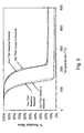
- Example 2 Samples of PDMAT were placed in vessels as in Example 2. These samples were heated and maintained at a temperature of about 75° C., and volatiles were continuously evacuated with a vacuum pump over a period of 2 days. After 2 days, the samples were removed and analyzed under a TGA analysis as in Example 1.
- a derivative test, “dTG” was also performed on the samples under sub-atmospheric conditions.
- the sample in vessel 1 i.e. stainless steel vessel
- the sample in vessel 1 i.e. stainless steel vessel
- the sample in vessel 2 i.e. glass lined vessel
- the dTG test showed little evidence of the presence of multiple species.
- the results for vessels 1 and 2 are shown in FIGS. 3 and 4 , respectively.
- FIG. 5 shows graphically the results, which are interpreted to show that even after 2 days of continuous treatment, the sample in vessel 2 (i.e. glass lined) exhibits similar properties as those in the baseline sample.
Abstract
Description
Ta(NR1R2)x;
where R1 and R2 are independently selected among C1-C4 alkyl groups, and x is 4 or 5. While in the vessel, at least part of the precursor is in direct physical contact with at least part of the inner surface material. The vessel is heated to a temperature between about 60° C. and about 150° C., and at least part of the precursor is withdrawn from the vessel.
-
- withdrawing at least part of the precursor from the vessel, wherein the amount of precursor in the vessel has decomposed less than 7.0%, by weight, between the time the precursor is introduced into the vessel, and the time the precursor is withdrawn from the vessel;
- withdrawing at least part of the precursor from the vessel, wherein the amount of precursor in the vessel has decomposed less than 5.0%, by weight, between the time the precursor is introduced into the vessel, and the time the precursor is withdrawn from the vessel;
- withdrawing at least part of the precursor from the vessel, wherein the amount of precursor in the vessel has decomposed less than 1.0%, by weight, between the time the precursor is introduced into the vessel, and the time the precursor is withdrawn from the vessel;
- allowing at least 14 days to pass between the time the precursor is introduced into the vessel, and the time when the precursor is withdrawn from the vessel;
- introducing a carrier gas to the vessel, where the carrier gas is one of nitrogen, argon, helium, dimethylamine (DMA), diethylamine (DEA), and mixtures thereof;
- introducing the carrier gas into the vessel to aid in withdrawing the precursor;
- introducing the carrier gas into the vessel to act as a head gas for storage of the precursor in the vessel;
- withdrawing the precursor from the from the vessel at pressure between about 1 mTorr and about 760 Torr, preferably between about 1 Torr and about 10 Torr, and more preferably at a pressure of about 0.5 Torr.
- heating the vessel to a temperature between about 60° C. and about 100° C., and preferably to about 75° C.;
- the precursor is at least one of pentakis(dimethyl)amino tantalum (PDMAT), pentakis(diethlyamino)tantalum (PDEAT), and pentakis(N-methlyethylamino)tantalum (PEMAT);
- the outer surface material is stainless steel, or a stainless steel alloy;
- the inner surface material is selected from glass, silicon, silicon dioxide, silicon carbide, quartz, titanium oxide, titanium nitride PFTE, tantalum oxide, and tantalum nitride.
- providing a plurality of storage surfaces disposed within the internal volume of the vessel; and introducing the precursor such that at least part of the precursor is in direct physical contact with at least part of the storage surfaces, wherein, the storage surfaces are made of a material different from that of the outer surface material.
- the vessel is a bubbler type vessel; and
- the vessel is a precursor storage container.
Ta(NR1R2)x;
where R1 and R2 are independently selected among C1-C4 alkyl groups, and x is 4 or 5. While in the vessel, at least part of the precursor is in direct physical contact with at least part of the inner surface material. The vessel is heated to a temperature between about 60° C. and about 150° C., and at least part of the precursor is withdrawn from the vessel.
Ta(NR2)5→Ta(NR2)4+NR2→RN:Ta(NR2)3+HNR2+(RH,olefin),
where R may independently be =(NMe2, NEt2, NPr2, NBU2, and NMeBu). While this decomposition is complicated, it is clear that a change (over time) in the % C, % N or % H observed would be an indication of decomposition at least because of the release of HNR2. Likewise, lack of a change (over time) in the % C, % N, or % H would be indicative of a lack of, or of a very low, decomposition rate.
| TABLE 1 | |||||
| Sample | % C | % H | % N | ||
| Baseline sample | 29.51 | 7.04 | 16.23 | ||
| |
27.33 | 6.39 | 14.46 | ||
| |
29.96 | 7.26 | 16.74 | ||
| TABLE 2 | |||
| Sample | % C | % H | % N |
| Baseline sample | 29.51 | 7.04 | 16.23 |
| |
26.17 | 6.14 | 14.73 |
| |
28.63 | 6.77 | 16.08 |
Claims (19)
Ta(NR1R2)x
Priority Applications (2)
| Application Number | Priority Date | Filing Date | Title |
|---|---|---|---|
| PCT/IB2008/055495 WO2009081380A2 (en) | 2007-12-21 | 2008-12-22 | Low decomposition storage of a tantalum precursor |
| US12/340,888 US8088938B2 (en) | 2007-12-21 | 2008-12-22 | Low decomposition storage of a tantalum precursor |
Applications Claiming Priority (3)
| Application Number | Priority Date | Filing Date | Title |
|---|---|---|---|
| US1591607P | 2007-12-21 | 2007-12-21 | |
| US1590507P | 2007-12-21 | 2007-12-21 | |
| US12/340,888 US8088938B2 (en) | 2007-12-21 | 2008-12-22 | Low decomposition storage of a tantalum precursor |
Publications (2)
| Publication Number | Publication Date |
|---|---|
| US20090163732A1 US20090163732A1 (en) | 2009-06-25 |
| US8088938B2 true US8088938B2 (en) | 2012-01-03 |
Family
ID=40671209
Family Applications (1)
| Application Number | Title | Priority Date | Filing Date |
|---|---|---|---|
| US12/340,888 Expired - Fee Related US8088938B2 (en) | 2007-12-21 | 2008-12-22 | Low decomposition storage of a tantalum precursor |
Country Status (3)
| Country | Link |
|---|---|
| US (1) | US8088938B2 (en) |
| TW (1) | TWI440737B (en) |
| WO (1) | WO2009081380A2 (en) |
Families Citing this family (1)
| Publication number | Priority date | Publication date | Assignee | Title |
|---|---|---|---|---|
| WO2018111720A1 (en) * | 2016-12-12 | 2018-06-21 | Applied Materials, Inc. | Precursor control system and process |
Citations (3)
| Publication number | Priority date | Publication date | Assignee | Title |
|---|---|---|---|---|
| WO2004007793A2 (en) | 2002-07-17 | 2004-01-22 | Applied Materials, Inc. | Method and apparatus for providing gas to a processing chamber |
| WO2007115000A2 (en) | 2006-03-30 | 2007-10-11 | Applied Materials, Inc. | Chemical delivery apparatus for cvd or ald |
| EP1865091A2 (en) | 2006-06-09 | 2007-12-12 | Air Products and Chemicals, Inc. | High flow GaCI3 delivery |
-
2008
- 2008-12-22 US US12/340,888 patent/US8088938B2/en not_active Expired - Fee Related
- 2008-12-22 WO PCT/IB2008/055495 patent/WO2009081380A2/en active Application Filing
- 2008-12-22 TW TW097150022A patent/TWI440737B/en active
Patent Citations (3)
| Publication number | Priority date | Publication date | Assignee | Title |
|---|---|---|---|---|
| WO2004007793A2 (en) | 2002-07-17 | 2004-01-22 | Applied Materials, Inc. | Method and apparatus for providing gas to a processing chamber |
| WO2007115000A2 (en) | 2006-03-30 | 2007-10-11 | Applied Materials, Inc. | Chemical delivery apparatus for cvd or ald |
| EP1865091A2 (en) | 2006-06-09 | 2007-12-12 | Air Products and Chemicals, Inc. | High flow GaCI3 delivery |
Non-Patent Citations (6)
| Title |
|---|
| Bradley D.C., et al. "Metallo-organic compounds containing metal-nitrogen bonds". Canadian Journal of Chemistry (1962), 40, 1355-60. |
| International Search Report for PCT/IB2008/055495 and Written Opinion. |
| IPRP for related PCT/IB2008/055495, (2009). |
| Koyoma, H. et al. "Thermal properties of various Ta precursors used in chemical vapor deposition of tantalum pentoxide." Japan Journal of Applied Physics, vol. 33, Nov. 1994, pp. 6291-6298. |
| Maeng, W. et al. "Atomic layer deposition of Ta-based thin films: Reactions of alkylamide precursor with various reactants." Journal of Vacuum Science and Technology: Part B, AVS/AIP, vol. 24, No. 5, Sep. 18, 2006, pp. 2276-2281. |
| Winter, C. "The chemical vapor deposition of metal nitride films using modern metalorganic precursors." Aldrichimica ACTA, vol. 33, No. 1, 2000, pp. 2-12. |
Also Published As
| Publication number | Publication date |
|---|---|
| TWI440737B (en) | 2014-06-11 |
| WO2009081380A2 (en) | 2009-07-02 |
| TW200936799A (en) | 2009-09-01 |
| US20090163732A1 (en) | 2009-06-25 |
| WO2009081380A3 (en) | 2009-12-23 |
Similar Documents
| Publication | Publication Date | Title |
|---|---|---|
| US10995405B2 (en) | Deposition of molybdenum thin films using a molybdenum carbonyl precursor | |
| US10077364B2 (en) | Organoaminodisilane precursors and methods for depositing films comprising same | |
| US9196474B2 (en) | Metal amide deposition precursors and their stabilization with an inert ampoule liner | |
| TWI636987B (en) | Aza-polysilane precursors and methods for depositing films comprising same | |
| US20160307708A1 (en) | Tantalum-containing film forming compositions and vapor deposition of tantalum-containing films | |
| US7678422B2 (en) | Cyclic chemical vapor deposition of metal-silicon containing films | |
| US10584039B2 (en) | Titanium-containing film forming compositions for vapor deposition of titanium-containing films | |
| TW201833123A (en) | Zirconium, hafnium, titanium precursors and deposition of group 4 containing films using the same | |
| EP3359705A1 (en) | Methods for depositing a conformal metal or metalloid silicon nitride film | |
| US11168099B2 (en) | Titanium-containing film forming compositions for vapor deposition of titanium-containing films | |
| US9691770B2 (en) | Vanadium-containing film forming compositions and vapor deposition of vanadium-containing films | |
| US20110244681A1 (en) | Method of forming a tantalum-containing layer on a substrate | |
| US20160083405A1 (en) | Tantalum- or vanadium-containing film forming compositions and vapor deposition of tantalum- or vanadium-containing films | |
| US8088938B2 (en) | Low decomposition storage of a tantalum precursor | |
| WO2017115138A1 (en) | Cobalt-containing film forming compositions, their synthesis, and use in film deposition | |
| US20220411930A1 (en) | Compounds And Methods For Selectively Forming Metal-Containing Films | |
| US20230108732A1 (en) | Methods Of Selectively Forming Metal-Containing Films | |
| US20210221830A1 (en) | Methods for vapor deposition of group 4 transition metal-containing films using group 4 transition metal-containing films forming compositions | |
| KR20210041884A (en) | Apparatus for depositing thin film and method for depositing thin film | |
| JP2013104100A (en) | Method for depositing metallic thin film and raw material for depositing metallic thin film |
Legal Events
| Date | Code | Title | Description |
|---|---|---|---|
| AS | Assignment |
Owner name: AMERICAN AIR LIQUIDE, INC.,CALIFORNIA Free format text: ASSIGNMENT OF ASSIGNORS INTEREST;ASSIGNOR:STAFFORD, NATHAN;REEL/FRAME:022367/0056 Effective date: 20090216 Owner name: AIR LIQUIDE ELECTRONICS U.S. LP,TEXAS Free format text: ASSIGNMENT OF ASSIGNORS INTEREST;ASSIGNORS:LETESSIER, OLIVIER;LAXMAN, RAVI K.;REEL/FRAME:022367/0097 Effective date: 20090216 Owner name: AMERICAN AIR LIQUIDE, INC.,CALIFORNIA Free format text: ASSIGNMENT OF ASSIGNORS INTEREST;ASSIGNOR:DUSSARRAT, CHRISTIAN;REEL/FRAME:022367/0115 Effective date: 20090216 Owner name: AMERICAN AIR LIQUIDE, INC., CALIFORNIA Free format text: ASSIGNMENT OF ASSIGNORS INTEREST;ASSIGNOR:DUSSARRAT, CHRISTIAN;REEL/FRAME:022367/0115 Effective date: 20090216 Owner name: AIR LIQUIDE ELECTRONICS U.S. LP, TEXAS Free format text: ASSIGNMENT OF ASSIGNORS INTEREST;ASSIGNORS:LETESSIER, OLIVIER;LAXMAN, RAVI K.;REEL/FRAME:022367/0097 Effective date: 20090216 Owner name: AMERICAN AIR LIQUIDE, INC., CALIFORNIA Free format text: ASSIGNMENT OF ASSIGNORS INTEREST;ASSIGNOR:STAFFORD, NATHAN;REEL/FRAME:022367/0056 Effective date: 20090216 |
|
| ZAAA | Notice of allowance and fees due |
Free format text: ORIGINAL CODE: NOA |
|
| ZAAB | Notice of allowance mailed |
Free format text: ORIGINAL CODE: MN/=. |
|
| STCF | Information on status: patent grant |
Free format text: PATENTED CASE |
|
| FEPP | Fee payment procedure |
Free format text: PAYOR NUMBER ASSIGNED (ORIGINAL EVENT CODE: ASPN); ENTITY STATUS OF PATENT OWNER: LARGE ENTITY |
|
| FPAY | Fee payment |
Year of fee payment: 4 |
|
| MAFP | Maintenance fee payment |
Free format text: PAYMENT OF MAINTENANCE FEE, 8TH YEAR, LARGE ENTITY (ORIGINAL EVENT CODE: M1552); ENTITY STATUS OF PATENT OWNER: LARGE ENTITY Year of fee payment: 8 |
|
| FEPP | Fee payment procedure |
Free format text: MAINTENANCE FEE REMINDER MAILED (ORIGINAL EVENT CODE: REM.); ENTITY STATUS OF PATENT OWNER: LARGE ENTITY |
|
| LAPS | Lapse for failure to pay maintenance fees |
Free format text: PATENT EXPIRED FOR FAILURE TO PAY MAINTENANCE FEES (ORIGINAL EVENT CODE: EXP.); ENTITY STATUS OF PATENT OWNER: LARGE ENTITY |
|
| STCH | Information on status: patent discontinuation |
Free format text: PATENT EXPIRED DUE TO NONPAYMENT OF MAINTENANCE FEES UNDER 37 CFR 1.362 |
|
| FP | Lapsed due to failure to pay maintenance fee |
Effective date: 20240103 |