US8087709B2 - Pickup truck bed extender - Google Patents
Pickup truck bed extender Download PDFInfo
- Publication number
- US8087709B2 US8087709B2 US12/928,922 US92892210A US8087709B2 US 8087709 B2 US8087709 B2 US 8087709B2 US 92892210 A US92892210 A US 92892210A US 8087709 B2 US8087709 B2 US 8087709B2
- Authority
- US
- United States
- Prior art keywords
- bed
- floor
- truck
- extender
- tailgate
- Prior art date
- Legal status (The legal status is an assumption and is not a legal conclusion. Google has not performed a legal analysis and makes no representation as to the accuracy of the status listed.)
- Expired - Fee Related
Links
- 239000004606 Fillers/Extenders Substances 0.000 title claims abstract description 72
- 230000000712 assembly Effects 0.000 claims abstract description 16
- 238000000429 assembly Methods 0.000 claims abstract description 16
- 210000005069 ears Anatomy 0.000 claims abstract description 8
- 230000008878 coupling Effects 0.000 abstract description 2
- 238000010168 coupling process Methods 0.000 abstract description 2
- 238000005859 coupling reaction Methods 0.000 abstract description 2
- 238000003780 insertion Methods 0.000 description 3
- 230000037431 insertion Effects 0.000 description 3
- 238000009434 installation Methods 0.000 description 3
- 229910052751 metal Inorganic materials 0.000 description 3
- 239000002184 metal Substances 0.000 description 3
- 230000007812 deficiency Effects 0.000 description 2
- -1 e.g. Substances 0.000 description 2
- 238000012986 modification Methods 0.000 description 2
- 230000004048 modification Effects 0.000 description 2
- 239000011120 plywood Substances 0.000 description 2
- 229910000831 Steel Inorganic materials 0.000 description 1
- 229910052782 aluminium Inorganic materials 0.000 description 1
- XAGFODPZIPBFFR-UHFFFAOYSA-N aluminium Chemical compound [Al] XAGFODPZIPBFFR-UHFFFAOYSA-N 0.000 description 1
- 230000003467 diminishing effect Effects 0.000 description 1
- 238000005553 drilling Methods 0.000 description 1
- 238000004519 manufacturing process Methods 0.000 description 1
- 230000013011 mating Effects 0.000 description 1
- 239000010959 steel Substances 0.000 description 1
- 239000002023 wood Substances 0.000 description 1
Images


Classifications
-
- B—PERFORMING OPERATIONS; TRANSPORTING
- B62—LAND VEHICLES FOR TRAVELLING OTHERWISE THAN ON RAILS
- B62D—MOTOR VEHICLES; TRAILERS
- B62D33/00—Superstructures for load-carrying vehicles
- B62D33/08—Superstructures for load-carrying vehicles comprising adjustable means
-
- B—PERFORMING OPERATIONS; TRANSPORTING
- B60—VEHICLES IN GENERAL
- B60P—VEHICLES ADAPTED FOR LOAD TRANSPORTATION OR TO TRANSPORT, TO CARRY, OR TO COMPRISE SPECIAL LOADS OR OBJECTS
- B60P3/00—Vehicles adapted to transport, to carry or to comprise special loads or objects
- B60P3/40—Vehicles adapted to transport, to carry or to comprise special loads or objects for carrying long loads, e.g. with separate wheeled load supporting elements
-
- B—PERFORMING OPERATIONS; TRANSPORTING
- B60—VEHICLES IN GENERAL
- B60R—VEHICLES, VEHICLE FITTINGS, OR VEHICLE PARTS, NOT OTHERWISE PROVIDED FOR
- B60R9/00—Supplementary fittings on vehicle exterior for carrying loads, e.g. luggage, sports gear or the like
- B60R9/06—Supplementary fittings on vehicle exterior for carrying loads, e.g. luggage, sports gear or the like at vehicle front or rear
-
- B—PERFORMING OPERATIONS; TRANSPORTING
- B62—LAND VEHICLES FOR TRAVELLING OTHERWISE THAN ON RAILS
- B62D—MOTOR VEHICLES; TRAILERS
- B62D33/00—Superstructures for load-carrying vehicles
- B62D33/02—Platforms; Open load compartments
- B62D33/023—Sideboard or tailgate structures
- B62D33/027—Sideboard or tailgate structures movable
- B62D33/0273—Movable tailboards for vehicles comprising non-movable sideboards, e.g. pick-up trucks
Definitions
- the present invention relates to an apparatus for providing a greater load-bearing surface for a pickup truck bed, and in particular to a pickup truck bed extender that can be quickly attached and removed from a pickup truck bed, and pivoted inside the bed to rest on the bed floor when not in use.
- the beds of most pickup trucks are shorter than many items, such as lumber, plywood, ladders, canoes, and other length items that the user needs to transport. As a result, the item extends beyond the back of the pickup truck bed, even with the tailgate in its lowered, horizontal position. Many items extend so far beyond the back of the bed that there is a risk of the item tipping and falling from the bed. In addition, many items require support near the rear end to prevent breakage.
- a conventional truck bed extender is comprised of a lower frame section or base that is attached, e.g., by bolting, to the pickup bed floor, and an upper frame section that is slidably attached to the lower frame section in a manner permitting rearward movement of the upper frame section beyond the rear of the pickup bed, thereby providing a carrying surface of greater length.
- Pickup truck beds are available in a variety of widths. Many existing truck bed extenders are designed for use with a truck bed of a given dimension. As a result, it is not possible to move the bed extender to a truck bed of a different size. Commercially, manufacture and inventorying of bed extenders of different sizes is required to meet the requirements of different purchasers.
- a pickup truck bed includes a bed floor with front and rear ends and parallel sides; opposed, parallel, vertical side walls attached at the sides of the bed floor; a vertical front wall attached at the front end of the bed floor; and a tail gate having a bottom edge hinged at the rear end of the bed floor.
- the tail gate is moveable between a closed, vertical orientation, and an open, horizontal orientation.
- the present bed extender is attached with hinge assemblies that are secured to the bed floor adjacent the junctures of the walls and bed floor and adjacent the rear of the bed floor.
- the present bed extender includes first and second parallel, telescoping extension arms, each arm having an inner end and an outer end; hinge assemblies pivotally attaching the inner ends of the extension arms to the bed floor, the hinge assemblies including shanks inserting into floor bores; and a crossbar attached to the outer ends of the extension arms, wherein the bed extender is pivotal between a rearward horizontal orientation against the tailgate and extending beyond the tailgate when the tailgate is in its lowered position and a forward horizontal orientation against the bed floor.
- Each telescoping arm includes an outer tubular section and in inner section slidable within the outer section.
- the inner section may have an inner end attached to a hinge assembly, while the outer section has an outer end adapted for connection to the crossbar.
- the sections may be reversed, with the outer section having an inner end attached to a hinge assembly.
- the outer ends of the telescoping extension arms preferably include crossbar connectors for insertion of an end of the crossbar.
- each hinge assembly is comprised of an eyebolt having an eye and a shank insertable into a floor bore, a yoke attachable to the inner end of an extension arm having spaced yoke ears with aligned bores positionable on either side of the eyebolt, and a latching pin or bolt (both being generally referred to as pins) insertable through the ear bores and the eyebolt eye to pivotally couple the yoke to the eyebolt.
- the yoke may, for example, be a Y-shaped yoke including a rearwardly extending shank that is inserted into a bore in the inner end of the telescoping arm.
- the telescoping arms include locking means to secure the arm sections together at a desired extension.
- one section may include one or more holes, while the other telescoping sections also include one or more mating holes, with holes in the two sections being selectively alignable for insertion of a pin or other locking means through the aligned holes to secure the sections together at a desired extension.
- the outer ends of the telescoping arms include transverse crossbar connectors with horizontal openings sized to receive the crossbar.
- the crossbar and connectors also include locking means to secure the crossbar to the connectors.
- alignable holes in the crossbar and connectors may be included for insertion of a pin or other locking member.
- the locking member may be permanently attached to one of the crossbar and spring loaded for easy assembly.
- the connector is a transverse tubular arm attached to outer end of the telescoping arm, with the transverse arm having an opening sized to receive the crossbar.
- a section of square tubing may be welded to the outer end of each arm, with the tubing having an inner diameter sized to receive the crossbar.
- the arms and crossbar are constructed of square tubular metal, e.g., steel or aluminum.
- two bores are first drilled at the desired locations in the bed.
- the bores are aligned transverse to the longitudinal centerline of the truck bed, i.e., a line drawn between the bores will be transverse to the centerline.
- the bores are preferably drilled equidistant from the centerline so that the extender will be centered on the truck bed.
- a shank forming a part of each hinge assembly is inserted into each of the bores and secured in place. For example, if the shank is threaded, a nut can be attached to the shank beneath the truck bed. The telescoping arms and crossbar may be easily detached when not in use.
- each hinge assembly includes an eyebolt with a shank insertable into a pickup bed bore, and a yoke attachable to the inner end of a telescoping arm.
- the eyebolt and yoke are pivotally coupled by inserting a pin, which may be a threaded bolt, through holes in the yoke ears and the eyebolt eye.
- the pins are simply removed to detach the arms and crossbar.
- the eyebolts will be left in place, since normal use of the truck bed is not affected by the eyebolts, which only extend above the bed by 1 or 2 inches.
- the extender can simply be rotated into the truck bed for storage.
- the eyebolt may also be designed with an eye portion that can be detached from the shank when the bed extender is removed from the truck bed.
- present bed extender is independent of the width of the truck bed.
- differences in bed width are taken into account by location of the bed holes, with the crossbar being adjustable within the connectors for different spacing of the arms.
- the bed extender When used to support long items, the bed extender is used in a horizontal position with the tailgate in its lowered, horizontal position, so that the bed extender rests on, and extends rearwardly beyond, the tailgate.
- the apparatus can also include releasable attachment brackets to secure the bed extender to the tailgate.
- the bed extender can also be used in a vertical orientation with the tailgate closed. In this position, longer items can extend at an upward angle from the front of the truck bed and rest on the horizontal crossbar instead of extending horizontally from the rear of the bed. In this orientation, the extender can also be used to support the rear of ladders and other long items with the front of the item being supported by a front support, which may be a rack on top of the truck cab, or a separate support rack attached to the front wall of the pickup truck bed.
- the bed extender can also be pivoted forward to a horizontal position where it rests on the bed floor.
- the bed extender can also include a cover plate, such as a rectangular metal or wooden plate, attachable to the upper surfaces of the telescoping arms to enable carrying of smaller items.
- the plate can also be used as a work surface.
- FIG. 1 is a top view of a pickup truck and bed extender, with the bed extender pivoted rearwardly to the horizontal position.
- FIG. 2 is a top view of the pickup truck and bed extender of FIG. 1 , with the bed extender pivoted forward to rest horizontally on the truck bed floor.
- FIG. 3 is a sectional side view of the pickup truck and bed extender of FIG. 1 , with the bed extender oriented to the rearward horizontal position, with dotted lines showing orientation of the extender vertically and horizontally toward the front of the pickup bed.
- FIG. 4 is a sectional side view of a pickup truck and bed extender of FIG. 1 , with the bed extender oriented to the vertical position, and a front support rack attached to the truck bed front wall.
- FIG. 5 is a perspective view of the individual components of the bed extender.
- FIG. 6 is a detailed sectional side view of the eyebolt attached to a pickup bed.
- FIG. 7 is a top view of the hinge assembly.
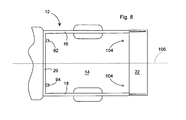
- FIG. 8 is a top view of the pickup truck of FIG. 1 with the bed extender removed to show the bores in the bed floor, and also showing the arms of the front support rack.
- FIGS. 1-4 illustrate a preferred embodiment of bed extender, generally 10 , mounted in pickup truck bed, generally 12 , and oriented to different positions.
- Bed 12 includes bed floor 14 , side walls 16 and 18 , front wall 20 , and tailgate 22 hinged at its lower edge to the rear edge of bed floor 14 .
- Tailgate 22 is moveable between a lowered horizontal position as illustrated in FIGS. 1 and 3 , and a raised, vertical position as illustrated in FIGS. 2 and 4 .
- Bed extender 10 is comprised of spaced, parallel, telescoping extension arms 30 and 32 , Crossbar 34 slidably inserted into crossbar connectors 36 and 38 attached to the outer ends of arms 30 and 32 , respectively, and hinge assemblies 40 and 42 pivotally attaching the inner ends of arms 30 and 32 , respectively, to pickup truck bed floor 14 .
- Arm 30 is comprised of an inner section 44 slidable within an outer section 46
- arm 32 is comprised of an inner section 48 slidable within an outer section 50
- Sections 46 and 50 include locking holes 52 selectively engaging spring loaded locking buttons 54 on inner sections 44 and 48 to secure arms 30 and 32 at the desired extensions.
- Crossbar connectors 36 and 38 in the illustrated embodiment are comprised of square tubular sections welded to the ends of arms 30 and 32 , respectively, transverse to the longitudinal centerline of truck bed 12 .
- Connectors 36 and 38 include horizontal bores having an outer diameter corresponding to the outer diameter of cross bar 34 , so that crossbar 34 is slidable within the bores.
- Hinge assemblies 40 and 42 are each comprised of a yoke 60 having spaced ears 62 with aligned bores 64 , and an eyebolt, generally 70 .
- eyebolt 70 is comprised of an upper bolt section 72 and a lower anchor section 74 .
- Bolt section includes an eye 76 and a threaded shank 78
- anchor section includes a shoulder 80 , and a threaded shank 82 with an internal threaded bore to receiving shank 78 .
- Nut 84 is threaded on the end of shank 82 .
- a coupling pin or bolt 86 couples eyebolt 70 to yoke 60 .
- hinge assemblies 40 and 42 are mounted at or adjacent the rear of bed floor 14 , whereby extender 10 will rest horizontally against bed floor 14 when in the forward orientation and horizontally against tailgate 22 when in the rearward orientation with tailgate 22 is in its lowered position.
- bed extender 10 may also include tailgate brackets 88 to releasably attach arms 30 and 32 to the inner wall of tailgate 22 , providing greater stability. Brackets 88 can also be used to hold bed extender 10 in the vertical position as shown in FIG. 4 .
- the exact configuration of brackets 88 is not critical, so long as the brackets secure extender 10 and are readily removable when uninstalling extender 10 .
- An optional, vertical support rack, generally 90 can be mounted at front wall 20 , as illustrated in FIGS. 4 and 8 , to support elongated items above truck bed 12 .
- Support rack 90 is comprised of spaced vertical telescoping arms 92 and 94 , having horizontal support rack crossbar 96 attached to the upper ends of arms 92 and 94 .
- Bed extender 10 may also include rectangular cover plate 100 , sized for attachment to arms 30 and 32 when extender 10 is in the rearward horizontal position.
- Plate may be of metal or wood, e.g., plywood or MDF. Plate may be attached with bolts or other suitable means, not shown.
- Pickup bed 12 is prepared for installation of bed extender 10 by first drilling a pair of spaced bores 104 in floor 14 adjacent the rear edge of floor 14 and equidistant on either side of an imaginary longitudinal centerline 106 as illustrated in FIG. 8 .
- Shanks 82 of eyebolts 70 are then inserted through bores 104 and bolted in place with nuts 84 as shown in FIG. 6 .
- Yokes 60 are then placed with yoke ears 62 on either side of eyebolt 70 and bolt 80 is inserted through ear bores 64 and eye 76 to pivotally attach the inner ends of arms 30 and 30 to floor 14 .
- crossbar 34 is slid through crossbar connectors 36 and 38 .
- extender 10 In use, with tailgate 22 in its lowered, horizontal position, extender 10 is pivoted rearwardly to the horizontal position as illustrated in FIG. 1 . In this position, elongated articles, e.g., lumber, can be placed in bed 14 with the rear of the articles extending beyond the rear of bed 14 , so that the rear of the articles rest on and are supported by crossbar 34 . When not in use, extender 10 can be pivoted through an 180° arc to rest on inside pickup bed 12 on floor 14 between side walls 16 and 18 .
- elongated articles e.g., lumber
Landscapes
- Engineering & Computer Science (AREA)
- Mechanical Engineering (AREA)
- Transportation (AREA)
- Chemical & Material Sciences (AREA)
- Combustion & Propulsion (AREA)
- Health & Medical Sciences (AREA)
- Public Health (AREA)
- Body Structure For Vehicles (AREA)
Abstract
A truck bed extender is described for use with a pickup truck having a bed with a bed floor, opposed side walls along each side of the bed floor and a tailgate hinged at the rear of the bed floor. Spaced, parallel, telescoping arms are pivotally attached at their inner ends to hinge assemblies secured to the floor of the bed adjacent the rear of the bed. A horizontal crossbar providing support for elongated articles is attached to the outer ends of the arms with crossbar connectors. Each hinge assembly includes an eyebolt with a shank inserted into a bore in the bed floor and a yoke attached to the inner end of an arm, with the ears of the yoke attached by a coupling bolt or pin that extends through bores in the yoke ears and the eye of the eyebolt.
Description
This application is a Continuation-in-Part of U.S. patent application Ser. No. 12/660,622, filed Mar. 2, 2010, which is incorporated herein by reference in its entirety.
1) Field of the Invention
The present invention relates to an apparatus for providing a greater load-bearing surface for a pickup truck bed, and in particular to a pickup truck bed extender that can be quickly attached and removed from a pickup truck bed, and pivoted inside the bed to rest on the bed floor when not in use.
2) Description of the Prior Art
The beds of most pickup trucks are shorter than many items, such as lumber, plywood, ladders, canoes, and other length items that the user needs to transport. As a result, the item extends beyond the back of the pickup truck bed, even with the tailgate in its lowered, horizontal position. Many items extend so far beyond the back of the bed that there is a risk of the item tipping and falling from the bed. In addition, many items require support near the rear end to prevent breakage.
This problem has been long recognized and numerous designs of devices known as truck bed extenders have been proposed. Generally, a conventional truck bed extender is comprised of a lower frame section or base that is attached, e.g., by bolting, to the pickup bed floor, and an upper frame section that is slidably attached to the lower frame section in a manner permitting rearward movement of the upper frame section beyond the rear of the pickup bed, thereby providing a carrying surface of greater length.
These conventional truck bed extenders, while somewhat useful for their designed function, have several disadvantages. Most bed extenders are designed for permanent installation in the truck bed, or are so difficult to remove that they are normally left in the truck bed. When not used as bed extenders, these devices take up a significant percentage of the carrying space available in the truck bed, diminishing the pickup truck's utility.
Pickup truck beds are available in a variety of widths. Many existing truck bed extenders are designed for use with a truck bed of a given dimension. As a result, it is not possible to move the bed extender to a truck bed of a different size. Commercially, manufacture and inventorying of bed extenders of different sizes is required to meet the requirements of different purchasers.
Therefore, there is a continuing need for a pickup truck bed extender that can be quickly installed in and removed from a pickup truck bed. There is also a need for a pickup truck bed that can be easily adjusted to fit different size pickup truck beds.
Generally, deficiencies of prior art truck bed extenders, including the above deficiencies, are addressed by the present invention, designed for quick and easy installation and removal from a pickup truck bed. As used herein, a pickup truck bed includes a bed floor with front and rear ends and parallel sides; opposed, parallel, vertical side walls attached at the sides of the bed floor; a vertical front wall attached at the front end of the bed floor; and a tail gate having a bottom edge hinged at the rear end of the bed floor. The tail gate is moveable between a closed, vertical orientation, and an open, horizontal orientation.
Unlike prior art bed extenders, the present bed extender is attached with hinge assemblies that are secured to the bed floor adjacent the junctures of the walls and bed floor and adjacent the rear of the bed floor. Generally, the present bed extender includes first and second parallel, telescoping extension arms, each arm having an inner end and an outer end; hinge assemblies pivotally attaching the inner ends of the extension arms to the bed floor, the hinge assemblies including shanks inserting into floor bores; and a crossbar attached to the outer ends of the extension arms, wherein the bed extender is pivotal between a rearward horizontal orientation against the tailgate and extending beyond the tailgate when the tailgate is in its lowered position and a forward horizontal orientation against the bed floor.
Each telescoping arm includes an outer tubular section and in inner section slidable within the outer section. The inner section may have an inner end attached to a hinge assembly, while the outer section has an outer end adapted for connection to the crossbar. However, it will be understood that the sections may be reversed, with the outer section having an inner end attached to a hinge assembly. The outer ends of the telescoping extension arms preferably include crossbar connectors for insertion of an end of the crossbar.
The hinge assemblies are designed for easy attachment of the extension arms, and for easy detachment of the extension arms when the extender is not in use. Generally, each hinge assembly is comprised of an eyebolt having an eye and a shank insertable into a floor bore, a yoke attachable to the inner end of an extension arm having spaced yoke ears with aligned bores positionable on either side of the eyebolt, and a latching pin or bolt (both being generally referred to as pins) insertable through the ear bores and the eyebolt eye to pivotally couple the yoke to the eyebolt. The yoke may, for example, be a Y-shaped yoke including a rearwardly extending shank that is inserted into a bore in the inner end of the telescoping arm.
The telescoping arms include locking means to secure the arm sections together at a desired extension. For example, one section may include one or more holes, while the other telescoping sections also include one or more mating holes, with holes in the two sections being selectively alignable for insertion of a pin or other locking means through the aligned holes to secure the sections together at a desired extension.
The outer ends of the telescoping arms include transverse crossbar connectors with horizontal openings sized to receive the crossbar. The crossbar and connectors also include locking means to secure the crossbar to the connectors. For example, alignable holes in the crossbar and connectors may be included for insertion of a pin or other locking member. The locking member may be permanently attached to one of the crossbar and spring loaded for easy assembly. Preferably, the connector is a transverse tubular arm attached to outer end of the telescoping arm, with the transverse arm having an opening sized to receive the crossbar. For example, a section of square tubing may be welded to the outer end of each arm, with the tubing having an inner diameter sized to receive the crossbar. Preferably, the arms and crossbar are constructed of square tubular metal, e.g., steel or aluminum.
To mount the bed extender in a pickup truck bed, two bores are first drilled at the desired locations in the bed. The bores are aligned transverse to the longitudinal centerline of the truck bed, i.e., a line drawn between the bores will be transverse to the centerline. The bores are preferably drilled equidistant from the centerline so that the extender will be centered on the truck bed.
A shank forming a part of each hinge assembly is inserted into each of the bores and secured in place. For example, if the shank is threaded, a nut can be attached to the shank beneath the truck bed. The telescoping arms and crossbar may be easily detached when not in use.
In a preferred embodiment, each hinge assembly includes an eyebolt with a shank insertable into a pickup bed bore, and a yoke attachable to the inner end of a telescoping arm. The eyebolt and yoke are pivotally coupled by inserting a pin, which may be a threaded bolt, through holes in the yoke ears and the eyebolt eye. The pins are simply removed to detach the arms and crossbar. Generally, the eyebolts will be left in place, since normal use of the truck bed is not affected by the eyebolts, which only extend above the bed by 1 or 2 inches. Alternatively, the extender can simply be rotated into the truck bed for storage. The eyebolt may also be designed with an eye portion that can be detached from the shank when the bed extender is removed from the truck bed.
Note also that the present bed extender is independent of the width of the truck bed. The differences in bed width are taken into account by location of the bed holes, with the crossbar being adjustable within the connectors for different spacing of the arms.
When used to support long items, the bed extender is used in a horizontal position with the tailgate in its lowered, horizontal position, so that the bed extender rests on, and extends rearwardly beyond, the tailgate. If desired, the apparatus can also include releasable attachment brackets to secure the bed extender to the tailgate.
The bed extender can also be used in a vertical orientation with the tailgate closed. In this position, longer items can extend at an upward angle from the front of the truck bed and rest on the horizontal crossbar instead of extending horizontally from the rear of the bed. In this orientation, the extender can also be used to support the rear of ladders and other long items with the front of the item being supported by a front support, which may be a rack on top of the truck cab, or a separate support rack attached to the front wall of the pickup truck bed. The bed extender can also be pivoted forward to a horizontal position where it rests on the bed floor.
The bed extender can also include a cover plate, such as a rectangular metal or wooden plate, attachable to the upper surfaces of the telescoping arms to enable carrying of smaller items. The plate can also be used as a work surface.
In the following description, terms such as horizontal, upright, vertical, above, below, beneath, and the like, are used solely for the purpose of clarity in illustrating the invention, and should not be taken as words of limitation. The drawings are for the purpose of illustrating the invention and are not intended to be to scale.
To minimize interference with other uses of the truck bed, to maximize the extension of bed extender 10, and to provide a bed extender 10 that is oriented horizontally when tailgate 22 is in the lowered position, hinge assemblies 40 and 42 are mounted at or adjacent the rear of bed floor 14, whereby extender 10 will rest horizontally against bed floor 14 when in the forward orientation and horizontally against tailgate 22 when in the rearward orientation with tailgate 22 is in its lowered position.
Optionally, bed extender 10 may also include tailgate brackets 88 to releasably attach arms 30 and 32 to the inner wall of tailgate 22, providing greater stability. Brackets 88 can also be used to hold bed extender 10 in the vertical position as shown in FIG. 4 . The exact configuration of brackets 88 is not critical, so long as the brackets secure extender 10 and are readily removable when uninstalling extender 10.
An optional, vertical support rack, generally 90, can be mounted at front wall 20, as illustrated in FIGS. 4 and 8 , to support elongated items above truck bed 12. Support rack 90 is comprised of spaced vertical telescoping arms 92 and 94, having horizontal support rack crossbar 96 attached to the upper ends of arms 92 and 94.
In use, with tailgate 22 in its lowered, horizontal position, extender 10 is pivoted rearwardly to the horizontal position as illustrated in FIG. 1 . In this position, elongated articles, e.g., lumber, can be placed in bed 14 with the rear of the articles extending beyond the rear of bed 14, so that the rear of the articles rest on and are supported by crossbar 34. When not in use, extender 10 can be pivoted through an 180° arc to rest on inside pickup bed 12 on floor 14 between side walls 16 and 18.
Certain modifications and improvements will occur to those skilled in the art upon a reading of the foregoing description. It should be understood that all such modifications and improvements have been deleted herein for the sake of conciseness and readability but are properly within the scope of the following claims.
Claims (12)
1. A truck bed extender for use with a pickup truck having a bed with a longitudinal centerline, a bed floor with spaced floor bores equidistant from said centerline and aligned transverse to said centerline, a vertical front wall at the front of the bed floor, opposed side walls along each side of the bed floor, and a tailgate having a raised vertical position and a lowered horizontal position hinged at the rear of the bed floor comprising:
a) first and second telescoping extension arms, each arm having an inner end and an outer end with a crossbar connector;
b) hinge assemblies pivotally attaching the inner ends of said extension arms to said bed floor, said hinge assemblies including an eyebolt having an eye and a shank insertable into a floor bore, a yoke attached to the inner end of an extension arm and spaced yoke ears with aligned bores positionable on either side of said eyebolt, and a latching pin or bolt insertable through said ear bores and said eyebolt eye; and
c) a crossbar attached to the said crossbar connectors, wherein said bed extender is pivotal between a rearward horizontal orientation against said tailgate when said tailgate is in its lowered position and a forward horizontal orientation against said bed floor, said extender extending rearwardly beyond the tailgate when in the rearward horizontal orientation.
2. The truck bed extender of claim 1 , wherein each of said telescoping arms includes an outer tubular section and in an inner section slidable within said outer tubular section.
3. The truck bed extender of claim 1 , further including tailgate hinge assemblies attachable to the inner side of said tailgate and to said extension arms.
4. The truck bed extender of claim 1 , further including a platform attachable to said extension arms.
5. The truck bed extender of claim 1 , wherein said hinge assemblies are adjacent the tailgate of said truck bed.
6. The truck bed extender of claim 1 , further including locking means to secure said crossbar to said arms.
7. A pickup truck and a truck bed extender combination comprising:
a) a pickup truck having a bed with a longitudinal centerline, a bed floor with spaced floor bores equidistant from said centerline and aligned transverse to said centerline, a vertical front wall at the front of the bed floor, opposed side walls along each side of the bed floor, and a tailgate having a raised vertical position and a lowered horizontal position hinged at the rear of the bed floor; and
b) the truck bed extender including first and second telescoping extension arms, each arm having an inner end and an outer end with a crossbar connector, hinge assemblies pivotally attaching the inner ends of said extension arms to said bed floor, said hinge assemblies including an eyebolt having an eye and a shank insertable into a floor bore, a yoke attached to the inner end of an extension mm and spaced yoke ears with aligned bores positionable on either side of said eyebolt, and a latching pin or bolt insertable through said ear bores and said eyebolt eye; and a crossbar attached to the said crossbar connectors, wherein said bed extender is pivotal between a rearward horizontal orientation against said tailgate when said tailgate is in its lowered position and a forward horizontal orientation against said bed floor, said extender extending rearwardly beyond the tailgate when in the rearward horizontal orientation.
8. The pickup truck and truck bed extender combination of claim 7 , wherein each of said telescoping arms includes an outer tubular section and an inner section slidable within said outer tubular section.
9. The pickup truck and truck bed extender combination of claim 7 , further including tailgate hinge assemblies attachable to the inner side of said tailgate and to said extension arms.
10. The pickup truck and truck bed extender combination of claim 7 , further including a platform attachable to said extension arms.
11. The pickup truck and truck bed extender combination of claim 7 , wherein said hinge assemblies are adjacent the tailgate of said truck bed.
12. The pickup truck and truck bed extender combination of claim 7 , further including locking means to secure said crossbar to said arms.
Priority Applications (1)
| Application Number | Priority Date | Filing Date | Title |
|---|---|---|---|
| US12/928,922 US8087709B2 (en) | 2010-03-02 | 2010-12-22 | Pickup truck bed extender |
Applications Claiming Priority (2)
| Application Number | Priority Date | Filing Date | Title |
|---|---|---|---|
| US12/660,622 US20110215608A1 (en) | 2010-03-02 | 2010-03-02 | Pickup truck bed extender |
| US12/928,922 US8087709B2 (en) | 2010-03-02 | 2010-12-22 | Pickup truck bed extender |
Related Parent Applications (1)
| Application Number | Title | Priority Date | Filing Date |
|---|---|---|---|
| US12/660,622 Continuation-In-Part US20110215608A1 (en) | 2010-03-02 | 2010-03-02 | Pickup truck bed extender |
Publications (2)
| Publication Number | Publication Date |
|---|---|
| US20110215609A1 US20110215609A1 (en) | 2011-09-08 |
| US8087709B2 true US8087709B2 (en) | 2012-01-03 |
Family
ID=44530687
Family Applications (1)
| Application Number | Title | Priority Date | Filing Date |
|---|---|---|---|
| US12/928,922 Expired - Fee Related US8087709B2 (en) | 2010-03-02 | 2010-12-22 | Pickup truck bed extender |
Country Status (1)
| Country | Link |
|---|---|
| US (1) | US8087709B2 (en) |
Cited By (5)
| Publication number | Priority date | Publication date | Assignee | Title |
|---|---|---|---|---|
| US20130094930A1 (en) * | 2011-10-12 | 2013-04-18 | Ford Global Technologies, Llc | Cargo box extension assembly for vehicle |
| US20190255987A1 (en) * | 2018-02-21 | 2019-08-22 | Kyle Neighbors | Vehicle tailgate having extension assembly |
| US20190329712A1 (en) * | 2018-01-30 | 2019-10-31 | Brad Damon Howell | Extendable Roof/ Truck Bed Racks |
| US11148598B1 (en) * | 2017-02-14 | 2021-10-19 | Francis Eman-Henshaw | Truck bed extension system and method of use |
| US20220161710A1 (en) * | 2020-11-24 | 2022-05-26 | Roger Don Alexander | Lockable Cargo Retaining Apparatus |
Families Citing this family (2)
| Publication number | Priority date | Publication date | Assignee | Title |
|---|---|---|---|---|
| CN103010317B (en) * | 2012-11-27 | 2016-06-08 | 曾德元 | Foldable type truck compartment |
| KR102774391B1 (en) * | 2024-08-01 | 2025-02-27 | (주)송한이엔지 | The slide bar for goods _oading and un_oading of the truck |
Citations (47)
| Publication number | Priority date | Publication date | Assignee | Title |
|---|---|---|---|---|
| US2727707A (en) * | 1952-08-22 | 1955-12-20 | Paul D Wells | Fishing outrigger |
| US3205108A (en) * | 1962-05-17 | 1965-09-07 | Nat Castings Co | Method and apparatus for making wound tubular articles of varying cross-section |
| US3589576A (en) * | 1969-11-04 | 1971-06-29 | James L Rinkle | Convertible rack for vehicle |
| US3765713A (en) * | 1972-03-30 | 1973-10-16 | L Suitt | Carrier rack for pick up trucks |
| US4023850A (en) * | 1975-04-02 | 1977-05-17 | Tillery James M | Tailgate extension |
| US4057281A (en) * | 1976-04-07 | 1977-11-08 | Garrett Luther J | Carrying rack for trucks |
| US4138046A (en) * | 1975-04-04 | 1979-02-06 | Freze William E De | Demountable truck bed load-supporting rack |
| US4211448A (en) * | 1977-10-26 | 1980-07-08 | Weston Robert M | Adjustable rack assembly |
| US4267948A (en) * | 1979-06-11 | 1981-05-19 | Lewis David W | Cargo carrier |
| US4770458A (en) * | 1987-04-16 | 1988-09-13 | William S. Tokarsky | Utility rack for pickup truck |
| US4953757A (en) * | 1989-06-14 | 1990-09-04 | Stevens James R | Front rack for a truck |
| US5037152A (en) * | 1990-10-26 | 1991-08-06 | Pwhh, Inc. | Collapsible truck rack |
| US5143415A (en) * | 1991-05-31 | 1992-09-01 | Jemb Rack Systems, Inc. | Disassemblable, lightweight truck utility rack |
| US5190337A (en) * | 1991-09-24 | 1993-03-02 | Columbia Mfg., Inc. | Collapsible pipe rack for pickup trucks |
| US5192107A (en) * | 1990-02-21 | 1993-03-09 | Smith Sr Delbert L | Telescopic truck rack |
| US5522685A (en) * | 1994-11-28 | 1996-06-04 | Lessard; Jean-Luc P. | Snowmobile transport aid |
| US5564773A (en) * | 1994-12-15 | 1996-10-15 | Stahl/Scott Fetzer Company | Pickup truck bed cover |
| US5628540A (en) * | 1995-10-23 | 1997-05-13 | James; William L. | Pickup truck utility rack |
| US5662254A (en) * | 1995-08-16 | 1997-09-02 | Kar-Rite International | Rack for vehicles |
| US5700047A (en) * | 1996-05-21 | 1997-12-23 | Horst Leitner | Truck bed extender |
| US5743702A (en) * | 1996-05-03 | 1998-04-28 | Gunderson; Michael J. | Method and apparatus for a vehicle mounted hoisting system |
| US5836635A (en) * | 1996-05-31 | 1998-11-17 | Dorman; John R. | Knockdown truck rack apparatus and method |
| US5911464A (en) * | 1997-10-30 | 1999-06-15 | White; Keith Richard | Auxiliary tailgate |
| US5944371A (en) * | 1996-11-18 | 1999-08-31 | Magna Eybl Ges.M.B.H. | Load panel for the luggage area of a motor vehicle |
| US6089795A (en) * | 1997-10-03 | 2000-07-18 | Booth; Larry | Mobile apparatus for pneumatic conveyance of gravel or similar granular material |
| US6233874B1 (en) * | 2000-01-06 | 2001-05-22 | Marvin B. Johnson, Jr. | Free-standing safety gate |
| US6257637B1 (en) * | 1999-10-15 | 2001-07-10 | Wendal T. Reed | Removable tailgate extender net |
| US6402215B1 (en) * | 1996-05-21 | 2002-06-11 | American Moto Products, Inc. | Vehicle cargo bed extender |
| US6425618B1 (en) * | 2001-07-19 | 2002-07-30 | Ford Global Technologies, Inc. | Articulating cargo bed extender |
| US6698810B1 (en) * | 2002-09-23 | 2004-03-02 | David A. M. Lane | Telescoping, multifunction tailgate extender |
| US6719345B2 (en) * | 2001-12-26 | 2004-04-13 | Fuji Jukogyo Kabushiki Kaisha | Structure for extending bed of pickup truck |
| US6746066B2 (en) * | 2000-02-22 | 2004-06-08 | Harry F. Reed | Truck bed extension |
| US20040134953A1 (en) * | 2003-01-09 | 2004-07-15 | Perez Carlos Valadez | Multi positionable rack for a pick up truck bed |
| US20050077747A1 (en) * | 2002-07-24 | 2005-04-14 | Webasto Vehicle Systems International Gmbh | Frame element for mounting in the lower area of the back window of a motor vehicle and a vehicle with one such element |
| US6948763B2 (en) * | 2003-02-11 | 2005-09-27 | Timothy Robbins | Cover assembly for truck bed extender |
| US6991277B1 (en) * | 2005-02-09 | 2006-01-31 | Toyota Technical Center Usa, Inc. | Integrated multi-function tailgate |
| US7100956B1 (en) * | 2005-06-27 | 2006-09-05 | Wilkins Paul T | Tire carrier apparatus |
| US7195432B2 (en) * | 2005-04-21 | 2007-03-27 | Stephen Earle | Adjustable cargo gate system |
| US7241093B2 (en) * | 2004-04-26 | 2007-07-10 | Francisco Zuniga | Cargo securing device |
| US7296836B1 (en) * | 2004-06-07 | 2007-11-20 | Zeljko Sabo | Truck rack apparatus |
| US20080111390A1 (en) * | 2006-10-27 | 2008-05-15 | Anthony Smith | Vehicle cargo tailgate enclosure |
| US7464976B2 (en) * | 2005-10-28 | 2008-12-16 | 89908, Inc. | Vehicle bed storage rack and bed divider |
| US7473269B1 (en) * | 2001-03-16 | 2009-01-06 | Warsaw Orthopedic, Inc. | Spinal fixation system and related methods |
| US20090108612A1 (en) * | 2007-10-29 | 2009-04-30 | Anthony Smith | Vehicle tailgate enclosure with enhanced adjustment |
| US7533921B2 (en) * | 2007-07-27 | 2009-05-19 | Richard Ferrell | Multifunctional extendable tailgate |
| US7641251B1 (en) * | 2007-06-29 | 2010-01-05 | Goorgen Stepanians | Collapsible truck rack and method of use |
| US7665799B1 (en) * | 2006-09-15 | 2010-02-23 | Appropriate Combined Technologies, Llc | Truck bed extension and roll bar apparatus |
-
2010
- 2010-12-22 US US12/928,922 patent/US8087709B2/en not_active Expired - Fee Related
Patent Citations (52)
| Publication number | Priority date | Publication date | Assignee | Title |
|---|---|---|---|---|
| US2727707A (en) * | 1952-08-22 | 1955-12-20 | Paul D Wells | Fishing outrigger |
| US3205108A (en) * | 1962-05-17 | 1965-09-07 | Nat Castings Co | Method and apparatus for making wound tubular articles of varying cross-section |
| US3589576A (en) * | 1969-11-04 | 1971-06-29 | James L Rinkle | Convertible rack for vehicle |
| US3765713A (en) * | 1972-03-30 | 1973-10-16 | L Suitt | Carrier rack for pick up trucks |
| US4023850A (en) * | 1975-04-02 | 1977-05-17 | Tillery James M | Tailgate extension |
| US4138046A (en) * | 1975-04-04 | 1979-02-06 | Freze William E De | Demountable truck bed load-supporting rack |
| US4057281A (en) * | 1976-04-07 | 1977-11-08 | Garrett Luther J | Carrying rack for trucks |
| US4211448A (en) * | 1977-10-26 | 1980-07-08 | Weston Robert M | Adjustable rack assembly |
| US4267948A (en) * | 1979-06-11 | 1981-05-19 | Lewis David W | Cargo carrier |
| US4770458A (en) * | 1987-04-16 | 1988-09-13 | William S. Tokarsky | Utility rack for pickup truck |
| US4953757A (en) * | 1989-06-14 | 1990-09-04 | Stevens James R | Front rack for a truck |
| US5192107A (en) * | 1990-02-21 | 1993-03-09 | Smith Sr Delbert L | Telescopic truck rack |
| US5037152A (en) * | 1990-10-26 | 1991-08-06 | Pwhh, Inc. | Collapsible truck rack |
| US5143415A (en) * | 1991-05-31 | 1992-09-01 | Jemb Rack Systems, Inc. | Disassemblable, lightweight truck utility rack |
| US5190337A (en) * | 1991-09-24 | 1993-03-02 | Columbia Mfg., Inc. | Collapsible pipe rack for pickup trucks |
| US5522685A (en) * | 1994-11-28 | 1996-06-04 | Lessard; Jean-Luc P. | Snowmobile transport aid |
| US5564773A (en) * | 1994-12-15 | 1996-10-15 | Stahl/Scott Fetzer Company | Pickup truck bed cover |
| US5662254A (en) * | 1995-08-16 | 1997-09-02 | Kar-Rite International | Rack for vehicles |
| US5628540A (en) * | 1995-10-23 | 1997-05-13 | James; William L. | Pickup truck utility rack |
| US5743702A (en) * | 1996-05-03 | 1998-04-28 | Gunderson; Michael J. | Method and apparatus for a vehicle mounted hoisting system |
| US5700047A (en) * | 1996-05-21 | 1997-12-23 | Horst Leitner | Truck bed extender |
| US6113173A (en) * | 1996-05-21 | 2000-09-05 | American Moto Products, Inc. | Truck bed extender |
| US7654598B2 (en) * | 1996-05-21 | 2010-02-02 | 89908, Inc. | Vehicle cargo bed extender |
| US6805392B2 (en) * | 1996-05-21 | 2004-10-19 | American Moto Products, Inc. | Vehicle cargo bed extender |
| US6402215B1 (en) * | 1996-05-21 | 2002-06-11 | American Moto Products, Inc. | Vehicle cargo bed extender |
| US7063366B2 (en) * | 1996-05-21 | 2006-06-20 | 89908, Inc | Vehicle cargo bed extender |
| US5836635A (en) * | 1996-05-31 | 1998-11-17 | Dorman; John R. | Knockdown truck rack apparatus and method |
| US5944371A (en) * | 1996-11-18 | 1999-08-31 | Magna Eybl Ges.M.B.H. | Load panel for the luggage area of a motor vehicle |
| US6089795A (en) * | 1997-10-03 | 2000-07-18 | Booth; Larry | Mobile apparatus for pneumatic conveyance of gravel or similar granular material |
| US5911464A (en) * | 1997-10-30 | 1999-06-15 | White; Keith Richard | Auxiliary tailgate |
| US6257637B1 (en) * | 1999-10-15 | 2001-07-10 | Wendal T. Reed | Removable tailgate extender net |
| US6233874B1 (en) * | 2000-01-06 | 2001-05-22 | Marvin B. Johnson, Jr. | Free-standing safety gate |
| US6746066B2 (en) * | 2000-02-22 | 2004-06-08 | Harry F. Reed | Truck bed extension |
| US7473269B1 (en) * | 2001-03-16 | 2009-01-06 | Warsaw Orthopedic, Inc. | Spinal fixation system and related methods |
| US6425618B1 (en) * | 2001-07-19 | 2002-07-30 | Ford Global Technologies, Inc. | Articulating cargo bed extender |
| US6719345B2 (en) * | 2001-12-26 | 2004-04-13 | Fuji Jukogyo Kabushiki Kaisha | Structure for extending bed of pickup truck |
| US20050077747A1 (en) * | 2002-07-24 | 2005-04-14 | Webasto Vehicle Systems International Gmbh | Frame element for mounting in the lower area of the back window of a motor vehicle and a vehicle with one such element |
| US6698810B1 (en) * | 2002-09-23 | 2004-03-02 | David A. M. Lane | Telescoping, multifunction tailgate extender |
| US20040134953A1 (en) * | 2003-01-09 | 2004-07-15 | Perez Carlos Valadez | Multi positionable rack for a pick up truck bed |
| US6948763B2 (en) * | 2003-02-11 | 2005-09-27 | Timothy Robbins | Cover assembly for truck bed extender |
| US7241093B2 (en) * | 2004-04-26 | 2007-07-10 | Francisco Zuniga | Cargo securing device |
| US7296836B1 (en) * | 2004-06-07 | 2007-11-20 | Zeljko Sabo | Truck rack apparatus |
| US6991277B1 (en) * | 2005-02-09 | 2006-01-31 | Toyota Technical Center Usa, Inc. | Integrated multi-function tailgate |
| US7195432B2 (en) * | 2005-04-21 | 2007-03-27 | Stephen Earle | Adjustable cargo gate system |
| US7303222B2 (en) * | 2005-06-27 | 2007-12-04 | Wilkins Paul T | Tire carrier apparatus |
| US7100956B1 (en) * | 2005-06-27 | 2006-09-05 | Wilkins Paul T | Tire carrier apparatus |
| US7464976B2 (en) * | 2005-10-28 | 2008-12-16 | 89908, Inc. | Vehicle bed storage rack and bed divider |
| US7665799B1 (en) * | 2006-09-15 | 2010-02-23 | Appropriate Combined Technologies, Llc | Truck bed extension and roll bar apparatus |
| US20080111390A1 (en) * | 2006-10-27 | 2008-05-15 | Anthony Smith | Vehicle cargo tailgate enclosure |
| US7641251B1 (en) * | 2007-06-29 | 2010-01-05 | Goorgen Stepanians | Collapsible truck rack and method of use |
| US7533921B2 (en) * | 2007-07-27 | 2009-05-19 | Richard Ferrell | Multifunctional extendable tailgate |
| US20090108612A1 (en) * | 2007-10-29 | 2009-04-30 | Anthony Smith | Vehicle tailgate enclosure with enhanced adjustment |
Cited By (7)
| Publication number | Priority date | Publication date | Assignee | Title |
|---|---|---|---|---|
| US20130094930A1 (en) * | 2011-10-12 | 2013-04-18 | Ford Global Technologies, Llc | Cargo box extension assembly for vehicle |
| US8857880B2 (en) * | 2011-10-12 | 2014-10-14 | Ford Global Technologies, Llc | Cargo box extension assembly for vehicle |
| US11148598B1 (en) * | 2017-02-14 | 2021-10-19 | Francis Eman-Henshaw | Truck bed extension system and method of use |
| US20190329712A1 (en) * | 2018-01-30 | 2019-10-31 | Brad Damon Howell | Extendable Roof/ Truck Bed Racks |
| US20190255987A1 (en) * | 2018-02-21 | 2019-08-22 | Kyle Neighbors | Vehicle tailgate having extension assembly |
| US10525870B2 (en) * | 2018-02-21 | 2020-01-07 | Fca Us Llc | Vehicle tailgate having extension assembly |
| US20220161710A1 (en) * | 2020-11-24 | 2022-05-26 | Roger Don Alexander | Lockable Cargo Retaining Apparatus |
Also Published As
| Publication number | Publication date |
|---|---|
| US20110215609A1 (en) | 2011-09-08 |
Similar Documents
| Publication | Publication Date | Title |
|---|---|---|
| US8087709B2 (en) | Pickup truck bed extender | |
| US11260796B2 (en) | Detachable workpiece support apparatus for a tailgate step | |
| US8714594B1 (en) | Combine header transport trailer | |
| US6609481B1 (en) | Game animal lift assembly for all terrain vehicles | |
| US20100290876A1 (en) | Cargo Lift For All Terrain Vehicle | |
| US10358073B2 (en) | Truck loader | |
| US8882436B2 (en) | ATV ramp | |
| CA2153029A1 (en) | Truck bed extender | |
| US7740430B2 (en) | Support assembly for use with truck bed | |
| US9845117B2 (en) | Adjustable support structure for vehicle cargo bed extension | |
| US8070028B2 (en) | Foldable truck bed extender | |
| US20060022477A1 (en) | Multipurpose trailer system | |
| US9546082B2 (en) | Fork truck boom apparatus | |
| US20180257721A1 (en) | Foldable utility trailer | |
| US3995594A (en) | Combination hay handler and feeder | |
| US20110215608A1 (en) | Pickup truck bed extender | |
| US9889786B1 (en) | Pivotal loading apparatus for a tailgate | |
| US7540689B1 (en) | Counterweight system | |
| US7669809B1 (en) | Saddle lift apparatus | |
| US8985660B1 (en) | Apparatus and method for accessing the bed of a pickup truck | |
| US20060104767A1 (en) | Game rack for an all terrain vehicle | |
| US6213530B1 (en) | Truck bed extender | |
| US8740249B1 (en) | Combine header transport trailer | |
| CA2707527C (en) | A mounting kit | |
| US20010015564A1 (en) | Truck bed extender |
Legal Events
| Date | Code | Title | Description |
|---|---|---|---|
| STCF | Information on status: patent grant |
Free format text: PATENTED CASE |
|
| FPAY | Fee payment |
Year of fee payment: 4 |
|
| FEPP | Fee payment procedure |
Free format text: MAINTENANCE FEE REMINDER MAILED (ORIGINAL EVENT CODE: REM.); ENTITY STATUS OF PATENT OWNER: SMALL ENTITY |
|
| LAPS | Lapse for failure to pay maintenance fees |
Free format text: PATENT EXPIRED FOR FAILURE TO PAY MAINTENANCE FEES (ORIGINAL EVENT CODE: EXP.); ENTITY STATUS OF PATENT OWNER: SMALL ENTITY |
|
| STCH | Information on status: patent discontinuation |
Free format text: PATENT EXPIRED DUE TO NONPAYMENT OF MAINTENANCE FEES UNDER 37 CFR 1.362 |
|
| FP | Lapsed due to failure to pay maintenance fee |
Effective date: 20200103 |