US8086877B2 - Storage device and control method for the same - Google Patents
Storage device and control method for the same Download PDFInfo
- Publication number
- US8086877B2 US8086877B2 US12/232,218 US23221808A US8086877B2 US 8086877 B2 US8086877 B2 US 8086877B2 US 23221808 A US23221808 A US 23221808A US 8086877 B2 US8086877 B2 US 8086877B2
- Authority
- US
- United States
- Prior art keywords
- pool
- capacity
- management
- raid group
- pools
- Prior art date
- Legal status (The legal status is an assumption and is not a legal conclusion. Google has not performed a legal analysis and makes no representation as to the accuracy of the status listed.)
- Expired - Fee Related, expires
Links
- 238000000034 method Methods 0.000 title claims description 77
- 238000005457 optimization Methods 0.000 claims description 9
- 238000003491 array Methods 0.000 claims description 2
- 238000012544 monitoring process Methods 0.000 claims 2
- 238000010586 diagram Methods 0.000 description 24
- 238000011946 reduction process Methods 0.000 description 13
- 238000012423 maintenance Methods 0.000 description 8
- 238000012217 deletion Methods 0.000 description 5
- 230000037430 deletion Effects 0.000 description 5
- 230000004044 response Effects 0.000 description 5
- 238000005516 engineering process Methods 0.000 description 2
- 230000000694 effects Effects 0.000 description 1
- 239000000835 fiber Substances 0.000 description 1
Images


Classifications
-
- G—PHYSICS
- G06—COMPUTING; CALCULATING OR COUNTING
- G06F—ELECTRIC DIGITAL DATA PROCESSING
- G06F3/00—Input arrangements for transferring data to be processed into a form capable of being handled by the computer; Output arrangements for transferring data from processing unit to output unit, e.g. interface arrangements
- G06F3/06—Digital input from, or digital output to, record carriers, e.g. RAID, emulated record carriers or networked record carriers
- G06F3/0601—Interfaces specially adapted for storage systems
- G06F3/0602—Interfaces specially adapted for storage systems specifically adapted to achieve a particular effect
- G06F3/0625—Power saving in storage systems
-
- G—PHYSICS
- G06—COMPUTING; CALCULATING OR COUNTING
- G06F—ELECTRIC DIGITAL DATA PROCESSING
- G06F1/00—Details not covered by groups G06F3/00 - G06F13/00 and G06F21/00
- G06F1/26—Power supply means, e.g. regulation thereof
- G06F1/32—Means for saving power
- G06F1/3203—Power management, i.e. event-based initiation of a power-saving mode
- G06F1/3206—Monitoring of events, devices or parameters that trigger a change in power modality
- G06F1/3215—Monitoring of peripheral devices
- G06F1/3221—Monitoring of peripheral devices of disk drive devices
-
- G—PHYSICS
- G06—COMPUTING; CALCULATING OR COUNTING
- G06F—ELECTRIC DIGITAL DATA PROCESSING
- G06F1/00—Details not covered by groups G06F3/00 - G06F13/00 and G06F21/00
- G06F1/26—Power supply means, e.g. regulation thereof
- G06F1/32—Means for saving power
- G06F1/3203—Power management, i.e. event-based initiation of a power-saving mode
- G06F1/3234—Power saving characterised by the action undertaken
- G06F1/325—Power saving in peripheral device
- G06F1/3268—Power saving in hard disk drive
-
- G—PHYSICS
- G06—COMPUTING; CALCULATING OR COUNTING
- G06F—ELECTRIC DIGITAL DATA PROCESSING
- G06F3/00—Input arrangements for transferring data to be processed into a form capable of being handled by the computer; Output arrangements for transferring data from processing unit to output unit, e.g. interface arrangements
- G06F3/06—Digital input from, or digital output to, record carriers, e.g. RAID, emulated record carriers or networked record carriers
- G06F3/0601—Interfaces specially adapted for storage systems
- G06F3/0628—Interfaces specially adapted for storage systems making use of a particular technique
- G06F3/0638—Organizing or formatting or addressing of data
- G06F3/0644—Management of space entities, e.g. partitions, extents, pools
-
- G—PHYSICS
- G06—COMPUTING; CALCULATING OR COUNTING
- G06F—ELECTRIC DIGITAL DATA PROCESSING
- G06F3/00—Input arrangements for transferring data to be processed into a form capable of being handled by the computer; Output arrangements for transferring data from processing unit to output unit, e.g. interface arrangements
- G06F3/06—Digital input from, or digital output to, record carriers, e.g. RAID, emulated record carriers or networked record carriers
- G06F3/0601—Interfaces specially adapted for storage systems
- G06F3/0628—Interfaces specially adapted for storage systems making use of a particular technique
- G06F3/0646—Horizontal data movement in storage systems, i.e. moving data in between storage devices or systems
- G06F3/0647—Migration mechanisms
- G06F3/0649—Lifecycle management
-
- G—PHYSICS
- G06—COMPUTING; CALCULATING OR COUNTING
- G06F—ELECTRIC DIGITAL DATA PROCESSING
- G06F3/00—Input arrangements for transferring data to be processed into a form capable of being handled by the computer; Output arrangements for transferring data from processing unit to output unit, e.g. interface arrangements
- G06F3/06—Digital input from, or digital output to, record carriers, e.g. RAID, emulated record carriers or networked record carriers
- G06F3/0601—Interfaces specially adapted for storage systems
- G06F3/0628—Interfaces specially adapted for storage systems making use of a particular technique
- G06F3/0662—Virtualisation aspects
- G06F3/0665—Virtualisation aspects at area level, e.g. provisioning of virtual or logical volumes
-
- G—PHYSICS
- G06—COMPUTING; CALCULATING OR COUNTING
- G06F—ELECTRIC DIGITAL DATA PROCESSING
- G06F3/00—Input arrangements for transferring data to be processed into a form capable of being handled by the computer; Output arrangements for transferring data from processing unit to output unit, e.g. interface arrangements
- G06F3/06—Digital input from, or digital output to, record carriers, e.g. RAID, emulated record carriers or networked record carriers
- G06F3/0601—Interfaces specially adapted for storage systems
- G06F3/0668—Interfaces specially adapted for storage systems adopting a particular infrastructure
- G06F3/0671—In-line storage system
- G06F3/0683—Plurality of storage devices
- G06F3/0689—Disk arrays, e.g. RAID, JBOD
-
- G—PHYSICS
- G11—INFORMATION STORAGE
- G11B—INFORMATION STORAGE BASED ON RELATIVE MOVEMENT BETWEEN RECORD CARRIER AND TRANSDUCER
- G11B19/00—Driving, starting, stopping record carriers not specifically of filamentary or web form, or of supports therefor; Control thereof; Control of operating function ; Driving both disc and head
- G11B19/20—Driving; Starting; Stopping; Control thereof
- G11B19/209—Driving; Starting; Stopping; Control thereof in multiple disk arrays, e.g. spindle synchronisation in RAID systems
-
- Y—GENERAL TAGGING OF NEW TECHNOLOGICAL DEVELOPMENTS; GENERAL TAGGING OF CROSS-SECTIONAL TECHNOLOGIES SPANNING OVER SEVERAL SECTIONS OF THE IPC; TECHNICAL SUBJECTS COVERED BY FORMER USPC CROSS-REFERENCE ART COLLECTIONS [XRACs] AND DIGESTS
- Y02—TECHNOLOGIES OR APPLICATIONS FOR MITIGATION OR ADAPTATION AGAINST CLIMATE CHANGE
- Y02D—CLIMATE CHANGE MITIGATION TECHNOLOGIES IN INFORMATION AND COMMUNICATION TECHNOLOGIES [ICT], I.E. INFORMATION AND COMMUNICATION TECHNOLOGIES AIMING AT THE REDUCTION OF THEIR OWN ENERGY USE
- Y02D10/00—Energy efficient computing, e.g. low power processors, power management or thermal management
-
- Y—GENERAL TAGGING OF NEW TECHNOLOGICAL DEVELOPMENTS; GENERAL TAGGING OF CROSS-SECTIONAL TECHNOLOGIES SPANNING OVER SEVERAL SECTIONS OF THE IPC; TECHNICAL SUBJECTS COVERED BY FORMER USPC CROSS-REFERENCE ART COLLECTIONS [XRACs] AND DIGESTS
- Y02—TECHNOLOGIES OR APPLICATIONS FOR MITIGATION OR ADAPTATION AGAINST CLIMATE CHANGE
- Y02D—CLIMATE CHANGE MITIGATION TECHNOLOGIES IN INFORMATION AND COMMUNICATION TECHNOLOGIES [ICT], I.E. INFORMATION AND COMMUNICATION TECHNOLOGIES AIMING AT THE REDUCTION OF THEIR OWN ENERGY USE
- Y02D30/00—Reducing energy consumption in communication networks
- Y02D30/50—Reducing energy consumption in communication networks in wire-line communication networks, e.g. low power modes or reduced link rate
Definitions
- the present invention relates to a storage device and a control method therefor and, more specifically, is suitable when it is applied to a storage device storing data utilizing virtual volumes, and a method for controlling such a storage device.
- virtual volumes consuming no physical storage area are defined, these virtual volumes are provided to a server, and allocation of the physical storage areas is performed at the time of actual data writing from the server, thereby increasing the use efficiency of the storage capacity of a storage device.
- any pools corresponding to virtual volumes are dynamically increased in storage capacity.
- a host computer monitors logical block address of a read or write I/O (Input/Output) for accessing logical volumes of a storage device, and based on any acquired logical block, the storage area of the logical volumes is dynamically extended.
- I/O Input/Output
- An example includes Patent Document 1 (JP-A-2003-15915).
- the power needed for storage resources allocated to pools is reduced, and the storage resources are prevented from being reduced in life.
- Patent Document 2 JP-A-2007-293442).
- a virtual volume is created to a storage area referred to as pool, which is configured by one or more pool volumes each being a hard disk drive.
- pool volumes are exemplified by disk drives configuring an RAID group (Redundant Arrays of Inexpensive Disks).
- RAID group Redundant Arrays of Inexpensive Disks
- Another problem here is that, once created, the storage capacity of a pool cannot be reduced even if the pool is found out as not carrying data that much for actual use during operation of a storage system.
- the use rate of the storage capacity of the pool reaches a predetermined threshold value, an operator is required to increase the storage capacity of the pool in consideration of the application of the pool and the characteristics of the pool volumes.
- the virtual volumes allocated thereto will not become available for use, thereby causing a need to monitor frequently the use rate of the storage capacity of the pool.
- the operator is required to select any of the pool volumes in the storage system for allocation to the pools with consideration given to the characteristics of the pool volumes such as capacity and performance, and add thus selected pool volumes respectively to the pools.
- the volume being a transfer destination is required to have the same capacity as the volume being a transfer source. This causes consumption of a physical storage area in any area that is vacant in the volume of transfer source.
- a physical storage area remains allocated to a page of the data, thereby consuming the physical storage area.
- the invention is proposed in consideration of such problems, and an object thereof is to provide a storage system that can achieve reduction of power consumption, simplification of management, and increase of use efficiency of storage resources, and a method for controlling such a storage device.
- An aspect of the invention is directed to a storage device that stores data from a host computer in one or more hard disk drives via a virtual volume.
- the storage device includes: a first management section that manages a storage area provided by the one or more hard disk drives on a basis of a predetermined unit created using one or more parameters; a second management section that manages, on a basis of a pool configured by at least one or more of the units under the management of the first management section, a management policy about the capacity of the pools and a threshold value of the storage capacity of the pools; a power supply control section that controls each of the hard disk drives of the unit under the management of the first management section to be in either a first turn-ON state or a second turn-ON state with a low power consumption; and a control section that selects, when the storage capacity of any of the pools exceeds the threshold value, the management policy of the pool, and any of the parameters considered optimum to serve as the unit of the storage area under the management of the first management section, and after making the power supply control section to
- FIG. 1 is a diagram showing the entire configuration of a storage system in a first embodiment of the invention
- FIG. 2 is a diagram showing a storage area management table of the first embodiment
- FIG. 3 is a diagram showing a RAID group management table of the first embodiment
- FIG. 4 is a diagram showing a pool management table of the first embodiment
- FIG. 5 is a diagram for illustrating a dynamic storage area allocation process of the first embodiment
- FIG. 6 is a diagram showing the relationship between a virtual storage area of a virtual volume and a physical storage area storing physical data of the first embodiment
- FIG. 7 is a flowchart of a process at the time of writing by a dynamic storage area allocation section of the first embodiment
- FIG. 8 is a flowchart of a process at the time of reading by the dynamic storage area allocation section of the first embodiment
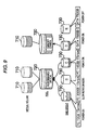
- FIG. 9 is a diagram for illustrating the relationship among virtual groups, pools, and RAID groups (pool volumes) of the first embodiment
- FIG. 10 is a diagram for illustrating a pool capacity increase process of the first embodiment
- FIG. 11 is a diagram for illustrating a pool capacity reduction process of the first embodiment
- FIG. 12 is a diagram for illustrating a zero data deletion process of the first embodiment
- FIG. 13 is a diagram for illustrating a release process of the first embodiment
- FIG. 14 is a flowchart of a RAID group new entry process of the first embodiment
- FIG. 15 is a flowchart of a pool setting process of the first embodiment
- FIG. 16 is a flowchart of the pool capacity increase process of the first embodiment
- FIG. 17 is a flowchart of the pool capacity reduction process and a pool capacity optimization process of the first embodiment.
- FIG. 18 is a diagram showing an exemplary screen display at the time of RAID group reduction in a second embodiment of the invention.
- FIG. 1 is a diagram showing the entire configuration of a storage system.
- a storage system 1 is configured to include a host computer 100 , a computer 110 , a maintenance terminal (SVP) 120 , and a storage device 200 .
- SVP maintenance terminal
- a connection is established over a network 130 .
- the maintenance terminal 120 is connected to the storage device 200 .
- the host computer 100 executes various operations by running an application program (not shown), and stores the result in the storage device 200 . That is, the host computer 100 writes data of operation results into the storage device 200 over the network 130 , and when necessary, reads thus written data from the storage device 200 .
- the computer 110 manages the storage device 200 connected to the network 130 .
- the maintenance terminal 120 is provided for maintenance use of the storage device 200 .
- the computer 110 and the maintenance terminal 120 are provided with storage management sections 111 and 121 , respectively.
- the storage management section may be provided to either the computer 110 or the maintenance terminal 120 in the storage system.
- the storage management sections 111 and 121 operate similarly to each other, and the details thereof are left for later description.
- the storage device 200 is configured to include an interface control section 210 , a memory 220 , a disk control section 230 , and a hard disk drive (HDD) 240 .
- the interface control section 210 controls data exchange between the host computer 100 and the computer 120 .
- the memory 220 includes areas for storage of various types of components and tables, i.e., a dynamic storage area allocation section 221 , a RAID group power supply control section 222 , a RAID group allocation section 223 , a storage area management table 300 , a RAID group management table 400 , and a pool management table 500 .
- the disk control section 230 controls over data writing to the hard disk drive 240 and data reading therefrom.
- the dynamic storage area allocation section 221 executes a process of dynamically allocating the storage areas.
- the RAID group power supply control section 222 performs power saving control on a RAID group basis.
- the RAID group allocation section 223 executes a process of allocating the RAID groups to the host computer 100 .
- the storage contents in the tables i.e., the storage area management table 300 , the RAID group management table 400 , and the pool management table 500 , will be described later.
- FIG. 2 is a diagram showing the storage area management table 300 .
- the storage area management table 300 carries information entered about physical storage areas for allocation to the host computer 100 .
- the storage area management table 300 includes a storage area number field 310 , a physical storage area allocation YES/NO field 320 , and a physical storage area ID field 330 .
- the storage area number field 310 stores numbers respectively assigned to the storage areas.
- the physical storage area allocation field 320 stores information about whether the host computer 100 is allocated with a physical storage area or not. When the host computer 100 is allocated with, as a physical storage area, the storage area identified by the storage area number, the physical storage area allocation field 320 stores “YES”, and when not allocated, the field 320 stores “NO”.
- the physical storage area ID field 330 stores IDs (Identifiers) of the physical storage areas.
- the storage area management table 300 various types of information is stored in a line, e.g., the storage area number field 310 stores “P7151”, the physical storage area allocation field 320 stores “YES”, and the physical storage area ID field 330 stores “Axxxx”.
- FIG. 3 is a diagram showing the RAID group management table 400 .
- the RAID group management table 400 manages the RAID groups.
- the RAID group management table 400 includes a number field 410 , a RAID level field 420 , a hard disk drive type field 430 , a hard disk drive capacity field 440 , a rotation frequency field 450 , a power supply state field 460 , a unused capacity field 470 , and an allocated pool number field 480 .
- the number field 410 stores numbers of the RAID groups.
- the RAID level field 420 stores information about RAID levels such as RAID 1.
- the hard disk drive type field 430 stores information about the type of the hard disk drive 240 , e.g., “FC (Fiber Channel)” and “SATA (Serial Advanced Technology Attachment)”.
- the hard disk drive capacity field 440 stores information about the capacity (GB: Giga Byte) of the hard disk drive 240 .
- the rotation frequency field 450 stores information about the rotation frequency of the hard disk drive 240 .
- the power supply state field 460 stores information indicating the state of a power supply, e.g., “ON”, “slow rotation mode”, and “OFF”. Herein, “ON” indicates the state that the power supply is normally turned ON.
- the free space field 470 stores information indicating the free spaces by specific values.
- the allocation pool number field 480 stores information indicating numbers of pools allocated with a physical storage area.
- the number field 410 stores “1”
- the RAID level field 420 stores “RAID1(2D+2D)”
- the hard disk drive type field 430 stores “FC”
- the hard disk drive capacity field 440 stores “73”
- the rotation frequency field 450 stores “15 krpm”
- the power supply state field 460 stores “ON”
- the free space field 470 stores “XXX (value indicating the free space)”
- the allocation pool number field 480 stores “1”.
- FIG. 4 is a diagram showing the pool management table 500 .
- the pool management table 500 is provided for management of pools provided from the storage areas of the hard disk drive 240 .
- the pool management table 500 includes a number field 510 , a threshold value field 520 , a total capacity field 530 , a policy field 540 , a free space field 550 , and an allocated RAID group field 560 .
- the number field 510 stores numbers of pools.
- the threshold value field 520 stores information about a threshold use rate of the storage capacity of each of the pools.
- the total capacity field 530 stores information about the capacity of each of the pools.
- the policy field 540 stores information about policies. These policies each indicate how to perform control over each of the RAID groups, and the details thereof are left for later description.
- the free space field 550 stores information indicating the free space.
- the allocated RAID group field 560 stores information about any allocated RAID group.
- the number field 510 stores “1”
- the threshold value field 520 stores “80”
- the total capacity field 530 stores “XXX”
- the policy field 540 stores “performance critical”
- the free space field 550 stores “yyy (value indicating the free space)”
- the allocated RAID group field 560 stores “1, 2”.
- policies to be stored in the policy field 540 There are four policies available for an operator to set, i.e., “performance critical”, “capacity critical”, “power saving critical”, and “reliability critical”.
- RAID group parameters are specified for use as determination criteria, i.e., parameters under the management of the RAID group management table 400 .
- determination criteria i.e., parameters under the management of the RAID group management table 400 .
- parameters are each assigned a priority to indicate which parameter is more critical.
- the priority precedence is: “hard disk type (FC or not)”, “rotation frequency (high or not), “capacity (large or not)”, and “RAID level (RAID1>6>5)”.
- the priority precedence is: “hard disk capacity (large or not)”, and “RAID level (RAID5>6>1, and a few number of hard disk drives?)”.
- the priority precedence is: “rotation frequency (low or not)”, “hard disk capacity (large or not)”, “RAID level (a few number of hard disk drives?), and “RAID level 5>6>1)”.
- the priority precedence is: “hard disk type (FC or not)”, and “RAID level (RAID1>6>5)”.
- the RAID group allocation section 223 selects any of the RAID groups considered most suitable for each of the policies. Such a selection is made based on the information stored in the power supply state field 460 of the RAID group management table 400 .
- the RAID group to be selected from those exemplified in the RAID group management table 400 is the RAID group #3 if with the policy of “performance critical”, the RAID group #9 if with the policy of “capacity critical”, the RAID group #8 if with the policy of “power saving critical”, and the RAID group #4 if with the policy of “reliability critical”. Note that these policies are surely not restrictive, and an operator may create his or her own policies by setting any arbitrary determination criteria, e.g., parameters and priority precedence.
- FIG. 5 is a diagram for illustrating such a dynamic storage area allocation process.
- FIG. 6 is a diagram showing the relationship between a virtual storage area of a virtual volume and a physical storage area for storage of physical data. Note that the dynamic storage area allocation process is sometimes referred to as HDP (Hitachi Dynamic Provisioning) or thin provisioning.
- HDP Hitachi Dynamic Provisioning
- the dynamic storage area allocation section 221 performs dynamic allocation of a physical storage area as shown in FIG. 6 .
- the data in storage is updated.
- “0” is forwarded to the host computer 100 as a response to indicate no physical storage area is allocated. Note that such write and read processes are executed using the storage area management table 300 described above.
- FIG. 7 is a flowchart of a process during writing of the dynamic storage area allocation section 221 .
- FIG. 8 is a flowchart of a process during reading of the dynamic storage area allocation section 221 .
- step S 101 the dynamic storage area allocation section 221 determines whether an area of write data specified by the host computer 100 is already allocated with a storage area or not.
- the procedure goes to step S 102 , and the dynamic storage area allocation section 221 performs allocation of a storage area, and then in step S 103 , updates the storage area management table 300 .
- step S 104 the dynamic storage area allocation section 221 stores the data in the memory 220 . This is the end of the write process. Note that the data stored in the memory 220 is then written into the hard disk drive 240 by the disk control section 230 .
- step S 201 the dynamic storage area allocation section 221 determines whether an area of read data specified by the host computer 100 is already allocated with a storage area or not.
- the procedure goes to step S 202 , in step S 202 , and the dynamic storage area allocation section 221 returns the stored data to the host computer 100 .
- the dynamic storage area allocation section 221 returns “0” to the host computer 100 . This is the end of the read process.
- pool capacity increase process and a pool capacity reduction process are to be executed by the RAID group allocation section 223 .
- FIG. 9 is a diagram for illustrating the relationship among virtual volumes, pools, and RAID groups (pool volumes).
- a pool is set corresponding to a virtual volume 710 .
- one pool 720 is associated with two virtual volumes, and another pool 720 is associated with one virtual volume.
- These pools 720 are each also associated with RAID group(s) corresponding to a policy set thereto.
- the pool 720 with a policy of “performance critical” is associated with RAID groups 730 A and 730 C
- the pool 720 with a policy of “capacity critical” is associated with a RAID group 730 D.
- a RAID group 730 B is in the “slow rotation” mode
- a RAID group 730 E is in the “OFF” state, i.e., both are in the state of power saving.
- FIG. 10 is a diagram for illustrating the pool capacity increase process.
- the pool 720 is provided with a storage area from the RAID group 730 A, and is set with a threshold value as described by referring to the pool management table 500 .
- the RAID group 730 in the “OFF” state or in the “slow rotation” mode is searched for any RAID group most suitable for the policy of the pool 720 , and using thus found RAID group, i.e., RAID group 730 X, the pool capacity is increased.
- the RAID group 730 X is put in the state of “ON”, and as shown in the lower portion of FIG. 10 , the pool 720 is now provided with a storage area each from the RAID groups 730 A and 730 X.
- the pool 720 is thus increased in capacity by the RAID group 730 X, and thus a new threshold value is set to the pool management table 500 .
- a process similar to the above process is to be executed. In this manner, the pool capacity increase process is automatically executed.
- FIG. 11 is a diagram for illustrating the pool capacity reduction process.
- the pool 720 is provided with a storage area from the RAID groups 730 A and 730 B.
- a search is made for any of the RAID groups 730 as a target for capacity reduction based on the policy of the pool 720 .
- the RAID groups 730 A and 730 B share the same priority based on the pool, when the RAID group 730 A stores data larger in amount than the RAID group 730 B, the RAID group 730 B is the target for capacity reduction.
- executed is a process of reducing the capacity of the pool 720 , and transferring the data stored in the RAID group 730 B to the RAID group 730 A.
- the RAID group 730 B is put in the “OFF” state or in the “slow rotation” mode, i.e., put in the state of power saving. In this manner, the pool capacity reduction process is automatically executed.
- FIG. 12 is a diagram for illustrating this zero data deletion process.
- zero data is deleted (2 in FIG. 12 ).
- This zero data is the one written when data transfer is taken place from the normal volume (RAID group) 730 to the virtual volume 710 (1 in FIG. 12 ).
- This zero data is deleted by deleting any page being entirely “0”.
- the page here is a unit for management of data of a hard disk drive. With such data deletion, any extra data allocated to a physical storage area can be deleted, thereby being able to increase the efficiency of the storage capacity of the pool 720 .
- the RAID group being the transfer source is added to the RAID group of shared use, and the resulting RAID group is put in the “OFF” state or in the “slow rotation” mode (3 in FIG. 12 ). In this manner, the RAID group being the transfer source can be used again as the capacity of the pool, thereby being able to increase the use efficiency of the physical storage area and achieve power saving.
- the host computer 100 issues a command for deleting the data in the virtual volume 710 , and a command for the disk control section 230 to release any area in the virtual volume 710 allocated with data (left portion of FIG. 13 ).
- the disk control section 230 releases the area in the virtual volume 710 allocated with the data (center portion of FIG. 13 ).
- the unused area in the virtual volume 710 is increased (right portion of FIG. 13 ).
- SCSI Small Computer Systems Interface
- step S 102 the RAID group allocation section 223 acquires information about any RAID groups not yet used in the storage device 200 , and then forwards thus acquired information to the storage management section 111 .
- step S 103 the storage management section 111 receives the information about the RAID groups not yet used in the storage device 200 .
- the storage management section 111 selects any one specific not-yet-used RAID group from the acquired information.
- step S 105 the storage management section 111 forwards, to the RAID group allocation section 223 , a command for entering thus selected RAID group into the RAID group management table 400 .
- step S 106 the RAID group allocation section 223 enters, into the RAID group management table 400 , the selected RAID group provided in step S 105 .
- step S 107 the RAID group allocation section 223 reads the pool management table 500 and the RAID group management table 400 , and then in step S 108 , a determination is made whether or not there is any pool closest, in terms of policy, to the RAID group entered as such.
- the reason for setting the RAID groups differently as such is as follows. That is, there may be a case where the RAID group to be entered may be closest, in terms of policy, to any of the pools in the pool management table 500 . If this is the case, because it is highly possible that the RAID group to be entered is an immediate target for capacity increase, the RAID group is put in the “slow rotation” mode with which the capacity addition to the pool can be completed in a shorter time. On the other hand, when the RAID group being a capacity reduction target does not match any of the pool policies, it means that the RAID group may not be put in operation for a while so that the power is turned OFF.
- step S 111 the RAID group allocation section 223 updates the RAID group management table 400 , and notifies as such to the storage management section 111 .
- step S 112 the storage management section 111 notifies the operator of completion of RAID group entry. This is the end of the RAID group new entry process.
- FIG. 15 is a flowchart of a pool setting process.
- the pool setting process a pool newly set with a policy is created, and the resulting pool is allocated with any of the RAID groups in the RAID group management table 400 .
- the pool setting process is executed by the storage management section 111 and the RAID group allocation section 223 .
- the storage management section 121 may surely execute the process as an alternative to the storage management section 111 .
- step S 201 the storage management section 111 issues a command to the RAID group allocation section 223 for creating a new pool.
- step S 202 the RAID group allocation section 223 reads the RAID group management table 400 . Then in step S 203 , the RAID group allocation section 223 determines whether the RAID group management table 400 carries therein any RAID group in the “OFF” state or in the “slow rotation” mode.
- step S 204 the RAID group allocation section 223 determines whether or not there is any RAID group not found in the RAID management table 400 but is acknowledged.
- step S 205 the RAID group allocation section 223 forwards information of alert to the storage management section 111 .
- step S 206 the storage management section 111 displays, for the operator, an alert message telling that no pool can be created because there is no RAID group.
- step S 207 the RAID group allocation section 223 executes the RAID group new entry process. This enables acknowledging of, as a RAID group, any hard disk drive disposed and acknowledged in the storage device 200 but is not entered as a RAID group.
- step S 208 in response to a command coming from the operator, the storage management section 111 sets the pool with a policy.
- step S 209 in response to a command coming from the operator, the storage management section 111 sets the pool with a threshold value. Such information is forwarded to the RAID group allocation section 223 .
- step S 210 based on the policy, the RAID group allocation section 223 selects any of the RAID groups from the RAID group management table 400 .
- step S 211 the RAID group allocation section 223 adds thus selected RAID group to the pool capacity.
- step S 212 the RAID group allocation section 223 updates the pool management table 500 and the RAID group management table 400 .
- step S 213 the storage management section 111 completes the pool setting.
- FIG. 16 is a flowchart of the pool capacity increase process.
- a pool is set, and while the pool set as such is being used, the pool capacity is increased in units of a RAID group in accordance with the policy set to the pool.
- This pool capacity increase process is to be executed by the RAID group allocation section 223 .
- the RAID group allocation section 223 determines in step S 301 whether a predetermined time has been passed or not. When the determination result tells not yet (S 301 : NO), the procedure goes to step S 302 . In step S 302 , the RAID group allocation section 223 then determines whether a pool capacity increase command is provided or not. When the determination result tells not yet (S 302 : NO), the procedure returns to step S 301 . That is, the RAID group allocation section 223 monitors the lapse of a predetermined time, and whether a pool capacity increase command is provided or not.
- the predetermined time may be a preset time interval, or a time designated by the operator.
- step S 303 the RAID group allocation section 223 reads the pool management table 500 .
- step S 304 the RAID group allocation section 223 checks the use rate of the pool capacity.
- step S 305 the RAID group allocation section 223 reads the RAID group management table.
- step S 306 the RAID group allocation section 223 determines whether the use rate of the pool capacity has reached the threshold value or not.
- step S 307 the RAID group allocation section 223 determines whether there is any RAID group in the “OFF” state or in the “slow rotation” mode. When there is no such RAID group (S 307 : NO), in step S 313 , the RAID group allocation section 223 issues an alert message to the storage management section 111 . In this manner, the operator can be notified that the pool capacity cannot be automatically increased.
- step S 308 the RAID group allocation section 223 determines whether or not such a RAID group is plurally found.
- step S 309 from the RAID groups in the “OFF” state or in the “slow rotation” mode, the RAID group allocation section 223 selects, based on the policy set to the pool, any of the RAID group closest in terms of policy.
- step S 310 the RAID group allocation section 223 puts the RAID group in the ready state. That is, when being in the “OFF” state, the RAID group is turned ON, and when being in the “slow rotation” mode, the RAID group is rotated faster.
- FIG. 17 is a flowchart of the pool capacity reduction process and a pool capacity optimization process.
- a pool is set, and while the pool set as such is being used, the pool capacity is reduced in units of a RAID group in accordance with the policy set to the pool.
- the pool optimization process any area in the pool that has been allocated to the virtual volume but is not yet used is released, thereby increasing the free space in the pool. Thereafter, when the capacity of the pool satisfies requirements for capacity reduction, the capacity is accordingly reduced.
- These processes i.e., the pool capacity reduction process and the pool capacity optimization process, are both executed by the RAID group allocation section 223 .
- the RAID group allocation section 223 determines in step S 401 whether a predetermined time has been passed or not. When the determination result tells not yet (S 401 : NO), the procedure goes to step S 402 . In step S 402 , the RAID group allocation section 223 then determines whether a pool optimization command is provided or not. When the determination result tells not yet (S 402 : NO), the procedure returns to step S 401 . That is, the RAID group allocation section 223 monitors the lapse of a predetermined time, and whether a pool optimization command is provided or not.
- the predetermined time may be a preset time interval, or a time designated by the operator.
- step S 403 the RAID group allocation section 223 determines whether or not the pool is allocated with a plurality of RAID groups. When the pool is not allocated with a plurality of RAID groups (S 403 : NO), this is the end of the process.
- step S 404 When the pool is allocated with a plurality of RAID groups (S 403 : YES), or when the pool optimization command is received (S 402 : YES) and when the RAID group allocation section 223 releases any area in step S 404 , i.e., any area in the pool that has been allocated to the virtual volume but is not yet used, the procedure goes to step S 405 .
- step S 405 the RAID group allocation section 223 reads the pool management table 500 .
- step S 406 the RAID group allocation section 223 checks the use rate of the capacity of the pool.
- step S 407 the RAID group allocation section 223 reads the RAID group management table.
- step S 408 the RAID group allocation section 223 determines whether the use rate satisfies the requirements for capacity reduction or not. When the requirements are not satisfied (S 408 : NO), the procedure returns to step S 401 .
- Pt denotes the entire capacity of a pool
- Pc denotes the entire amount of use of the pool
- Rt denotes the capacity of a RAID group with the lowest priority
- a denotes the free space at the time of capacity reduction (arbitrary value).
- step S 409 the RAID group allocation section 223 moves, based on the policy, the data of the RAID group with the lowest priority to the free space of any other RAID group.
- step S 410 the RAID group allocation section 223 releases the RAID group from the pool.
- step S 411 the RAID group allocation section 223 determines whether or not there is any pool closest, in terms of policy, to the RAID group being the capacity reduction target.
- step S 412 the RAID group allocation section 223 sets the RAID group in the “slow rotation” mode.
- step S 413 the procedure goes to step S 413 , and the RAID group allocation section 223 sets the RAID group in the “OFF” state.
- the reason for setting the RAID groups differently as such is the same as that described above in step S 108 , and thus is not described twice.
- step S 414 the RAID group allocation section 223 updates the pool management table 500 and the RAID group management table 400 . This is the end of the process.
- the storage system 1 can implement reduction of power consumption, simplification of management, and increase of use efficiency of storage resources.
- the storage system 1 also can perform electrical control in units of a RAID group in accordance with the application of a pool and the capacity use rate thereof. Moreover, because the RAID management table 400 is shared among a plurality of pools 720 , the spare storage capacity that has been required to be ready for every pool can be shared among the pools 720 , thereby being able to use the capacity with good efficiency.
- the storage system 1 automatically selects any RAID group considered appropriate based on the policy from the RAID group management table 400 , i.e., RAID group 730 , and the capacity of the pools 720 is increased by turning ON the virtual volume or increasing the rotation speed thereof. This favorably saves the trouble of an operator to frequently monitor the capacity use rate, and to increase the capacity manually.
- the storage system 1 automatically selects any RAID group considered appropriate based on the policy of the pool 720 from the RAID group management table 400 , i.e., RAID group 730 , and the data in the RAID group 730 is entirely moved to any other RAID group 730 in the same pool 720 .
- the storage system 1 then turns OFF the selected RAID group 730 or put it in the “slow rotation” mode, and enters the RAID group 730 again in the RAID group management table 400 .
- the hard disk drive 240 can be increased in capacity use rate and in electrical efficiency with respect to the capacity of the hard disk drive 240 in use can be increased.
- the storage system 1 also deletes the zero data of the virtual volume 710 that has been written at the time of data transfer from the virtual volume 710 , and deletes any extra data having been allocated as a physical storage area.
- the storage system 1 then performs data transfer to the virtual volume 710 , thereby enabling the efficient use of the capacity to be increased.
- the RAID group 730 being the transfer source is added to the RAID group management table 400 of the pool 720 , and then is turned OFF or is put into the “slow rotation” mode to be ready for the next use as the capacity of the pool 720 . In this manner, the physical storage area can be increased in use efficiency and power saving can be achieved.
- the storage system 1 releases any area to which the data has been allocated in the virtual volume 710 , thereby increasing the free space.
- Exemplified in the first embodiment is the case that the pool reduction process is executed automatically.
- an operator may be notified of any RAID group to be reduced, and the reduction process may be executed in response to a command issued by the operator.
- FIG. 18 is a diagram showing an exemplary screen display of a pool management screen at the time of RAID group reduction.
- This screen display 600 is to be displayed at the time of the RAID group reduction process that will be described later.
- This pool management screen may be displayed on the computer 110 , or on the maintenance terminal 120 .
- the screen display 600 includes a table 600 and a detailed information area 610 .
- the table 600 displays potential RAID group(s) to be reduced, and the detailed information area 610 displays the detailed information of the RAID group(s).
- the table 600 includes a designation field 611 , a RAID group number field 612 , an LU number field 613 , a pool number field 614 , a reduction YES/NO field 615 , a power saving YES/NO field 616 , and a scroll bar field 617 .
- the designation field 611 designates any of the RAID groups for display of detailed information on the detailed information area 610 .
- the RAID group number field 612 displays the number(s) of the RAID group(s) to be reduced.
- the RAID group number(s) displayed here is a list of any RAID groups that are under the management of the RAID group management table 400 , and are being turned ON.
- the LU number field 613 displays LU numbers of the LUs configuring the RAID group.
- the pool number field 614 displays the numbers of the pools.
- the reduction YES/NO field 615 displays whether the RAID group can be reduced or not, i.e., the determination of YES/NO is made based on whether the RAID group or the LU is satisfying the requirements for pool capacity reduction or not.
- the power saving YES/NO field 818 displays whether the RAID group can be put in the state of power saving or not. Assuming that in a RAID group, a plurality of LUs are placed across a plurality of pools, when every LU can be reduced from the pool, the RAID group can be put in the state of power saving.
- the scroll bar field 617 displays the RAID group(s) not displayed on the table 610 by scrolling the screen.
- the detailed information area 620 displays the detailed information of the RAID group designated by the designation field 611 .
- the detailed information display 621 of the detailed information includes, specifically, the entire capacity, the amount of use, the RAID level, and the HDD type.
- the detailed information area 620 displays reduction buttons 622 and 623 .
- the reduction button 622 is provided for issuing a command for turning OFF the RAID group after capacity reduction of the pool.
- the reduction button 623 is provided for issuing a command for putting the RAID group into the “slow rotation” mode after capacity reduction from the pool.
- a display is made to indicate their power saving effect.
- an operator can save power by referring to the display screen 600 at the time of RAID group reduction process.
- the storage device 200 is exemplified as including: the RAID group management table 400 that manages storage areas provided by one or more hard disk drives 240 on the basis of a RAID group created using one or more parameters; the pool management table 500 that manages, for every hard disk drive 240 of a pool configured by at least one or more RAID groups under the management of the RAID group management table 400 , a policy related to the capacity of the pool and a threshold value of the storage capacity of the pool; the RAID group power supply control section 222 that performs control on a RAID group basis, i.e., any RAID group 730 used in the pool is put in a turn-ON state, and any RAID group 730 not used in the pool is put in a turn-OFF state or in a slow rotation mode for power saving; and the RAID group allocation section 223 that selects, when the
- the invention can be widely applied to the storage device and the control method thereof.
Landscapes
- Engineering & Computer Science (AREA)
- Theoretical Computer Science (AREA)
- Physics & Mathematics (AREA)
- General Engineering & Computer Science (AREA)
- General Physics & Mathematics (AREA)
- Human Computer Interaction (AREA)
- Power Sources (AREA)
Abstract
Description
Threshold Value (%)>Pc/(Pt−Rt)×100+α (1)
Claims (12)
Applications Claiming Priority (2)
| Application Number | Priority Date | Filing Date | Title |
|---|---|---|---|
| JP2008-193724 | 2008-07-28 | ||
| JP2008193724A JP2010033261A (en) | 2008-07-28 | 2008-07-28 | Storage device and control method |
Publications (2)
| Publication Number | Publication Date |
|---|---|
| US20100023685A1 US20100023685A1 (en) | 2010-01-28 |
| US8086877B2 true US8086877B2 (en) | 2011-12-27 |
Family
ID=41569647
Family Applications (1)
| Application Number | Title | Priority Date | Filing Date |
|---|---|---|---|
| US12/232,218 Expired - Fee Related US8086877B2 (en) | 2008-07-28 | 2008-09-12 | Storage device and control method for the same |
Country Status (2)
| Country | Link |
|---|---|
| US (1) | US8086877B2 (en) |
| JP (1) | JP2010033261A (en) |
Cited By (2)
| Publication number | Priority date | Publication date | Assignee | Title |
|---|---|---|---|---|
| US20110252212A1 (en) * | 2004-04-09 | 2011-10-13 | Hitachi, Ltd. | Storage control system and method |
| US20140122799A1 (en) * | 2012-10-26 | 2014-05-01 | Inventec Corporation | Storage device and power saving method thereof |
Families Citing this family (27)
| Publication number | Priority date | Publication date | Assignee | Title |
|---|---|---|---|---|
| US8583893B2 (en) | 2009-05-28 | 2013-11-12 | Marvell World Trade Ltd. | Metadata management for virtual volumes |
| US8793290B1 (en) * | 2010-02-24 | 2014-07-29 | Toshiba Corporation | Metadata management for pools of storage disks |
| WO2011135617A1 (en) * | 2010-04-27 | 2011-11-03 | 株式会社日立製作所 | Method and storage device for limiting total capacity of virtual volumes associated with pool |
| JP5451875B2 (en) * | 2010-04-30 | 2014-03-26 | 株式会社日立製作所 | Computer system and storage control method thereof |
| CN102754084B (en) * | 2010-05-18 | 2015-10-07 | 株式会社日立制作所 | Memory storage and data managing method |
| WO2012011153A1 (en) * | 2010-07-22 | 2012-01-26 | Hitachi, Ltd. | Data storage apparatus and data storage control method for the same |
| JP5427314B2 (en) * | 2010-08-26 | 2014-02-26 | 株式会社日立製作所 | Storage system providing virtual volume and power saving control method of the storage system |
| US9411517B2 (en) * | 2010-08-30 | 2016-08-09 | Vmware, Inc. | System software interfaces for space-optimized block devices |
| US20120096059A1 (en) * | 2010-10-13 | 2012-04-19 | Hitachi, Ltd. | Storage apparatus and file system management method |
| US8825950B2 (en) * | 2011-03-01 | 2014-09-02 | Lsi Corporation | Redundant array of inexpensive disks (RAID) system configured to reduce rebuild time and to prevent data sprawl |
| US9128910B1 (en) * | 2011-03-16 | 2015-09-08 | Tintri Inc. | Avoiding long access latencies in redundant storage systems |
| WO2013076974A1 (en) * | 2011-11-24 | 2013-05-30 | パナソニック株式会社 | Drive device |
| US9047201B2 (en) * | 2011-12-25 | 2015-06-02 | Synology Incorporated | Method for waking up a plurality of hibernated mass storage devices |
| JP5857849B2 (en) | 2012-03-30 | 2016-02-10 | 富士通株式会社 | Storage device, activation device determination method, and program |
| US9870152B2 (en) * | 2012-06-07 | 2018-01-16 | Hitachi, Ltd. | Management system and management method for managing data units constituting schemas of a database |
| JP2014010655A (en) * | 2012-06-29 | 2014-01-20 | Fujitsu Ltd | Control device, control method, and control program |
| US9135176B1 (en) * | 2012-06-30 | 2015-09-15 | Emc Corporation | System and method for thin provisioning |
| WO2014087497A1 (en) * | 2012-12-05 | 2014-06-12 | 株式会社日立製作所 | Storage device and control method therfor |
| WO2014115320A1 (en) * | 2013-01-25 | 2014-07-31 | 株式会社日立製作所 | Storage system and data management method |
| US20160004476A1 (en) * | 2013-07-03 | 2016-01-07 | Hitachi, Ltd. | Thin provisioning of virtual storage system |
| US9727255B2 (en) * | 2013-07-19 | 2017-08-08 | Hitachi, Ltd. | Storage apparatus and storage control method |
| US9990263B1 (en) * | 2015-03-20 | 2018-06-05 | Tintri Inc. | Efficient use of spare device(s) associated with a group of devices |
| JP6569477B2 (en) * | 2015-11-02 | 2019-09-04 | 富士通株式会社 | Storage control device and control program |
| KR102664665B1 (en) * | 2016-08-22 | 2024-05-16 | 에스케이하이닉스 주식회사 | Memory system |
| WO2018116392A1 (en) * | 2016-12-21 | 2018-06-28 | 株式会社日立製作所 | Information processing system and information processing method |
| CN109213618B (en) * | 2017-06-30 | 2022-04-12 | 伊姆西Ip控股有限责任公司 | Method, apparatus and computer program product for managing a storage system |
| US11481134B1 (en) * | 2021-05-24 | 2022-10-25 | Sap Se | Adaptive caching for hybrid columnar databases with heterogeneous page sizes |
Citations (7)
| Publication number | Priority date | Publication date | Assignee | Title |
|---|---|---|---|---|
| JP2003015915A (en) | 2001-07-05 | 2003-01-17 | Hitachi Ltd | Automatic expansion method for storage device capacity |
| US20070079099A1 (en) * | 2005-10-04 | 2007-04-05 | Hitachi, Ltd. | Data management method in storage pool and virtual volume in DKC |
| US20070250679A1 (en) * | 2006-04-21 | 2007-10-25 | Shoko Umemura | Storage system and method for controlling the same |
| US20080229048A1 (en) * | 2007-03-14 | 2008-09-18 | Atsushi Murase | Method and apparatus for chunk allocation in a thin provisioning storage system |
| US20090083558A1 (en) * | 2007-09-26 | 2009-03-26 | Hitachi, Ltd. | Storage apparatus and power saving method thereof |
| US20090119529A1 (en) * | 2007-11-02 | 2009-05-07 | Hitachi Ltd. | Configuration optimization method for a storage system |
| US20090276588A1 (en) * | 2008-04-30 | 2009-11-05 | Atsushi Murase | Free space utilization in tiered storage systems |
-
2008
- 2008-07-28 JP JP2008193724A patent/JP2010033261A/en active Pending
- 2008-09-12 US US12/232,218 patent/US8086877B2/en not_active Expired - Fee Related
Patent Citations (9)
| Publication number | Priority date | Publication date | Assignee | Title |
|---|---|---|---|---|
| JP2003015915A (en) | 2001-07-05 | 2003-01-17 | Hitachi Ltd | Automatic expansion method for storage device capacity |
| US20050091455A1 (en) | 2001-07-05 | 2005-04-28 | Yoshiki Kano | Automated on-line capacity expansion method for storage device |
| US20070079099A1 (en) * | 2005-10-04 | 2007-04-05 | Hitachi, Ltd. | Data management method in storage pool and virtual volume in DKC |
| US20070250679A1 (en) * | 2006-04-21 | 2007-10-25 | Shoko Umemura | Storage system and method for controlling the same |
| JP2007293442A (en) | 2006-04-21 | 2007-11-08 | Hitachi Ltd | Storage system and its control method |
| US20080229048A1 (en) * | 2007-03-14 | 2008-09-18 | Atsushi Murase | Method and apparatus for chunk allocation in a thin provisioning storage system |
| US20090083558A1 (en) * | 2007-09-26 | 2009-03-26 | Hitachi, Ltd. | Storage apparatus and power saving method thereof |
| US20090119529A1 (en) * | 2007-11-02 | 2009-05-07 | Hitachi Ltd. | Configuration optimization method for a storage system |
| US20090276588A1 (en) * | 2008-04-30 | 2009-11-05 | Atsushi Murase | Free space utilization in tiered storage systems |
Non-Patent Citations (2)
| Title |
|---|
| Dell Systems-"Getting Started With RAID"; 16 pages, Dated Feb. 2003. * |
| Dell Systems—"Getting Started With RAID"; 16 pages, Dated Feb. 2003. * |
Cited By (3)
| Publication number | Priority date | Publication date | Assignee | Title |
|---|---|---|---|---|
| US20110252212A1 (en) * | 2004-04-09 | 2011-10-13 | Hitachi, Ltd. | Storage control system and method |
| US8433686B2 (en) * | 2004-04-09 | 2013-04-30 | Hitachi, Ltd. | Storage control system and method |
| US20140122799A1 (en) * | 2012-10-26 | 2014-05-01 | Inventec Corporation | Storage device and power saving method thereof |
Also Published As
| Publication number | Publication date |
|---|---|
| US20100023685A1 (en) | 2010-01-28 |
| JP2010033261A (en) | 2010-02-12 |
Similar Documents
| Publication | Publication Date | Title |
|---|---|---|
| US8086877B2 (en) | Storage device and control method for the same | |
| US7613896B2 (en) | Storage area dynamic assignment method | |
| US8527702B2 (en) | Storage system providing virtual volumes | |
| US8261036B2 (en) | Storage system comprising function for reducing power consumption | |
| JP4819369B2 (en) | Storage system | |
| US8024603B2 (en) | Data migration satisfying migration-destination requirements | |
| US7587553B2 (en) | Storage controller, and logical volume formation method for the storage controller | |
| JP4684864B2 (en) | Storage device system and storage control method | |
| JP4885575B2 (en) | Storage area allocation optimization method and management computer for realizing the method | |
| US20070250679A1 (en) | Storage system and method for controlling the same | |
| WO2010095176A1 (en) | Storage system and method for operating storage system | |
| US20100082900A1 (en) | Management device for storage device | |
| US8296543B2 (en) | Computer system management apparatus and management method for the computer system | |
| JP2007066259A (en) | Computer system, storage system and volume capacity expansion method | |
| JP2009301525A (en) | Storage device using flash memory | |
| JP2010073095A (en) | Computer system and control method therefor | |
| JP2008070935A (en) | Logical volume management method and logical volume management program for storage system, and storage system | |
| JP2010072753A (en) | Storage system equipped with automatic extension volume and power saving function | |
| JP5130169B2 (en) | Method for allocating physical volume area to virtualized volume and storage device | |
| JP2008234056A (en) | Storage device and control method for cache residence in storage system | |
| US7529900B2 (en) | Computer system and storage system and volume assignment method | |
| JP2008299559A (en) | Storage system and data transfer method for storage system | |
| US8555004B2 (en) | Storage system having function of performing formatting or shredding | |
| JP2000222285A (en) | Memory power managing device |
Legal Events
| Date | Code | Title | Description |
|---|---|---|---|
| AS | Assignment |
Owner name: HITACHI, LTD., JAPAN Free format text: ASSIGNMENT OF ASSIGNORS INTEREST;ASSIGNORS:IKEJIRI, KEITARO;INNAN, MASATAKA;TABUCHI, HIDEO;REEL/FRAME:021591/0256 Effective date: 20080901 |
|
| ZAAA | Notice of allowance and fees due |
Free format text: ORIGINAL CODE: NOA |
|
| ZAAB | Notice of allowance mailed |
Free format text: ORIGINAL CODE: MN/=. |
|
| FEPP | Fee payment procedure |
Free format text: PAYER NUMBER DE-ASSIGNED (ORIGINAL EVENT CODE: RMPN); ENTITY STATUS OF PATENT OWNER: LARGE ENTITY Free format text: PAYOR NUMBER ASSIGNED (ORIGINAL EVENT CODE: ASPN); ENTITY STATUS OF PATENT OWNER: LARGE ENTITY |
|
| STCF | Information on status: patent grant |
Free format text: PATENTED CASE |
|
| FPAY | Fee payment |
Year of fee payment: 4 |
|
| MAFP | Maintenance fee payment |
Free format text: PAYMENT OF MAINTENANCE FEE, 8TH YEAR, LARGE ENTITY (ORIGINAL EVENT CODE: M1552); ENTITY STATUS OF PATENT OWNER: LARGE ENTITY Year of fee payment: 8 |
|
| FEPP | Fee payment procedure |
Free format text: MAINTENANCE FEE REMINDER MAILED (ORIGINAL EVENT CODE: REM.); ENTITY STATUS OF PATENT OWNER: LARGE ENTITY |
|
| LAPS | Lapse for failure to pay maintenance fees |
Free format text: PATENT EXPIRED FOR FAILURE TO PAY MAINTENANCE FEES (ORIGINAL EVENT CODE: EXP.); ENTITY STATUS OF PATENT OWNER: LARGE ENTITY |
|
| STCH | Information on status: patent discontinuation |
Free format text: PATENT EXPIRED DUE TO NONPAYMENT OF MAINTENANCE FEES UNDER 37 CFR 1.362 |
|
| FP | Lapsed due to failure to pay maintenance fee |
Effective date: 20231227 |