US8085044B2 - Method for producing spectral-spatial parallel RF excitation pulses for magnetic resonance imaging - Google Patents
Method for producing spectral-spatial parallel RF excitation pulses for magnetic resonance imaging Download PDFInfo
- Publication number
- US8085044B2 US8085044B2 US12/544,714 US54471409A US8085044B2 US 8085044 B2 US8085044 B2 US 8085044B2 US 54471409 A US54471409 A US 54471409A US 8085044 B2 US8085044 B2 US 8085044B2
- Authority
- US
- United States
- Prior art keywords
- excitation
- spectral
- recited
- spatial
- coil
- Prior art date
- Legal status (The legal status is an assumption and is not a legal conclusion. Google has not performed a legal analysis and makes no representation as to the accuracy of the status listed.)
- Active, expires
Links
Images


Classifications
-
- G—PHYSICS
- G01—MEASURING; TESTING
- G01R—MEASURING ELECTRIC VARIABLES; MEASURING MAGNETIC VARIABLES
- G01R33/00—Arrangements or instruments for measuring magnetic variables
- G01R33/20—Arrangements or instruments for measuring magnetic variables involving magnetic resonance
- G01R33/44—Arrangements or instruments for measuring magnetic variables involving magnetic resonance using nuclear magnetic resonance [NMR]
- G01R33/48—NMR imaging systems
- G01R33/58—Calibration of imaging systems, e.g. using test probes, Phantoms; Calibration objects or fiducial markers such as active or passive RF coils surrounding an MR active material
- G01R33/583—Calibration of signal excitation or detection systems, e.g. for optimal RF excitation power or frequency
-
- G—PHYSICS
- G01—MEASURING; TESTING
- G01R—MEASURING ELECTRIC VARIABLES; MEASURING MAGNETIC VARIABLES
- G01R33/00—Arrangements or instruments for measuring magnetic variables
- G01R33/20—Arrangements or instruments for measuring magnetic variables involving magnetic resonance
- G01R33/24—Arrangements or instruments for measuring magnetic variables involving magnetic resonance for measuring direction or magnitude of magnetic fields or magnetic flux
- G01R33/246—Spatial mapping of the RF magnetic field B1
-
- G—PHYSICS
- G01—MEASURING; TESTING
- G01R—MEASURING ELECTRIC VARIABLES; MEASURING MAGNETIC VARIABLES
- G01R33/00—Arrangements or instruments for measuring magnetic variables
- G01R33/20—Arrangements or instruments for measuring magnetic variables involving magnetic resonance
- G01R33/44—Arrangements or instruments for measuring magnetic variables involving magnetic resonance using nuclear magnetic resonance [NMR]
- G01R33/48—NMR imaging systems
- G01R33/483—NMR imaging systems with selection of signals or spectra from particular regions of the volume, e.g. in vivo spectroscopy
- G01R33/4833—NMR imaging systems with selection of signals or spectra from particular regions of the volume, e.g. in vivo spectroscopy using spatially selective excitation of the volume of interest, e.g. selecting non-orthogonal or inclined slices
-
- G—PHYSICS
- G01—MEASURING; TESTING
- G01R—MEASURING ELECTRIC VARIABLES; MEASURING MAGNETIC VARIABLES
- G01R33/00—Arrangements or instruments for measuring magnetic variables
- G01R33/20—Arrangements or instruments for measuring magnetic variables involving magnetic resonance
- G01R33/44—Arrangements or instruments for measuring magnetic variables involving magnetic resonance using nuclear magnetic resonance [NMR]
- G01R33/48—NMR imaging systems
- G01R33/483—NMR imaging systems with selection of signals or spectra from particular regions of the volume, e.g. in vivo spectroscopy
- G01R33/485—NMR imaging systems with selection of signals or spectra from particular regions of the volume, e.g. in vivo spectroscopy based on chemical shift information [CSI] or spectroscopic imaging, e.g. to acquire the spatial distributions of metabolites
-
- G—PHYSICS
- G01—MEASURING; TESTING
- G01R—MEASURING ELECTRIC VARIABLES; MEASURING MAGNETIC VARIABLES
- G01R33/00—Arrangements or instruments for measuring magnetic variables
- G01R33/20—Arrangements or instruments for measuring magnetic variables involving magnetic resonance
- G01R33/44—Arrangements or instruments for measuring magnetic variables involving magnetic resonance using nuclear magnetic resonance [NMR]
- G01R33/48—NMR imaging systems
- G01R33/54—Signal processing systems, e.g. using pulse sequences ; Generation or control of pulse sequences; Operator console
- G01R33/56—Image enhancement or correction, e.g. subtraction or averaging techniques, e.g. improvement of signal-to-noise ratio and resolution
- G01R33/561—Image enhancement or correction, e.g. subtraction or averaging techniques, e.g. improvement of signal-to-noise ratio and resolution by reduction of the scanning time, i.e. fast acquiring systems, e.g. using echo-planar pulse sequences
- G01R33/5611—Parallel magnetic resonance imaging, e.g. sensitivity encoding [SENSE], simultaneous acquisition of spatial harmonics [SMASH], unaliasing by Fourier encoding of the overlaps using the temporal dimension [UNFOLD], k-t-broad-use linear acquisition speed-up technique [k-t-BLAST], k-t-SENSE
- G01R33/5612—Parallel RF transmission, i.e. RF pulse transmission using a plurality of independent transmission channels
-
- G—PHYSICS
- G01—MEASURING; TESTING
- G01R—MEASURING ELECTRIC VARIABLES; MEASURING MAGNETIC VARIABLES
- G01R33/00—Arrangements or instruments for measuring magnetic variables
- G01R33/20—Arrangements or instruments for measuring magnetic variables involving magnetic resonance
- G01R33/44—Arrangements or instruments for measuring magnetic variables involving magnetic resonance using nuclear magnetic resonance [NMR]
- G01R33/48—NMR imaging systems
- G01R33/54—Signal processing systems, e.g. using pulse sequences ; Generation or control of pulse sequences; Operator console
- G01R33/56—Image enhancement or correction, e.g. subtraction or averaging techniques, e.g. improvement of signal-to-noise ratio and resolution
- G01R33/563—Image enhancement or correction, e.g. subtraction or averaging techniques, e.g. improvement of signal-to-noise ratio and resolution of moving material, e.g. flow contrast angiography
- G01R33/5635—Angiography, e.g. contrast-enhanced angiography [CE-MRA] or time-of-flight angiography [TOF-MRA]
-
- G—PHYSICS
- G01—MEASURING; TESTING
- G01R—MEASURING ELECTRIC VARIABLES; MEASURING MAGNETIC VARIABLES
- G01R33/00—Arrangements or instruments for measuring magnetic variables
- G01R33/20—Arrangements or instruments for measuring magnetic variables involving magnetic resonance
- G01R33/44—Arrangements or instruments for measuring magnetic variables involving magnetic resonance using nuclear magnetic resonance [NMR]
- G01R33/48—NMR imaging systems
- G01R33/54—Signal processing systems, e.g. using pulse sequences ; Generation or control of pulse sequences; Operator console
- G01R33/543—Control of the operation of the MR system, e.g. setting of acquisition parameters prior to or during MR data acquisition, dynamic shimming, use of one or more scout images for scan plane prescription
-
- G—PHYSICS
- G01—MEASURING; TESTING
- G01R—MEASURING ELECTRIC VARIABLES; MEASURING MAGNETIC VARIABLES
- G01R33/00—Arrangements or instruments for measuring magnetic variables
- G01R33/20—Arrangements or instruments for measuring magnetic variables involving magnetic resonance
- G01R33/44—Arrangements or instruments for measuring magnetic variables involving magnetic resonance using nuclear magnetic resonance [NMR]
- G01R33/48—NMR imaging systems
- G01R33/54—Signal processing systems, e.g. using pulse sequences ; Generation or control of pulse sequences; Operator console
- G01R33/56—Image enhancement or correction, e.g. subtraction or averaging techniques, e.g. improvement of signal-to-noise ratio and resolution
- G01R33/565—Correction of image distortions, e.g. due to magnetic field inhomogeneities
- G01R33/56509—Correction of image distortions, e.g. due to magnetic field inhomogeneities due to motion, displacement or flow, e.g. gradient moment nulling
Definitions
- the field of the invention is magnetic resonance imaging (“MRI”) and magnetic resonance spectroscopy (“MRS”) methods and systems. More particularly, the invention relates to the generation of spatially and spectrally-tailored excitation pulses for parallel transmission MR systems.
- MRI magnetic resonance imaging
- MRS magnetic resonance spectroscopy
- polarizing field B 0 When a substance such as human tissue is subjected to a uniform magnetic field (polarizing field B 0 ), the individual magnetic moments of the nuclei in the tissue attempt to align with this polarizing field, but precess about it in random order at their characteristic Larmor frequency. If the substance, or tissue, is subjected to a magnetic field (excitation field B 1 ) that is in the x-y plane and that is near the Larmor frequency, the net aligned moment, M z , may be rotated, or “tipped”, into the x-y plane to produce a net transverse magnetic moment M xy . A signal is emitted by the excited nuclei or “spins”, after the excitation signal B 1 is terminated, and this signal may be received and processed to form an image.
- magnetic field gradients (G x , G y , and G z ) are employed.
- the region to be imaged is scanned by a sequence of measurement cycles in which these gradients vary according to the particular localization method being used.
- the resulting set of received MR signals are digitized and processed to reconstruct the image using one of many well known reconstruction techniques.
- the measurement cycle used to acquire each MR signal is performed under the direction of a pulse sequence produced by a pulse sequencer.
- Clinically available MRI systems store a library of such pulse sequences that can be prescribed to meet the needs of many different clinical applications.
- Research MRI systems include a library of clinically proven pulse sequences and they also enable the development of new pulse sequences.
- the MR signals acquired with an MRI system are signal samples of the subject of the examination in Fourier space, or what is often referred to in the art as “k-space”.
- Each MR measurement cycle, or pulse sequence typically samples a portion of k-space along a sampling trajectory characteristic of that pulse sequence.
- Most pulse sequences sample k-space in a raster scan-like pattern sometimes referred to as a “spin-warp”, a “Fourier”, a “rectilinear”, or a “Cartesian” scan.
- the spin-warp scan technique employs a variable amplitude phase encoding magnetic field gradient pulse prior to the acquisition of MR spin-echo signals to phase encode spatial information in the direction of this gradient.
- phase encoding gradient G y
- spin-echo signal is acquired in the presence of a readout magnetic field gradient, G x , in a direction orthogonal to the phase encoding direction.
- the readout gradient present during the spin-echo acquisition encodes spatial information in the orthogonal direction.
- the magnitude of the phase encoding gradient pulse, G y is incremented, ⁇ G y , in the sequence of measurement cycles, or “views” that are acquired during the scan to produce a set of k-space MR data from which an entire image can be reconstructed.
- k-space sampling patterns used by MRI systems
- radial or “projection reconstruction” scans in which k-space is sampled as a set of radial sampling trajectories extending from the center of k-space.
- the pulse sequences for a radial scan are characterized by the lack of a phase encoding gradient and the presence of a readout gradient that changes direction from one pulse sequence view to the next.
- k-space sampling methods that are closely related to the radial scan and that sample along a curved k-space sampling trajectory rather than the straight line radial trajectory.
- the most common reconstruction method includes “regridding” the k-space samples to create a Cartesian grid of k-space samples and then perform a 2DFT or 3DFT on the regridded k-space data set.
- a radial k-space data set can also be transformed to Radon space by performing a 1DFT of each radial projection view and then transforming the Radon space data set to image space by performing a filtered backprojection.
- Parallel imaging techniques use spatial information from arrays of RF receiver coils to substitute for the encoding that would otherwise have to be obtained in a sequential fashion using RF pulses and field gradients (such as phase and frequency encoding).
- Each of the spatially independent receiver coils of the array carries certain spatial information and has a different sensitivity profile. This information is utilized in order to achieve a complete location encoding of the received MR signals by a combination of the simultaneously acquired data received from the separate coils.
- parallel imaging techniques undersample k-space by reducing the number of acquired phase-encoded k-space sampling lines while keeping the maximal extent covered in k-space fixed.
- the combination of the separate MR signals produced by the separate receiver coils enables a reduction of the acquisition time required for an image (in comparison to conventional k-space data acquisition) by a factor that in the most favorable case equals the number of the receiver coils.
- the use of multiple receiver coils acts to multiply imaging speed, without increasing gradient switching rates or RF power.
- MRI scanners use a single-channel RF excitation coil to tip the spin magnetization away from its equilibrium state and initiate a measurement cycle.
- an RF excitation pulse is used to excite either all of the spins inside the excitation coil (non-selective excitation), a single slice through the subject (slice-selective excitation), or within only a specific region, such as, a small cube (3-D spatially-selective excitation).
- the RF pulse is played out in the presence of gradient waveforms that impart a gradient onto the main magnetic field of the MRI system, which is instrumental in the spatial and selective excitation process.
- the gradient field may be viewed as causing the traversal of a curve in excitation k-space, a path that may proceed through all three dimensions of k-space (k x , k y , and k z ), which under certain assumptions is essentially a 3D Fourier domain.
- the energy of the RF pulse being played in conjunction with the gradient waveforms may be viewed as depositing RF energy along this k-space excitation trajectory curve.
- the RF pulse thus produces an excitation that modulates (in phase, in amplitude, or both) as a function of position (k x , k y , and k z ) in excitation k-space.
- the resulting excitation is often closely related to the inverse Fourier transform of this deposited energy.
- a constant gradient field is applied in the z-direction while an RF pulse shaped like a sine cardinal (“sinc”) function is transmitted through the MRI system's single excitation coil.
- the gradient field causes the RF pulse energy to be deposited along a single line (a “spoke”) in the k z -direction of excitation k-space, that is, a line through the k-space position (0,0,k z ).
- This sinc-like deposition in k z excites only those magnetic spins within a thin slice of tissue due to the Fourier relationship between energy deposited in excitation k-space and the flip angle of the resulting magnetization.
- the magnetization that results from this typical RF pulse is a constant degree of excitation within the slice and no excitation out of the slice.
- Spatially-tailored excitations using parallel transmission methods are designed to provide the prescribed excitation pattern at the Larmor frequency of a specific spin species; however, proton chemical shift imaging requires that the prescribed excitation pattern be produced across a specified spectrum of frequencies. This requirement becomes even more challenging when performed at high B 0 field strengths because the spectral bandwidth is expanded at these higher magnetic field strengths. Indeed, the spreading out of the MR signals across a wider spectrum is one of the advantages of performing proton chemical shift imaging at higher B 0 strengths. Yet, this additional bandwidth constraint presents a challenge for current design methods which are aimed at water-only RF excitation.
- spatially-tailored RF excitation pulses based on small-flip-angle excitations with spoke-based k-space trajectories can efficiently mitigate large B 1 + inhomogeneities at high B 0 field strengths by using relatively short slice-selective excitation pulses.
- Such pulses often exhibit a narrow-band off-resonance response and are, therefore, not suitable for applications that require B 1 + mitigation over a large spectral bandwidth.
- the present invention overcomes the aforementioned drawbacks by providing a method for producing an RF excitation pulse using parallel transmission techniques in which both the spatial excitation pattern and the spectral bandwidth is prescribed. More specifically, the present invention provides a method for designing a spatial-spectral RF excitation pattern with either a single RF transmission coil, or a parallel RF transmission coil array.
- the desired patterns of spatial and spectral excitation are established prior to the RF excitation pulse design and B 1 + maps are estimated so that the transmission characteristics of the RF coil employed are known. From the established excitation patterns and the estimated B 1 + maps, gradient waveforms are determined. These gradient waveforms indicate the positions in k-space to which RF energy should be deposited in order to produce the desired excitation.
- the desired excitation patterns and gradient waveforms are utilized to determine the RF excitation waveforms that, when played out in the presence of the determined gradient waveforms, will produce transverse magnetization in accordance with the established patterns of excitation—both in spatial extent and spectral response.
- FIG. 1 is a block diagram of an MRI system that employs the present invention
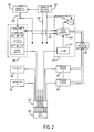
- FIG. 2 is a block diagram of an RF system that forms part of the MRI system of FIG. 1 ;
- FIG. 3 is a flowchart setting for the steps of an exemplary method for determining RF waveforms in accordance with the present invention.
- r [r x , r y , r z ] t is a spatial location
- an embodiment of the invention is employed in a magnetic resonance imaging (“MRI”) system.
- the MRI system includes a workstation 110 having a display 112 and a keyboard 114 .
- the workstation 110 includes a processor 116 that is a commercially available programmable machine running a commercially available operating system.
- the workstation 110 provides the operator interface that enables scan prescriptions to be entered into the MRI system.
- the workstation 110 is coupled to four servers: a pulse sequence server 118 ; a data acquisition server 120 ; a data processing server 122 , and a data store server 123 .
- the workstation 110 and each server 118 , 120 , 122 and 123 are connected to communicate with each other.
- the pulse sequence server 118 functions in response to instructions downloaded from the workstation 110 to operate a gradient system 124 and a radiofrequency (“RF”) system 126 .
- Gradient waveforms necessary to perform the prescribed scan are produced and applied to the gradient system 124 that excites gradient coils in an assembly 128 to produce the magnetic field gradients G x , G y , and G z used for position encoding MR signals.
- the gradient coil assembly 128 forms part of a magnet assembly 130 that includes a polarizing magnet 132 and a whole-body RF coil 134 .
- RF excitation waveforms are applied to the RF coil 134 by the RF system 126 to perform the prescribed magnetic resonance pulse sequence.
- Responsive MR signals detected by the RF coil 134 or a separate local coil are received by the RF system 126 , amplified, demodulated, filtered and digitized under direction of commands produced by the pulse sequence server 118 .
- the RF system 126 includes an RF transmitter for producing a wide variety of RF pulses used in MR pulse sequences.
- the RF transmitter is responsive to the scan prescription and direction from the pulse sequence server 118 to produce RF pulses of the desired frequency, phase and pulse amplitude waveform.
- the generated RF pulses may be applied to the whole body RF coil 134 or to one or more local coils or coil arrays (not shown in FIG. 1 ).
- the RF system 126 also includes one or more RF receiver channels.
- Each RF receiver channel includes an RF amplifier that amplifies the MR signal received by the coil to which it is connected and a detector that detects and digitizes the I and Q quadrature components of the received MR signal.
- phase of the received MR signal may also be determined:
- the pulse sequence server 118 also optionally receives patient data from a physiological acquisition controller 136 .
- the controller 136 receives signals from a number of different sensors connected to the patient, such as ECG signals from electrodes or respiratory signals from a bellows. Such signals are typically used by the pulse sequence server 118 to synchronize, or “gate,” the performance of the scan with the subject's respiration or heart beat.
- the pulse sequence server 118 also connects to a scan room interface circuit 138 that receives signals from various sensors associated with the condition of the patient and the magnet system. It is also through the scan room interface circuit 138 that a patient positioning system 140 receives commands to move the patient to desired positions during the scan.
- the digitized MR signal samples produced by the RF system 126 are received by the data acquisition server 120 .
- the data acquisition server 120 operates in response to instructions downloaded from the workstation 110 to receive the real-time MR data and provide buffer storage such that no data is lost by data overrun. In some scans the data acquisition server 120 does little more than pass the acquired MR data to the data processor server 122 . However, in scans that require information derived from acquired MR data to control the further performance of the scan, the data acquisition server 120 is programmed to produce such information and convey it to the pulse sequence server 118 . For example, during prescans MR data is acquired and used to calibrate the pulse sequence performed by the pulse sequence server 118 .
- navigator signals may be acquired during a scan and used to adjust RF or gradient system operating parameters or to control the view order in which k-space is sampled.
- the data acquisition server 120 may be employed to process MR signals used to detect the arrival of contrast agent in a magnetic resonance angiography (“MRA”) scan. In all these examples the data acquisition server 120 acquires MR data and processes it in real-time to produce information that is used to control the scan.
- MRA magnetic resonance angiography
- the data processing server 122 receives MR data from the data acquisition server 120 and processes it in accordance with instructions downloaded from the workstation 110 .
- processing may include, for example: Fourier transformation of raw k-space MR data to produce two or three-dimensional images; the application of filters to a reconstructed image; the performance of a backprojection image reconstruction of acquired MR data; the calculation of functional MR images; the calculation of motion or flow images, etc.
- Images reconstructed by the data processing server 122 are conveyed back to the workstation 110 where they are stored.
- Real-time images are stored in a data base memory cache (not shown) from which they may be output to operator display 112 or a display 142 that is located near the magnet assembly 130 for use by attending physicians.
- Batch mode images or selected real time images are stored in a host database on disc storage 144 .
- the data processing server 122 notifies the data store server 123 on the workstation 110 .
- the workstation 110 may be used by an operator to archive the images, produce films, or send the images via a network to other facilities.
- the present invention employs a coil array 250 that includes a plurality of coil elements that can be separately driven by a plurality of RF transmitters to produce the prescribed RF field-of-excitation (“FOX”).
- the same coil array 250 can also be used with a plurality of receive channels, or in the alternative, the whole body RF coil 134 or a local RF coil can be used to acquire the MR signals.
- Many different coil array structures 250 may be used with the present invention, which, in part, maps the B 1 + RF excitation field produced by each coil array element.
- the RF system 126 includes a set of transmitters 200 that each produce a prescribed RF excitation field.
- the base, or carrier, frequency of this RF excitation field is produced under control of a frequency synthesizer 202 which receives a set of digital signals from the pulse sequence server 118 . These digital signals indicate the frequency and phase of the RF carrier signal produced at an output 204 .
- the RF carrier is applied to a modulator and up converter 206 in each transmitter 200 where its amplitude is modulated in response to a signal also received from the pulse sequence server 118 .
- the signal defines the envelope of the RF excitation pulse to be produced and is produced by sequentially reading out a series of stored digital values. These stored digital values may, be changed to enable any desired RF pulse envelope to be produced by each transmitter 200 .
- the magnitude of the RF excitation pulse produced at output 208 is attenuated by an exciter attenuator circuit 210 in each transmitter 200 , which receives a digital command from the pulse sequence server 118 .
- the attenuated RF excitation pulses are applied to a power amplifier 212 in each transmitter 200 .
- the power amplifiers are current source devices that connect to respective transmit inputs on a set of transmit/receive switches 214 .
- N transmitters 200 are employed and connected through N transmit/receive switches 214 to N coil elements in an RF coil array 200 .
- the signal produced by the subject is picked up by the coil array 200 and applied to the inputs of a set of receive channels 220 .
- a pre-amplifier 222 in each receiver channel 220 amplifies the signal by an amount determined by a digital attenuation signal received from the pulse sequence server 118 .
- the received signal is at or around the Larmor frequency, and this high frequency signal is down converted in a two step process by a down converter 224 , which first mixes the NMR signal with the carrier signal on line 204 and then mixes the resulting difference signal with a reference signal on line 226 .
- the down converter NMR signal is applied to the input of an analog-to-digital (“ND”) converter 228 which samples and digitizes the analog signal and applies it to a digital detector and signal processor 230 , which produces 16-bit in-phase (“I”) values and 16-bit quadrature (“Q”) values corresponding to the received signal.
- the resulting stream of digitized I and Q values of the received signal are output to the data acquisition server 120 .
- the reference signal as well as the sampling signal applied to the A/D converter 228 are produced by a reference frequency generator 232 .
- the transmit/receive switches 214 are operated by the pulse sequence server 118 to connect the N transmitters 200 to the N coil elements in the coil array 250 during those parts of the pulse sequence in which an RF field is to be produced.
- Each transmitter 200 is separately controlled by the pulse sequence server 118 to produce an RF field of a prescribed amplitude, frequency, phase and envelope at each of the N coil elements.
- the combined RF fields of the N coil elements produce the prescribed B 1 field throughout the region of interest in the subject during the imaging phase of the procedure.
- the pulse sequence server 118 operates the transmit/receive switches 214 to connect each of the N receive channels to the respective N coil elements. Signals produced by excited spins in the subject are picked up and separately processed as described above.
- Parallel excitation systems differ from their single-channel counterparts in that the parallel excitation systems include multiple RF excitation channels that are each capable of independent and simultaneous RF transmission.
- Current designs for parallel excitation systems are limited to single-frequency RF excitation with no control over RF excitation at other spectral frequencies. This is unfortunate, since there are many applications that require RF excitation to be performed well over a range of frequencies, or to excite different spatial patterns at different spectral frequency points.
- An example of such methods is chemical shift imaging (“CSI”). Proton chemical shift imaging gains SNR, and chemical shift dispersion benefits from higher B 0 field, but requires B 1 ⁇ mitigation over both a specified spectral bandwidth and a spatial FOV.
- CSI chemical shift imaging
- ⁇ the gyromagnetic ratio
- M 0 the steady-state magnetization
- m(r) the approximate transverse magnetization resulting from the transmission of the RF pulses
- S P (r) is the complex-valued B 1 + transmit profile of the p th coil
- b 1p (t) is the RF pulse played along the p th coil
- ⁇ B 0 (r) is a field map of B 0 inhomogeneity
- e i ⁇ B 0 (r)(t ⁇ L) is the phase accumulation resulting from the B 0 inhomogeneity
- L is the RF pulse duration
- k ⁇ ( t ) - ⁇ ⁇ ⁇ t L ⁇ G ⁇ ( ⁇ ) ⁇ ⁇ d ⁇ .
- S p is a diagonal matrix containing N s samples of the p th spatial profile within a user-selected field-of-excitation (“FOX”) and b p includes samples of the p th RF waveform, b 1,p (t).
- F the matrix, incorporates the effects of the B 0 inhomogeneity and relates the energy deposited along a contour in k-space to the corresponding spatial location at the N s sample points where each coil is sampled.
- F i ⁇ M 0 ⁇ t e i ⁇ B 0 (r)(t ⁇ L) e ir ⁇ k(t) Eqn. (4);
- ⁇ t is the time-sample spacing of the RF waveform, b l,p (t).
- ⁇ b ⁇ 2 2 denotes a Tikhonov regularization term that is used to control the integrated RF power and the optimization is performed over the region-of-interest (“ROI”) implied by a weighting, w.
- the MLS optimization as represented by
- LS least-squares
- the spectral-spatial RF excitation pulse design is a direct extension of the above formulation.
- the set of equations is extended, and the transverse magnetization vector, m , and the A matrix are concatenated in accordance with the N design frequencies (1, 2, . . . , N).
- the A matrix for each design frequency is calculated based on Eqn. (1), where the appropriate frequency offset is added to the B 0 inhomogeneity term of the equation.
- equation (3) takes on the form:
- Equation (6) can subsequently be solved, as before, using an MLS optimization technique with the appropriate substitutions of m and A with the corresponding matrices in Eqn. (6).
- the design of an RF pulse for spectral-spatial excitation is generally ill-conditioned when a conventional LS optimization method is employed because such methods require a fixed excitation phase. Therefore, an optimization method such as MLS is instead employed due to its ability to discern excitation profiles at different frequencies, which have different spatial phases.
- a B 0 inhomogeneity correction (e.g., B 0 tracking) is incorporated into the RF excitation pulse design by modifying the N individual A matrices in equation (6) to include a measured B 0 field map. This is achieved using a procedure similar to those described by W. Grissom, et al., in “Spatial Domain Method for the Design of RF Pulses in Multicoil Parallel Excitation,” Magn. Reson. Med., 2006; 56:620-629, and by K. Setsompop, et al., in “In Vivo Parallel RF Excitation with B 0 Correction,” Proc. Intl. Soc. Magn. Reson. Med., 2007; 671.
- the design of a spectral-spatial RF excitation pulse in accordance with the present invention begins by determining desired spatial and spectral excitation patterns, as indicated in step 300 . This is done, for example, by producing a matrix, d(r), having values indicative of the spatial extent of a desired pattern of transverse magnetization and by producing a matrix, d(f), having values indicative of a desired spectral bandwidth of a desired pattern of transverse magnetization. More specifically, the spectral excitation pattern indicates a plurality of desired resonance frequencies of spins that are to be excited in order to produce transverse magnetization.
- a particular design might prescribe uniform spatial excitation at 0 and 100 hertz (“Hz”) frequencies, and substantially no spatial excitation at 200 Hz.
- another type of spatial excitation pattern such as, substantially no excitation in the top half of the imaging field-of-view and uniform excitation in the bottom half, might be prescribed for only a single spectral frequency such as 300 Hz.
- the spatial profile of the RF transmission coil is estimated at step 302 .
- a plurality of spatial profiles, S p (r) are determined when a parallel RF transmission coil array is employed.
- only one profile, S 1 (r) is determined when employing a single channel transmission coil.
- the estimation of the spatial profile, S p (r), is achieved, for example, using the estimation method described in co-pending U.S. patent application Ser. No. 12/422,017 entitled “Method for Fast Magnetic Resonance Radiofrequency Coil Transmission Profile Mapping”; however, in the alternative, other methods may be employed.
- gradient waveforms, G(t), that define the k-space locations to which RF energy is to be deposited are determined. This is done, for example, by employing a method such as the one described by S. Saekho, et al., in “Small Tip Angle Three-Dimensional Tailored Radiofrequency Slab-Select Pulse for Reduced B1 Inhomogeneity at 3T,” Magn. Reson. Med., 2005; 53 (2):479-484, or by Meyer, et al., in “Simultaneous Spatial and Spectral Selective Excitation,” Magn. Reson. Med., 1990; 15(2):287-304. As described above, these gradient waveforms define the k-space locations that, when played out in the presence of the appropriate RF excitation pulses, produce the desired excitation pattern.
- a set of RF excitation waveforms that minimize the amount of RF energy required to produce the desired spatial-spectral excitation are subsequently produced, as indicated at step 306 .
- equation (6) is solved by an iterative process, as described above in detail.
- a magnitude least squares (“MLS”) optimization such as the one described in equation (5), is employed so that the magnitude of the RF energy can be improved while allowing for non-uniform phase variations.
- the result of employing such an optimization technique is a set of RF excitation waveforms that utilize a reduced expenditure of RF energy in order to produce a spatial-spectral excitation in accordance with the desired spatial and spectral excitation patterns established in step 300 .
- the desired spatial-spectral excitation pattern is produced.
- both the gradient and RF waveforms have been determined, they are sent to the MRI system hardware, as indicated at step 308 , so that they can be employed in an examination to produce the desired excitation.
- a reliable spatial-spectral excitation pattern is achievable with substantially suppressed effects from B 1 + -field inhomogeneities.
- spatial-spectral excitation patterns having desired performance characteristics over a prescribed spatial extent and spectral bandwidth are achievable. For example, RF excitation is produced at a certain spectral frequency while suppressing, that is, producing substantially no excitation, at another spectral frequency in accordance with a prescribed spatial pattern of excitation.
Landscapes
- Physics & Mathematics (AREA)
- General Physics & Mathematics (AREA)
- Condensed Matter Physics & Semiconductors (AREA)
- High Energy & Nuclear Physics (AREA)
- Nuclear Medicine, Radiotherapy & Molecular Imaging (AREA)
- Health & Medical Sciences (AREA)
- Spectroscopy & Molecular Physics (AREA)
- Radiology & Medical Imaging (AREA)
- Engineering & Computer Science (AREA)
- Signal Processing (AREA)
- General Health & Medical Sciences (AREA)
- Optics & Photonics (AREA)
- Vascular Medicine (AREA)
- Magnetic Resonance Imaging Apparatus (AREA)
Abstract
Description
M=√{square root over (I 2 +Q 2)},
m=S 1 Fb 1 + . . . +S P Fb P, Eqn. (2);
F=iγM 0Δt e iΔB
b=argb min{∥|Ab|−m∥ w 2 +β·∥b∥ 2 2} Eqn. (5);
Claims (16)
Priority Applications (1)
| Application Number | Priority Date | Filing Date | Title |
|---|---|---|---|
| US12/544,714 US8085044B2 (en) | 2008-08-20 | 2009-08-20 | Method for producing spectral-spatial parallel RF excitation pulses for magnetic resonance imaging |
Applications Claiming Priority (2)
| Application Number | Priority Date | Filing Date | Title |
|---|---|---|---|
| US9025608P | 2008-08-20 | 2008-08-20 | |
| US12/544,714 US8085044B2 (en) | 2008-08-20 | 2009-08-20 | Method for producing spectral-spatial parallel RF excitation pulses for magnetic resonance imaging |
Publications (2)
| Publication Number | Publication Date |
|---|---|
| US20100156411A1 US20100156411A1 (en) | 2010-06-24 |
| US8085044B2 true US8085044B2 (en) | 2011-12-27 |
Family
ID=42265057
Family Applications (1)
| Application Number | Title | Priority Date | Filing Date |
|---|---|---|---|
| US12/544,714 Active 2030-01-28 US8085044B2 (en) | 2008-08-20 | 2009-08-20 | Method for producing spectral-spatial parallel RF excitation pulses for magnetic resonance imaging |
Country Status (1)
| Country | Link |
|---|---|
| US (1) | US8085044B2 (en) |
Cited By (1)
| Publication number | Priority date | Publication date | Assignee | Title |
|---|---|---|---|---|
| US20150309147A1 (en) * | 2014-04-25 | 2015-10-29 | Deere & Company | Systems and Methods For Designing Magnetic Resonance Imaging Radio Frequency Pulses That Are Robust Against Physiological Motion Errors |
Families Citing this family (5)
| Publication number | Priority date | Publication date | Assignee | Title |
|---|---|---|---|---|
| US9775557B2 (en) * | 2013-04-03 | 2017-10-03 | Vanderbilt University | Quantifying breast tissue changes with spectrally selective MRI and MRS |
| US11874353B2 (en) | 2019-03-27 | 2024-01-16 | The General Hospital Corporation | Multi-shot echo planar imaging using reordered segments and recursive radio frequency pulse design giving matched slice profiles across segments |
| DE102020202830A1 (en) * | 2020-03-05 | 2021-09-09 | Siemens Healthcare Gmbh | Magnetic resonance tomograph and method for operation with dynamic B0 compensation |
| WO2021247857A1 (en) * | 2020-06-03 | 2021-12-09 | The Brigham And Women's Hospital, Inc. | System and methods for ultra-fast multi-dimensional diffusion-relaxation mri using time-division multiplexing sequences |
| CN114089242B (en) * | 2021-11-03 | 2024-08-23 | 深圳市联影高端医疗装备创新研究院 | Excitation pulse design method, excitation pulse design device, computer equipment and storage medium |
Citations (7)
| Publication number | Priority date | Publication date | Assignee | Title |
|---|---|---|---|---|
| US6188219B1 (en) * | 1999-01-22 | 2001-02-13 | The Johns Hopkins University | Magnetic resonance imaging method and apparatus and method of calibrating the same |
| US7368910B2 (en) * | 2004-09-17 | 2008-05-06 | The Board Of Trustees Of The Leland Stanford Junior University | Dual gradient echo pulse sequence using interleaved spiral-out spiral-in k-space trajectories |
| US7466131B1 (en) * | 2007-04-20 | 2008-12-16 | General Electric Company | System and method for designing multi-channel RF pulses for MR imaging |
| US20090256570A1 (en) * | 2008-04-11 | 2009-10-15 | Zelinski Adam C | Method For Joint Sparsity-Enforced K-Space Trajectory and Radiofrequency Pulse Design |
| US7800368B2 (en) * | 2006-02-17 | 2010-09-21 | Regents Of The University Of Minnesota | High field magnetic resonance |
| US20100296714A1 (en) * | 2007-05-22 | 2010-11-25 | Imaging Biometrics, Llc | Multiparameter perfusion imaging with leakage correction |
| US7843195B2 (en) * | 2008-04-30 | 2010-11-30 | Bruker Biospin Mri Gmbh | Method for determining the spatial distribution of magnetic resonance signals with use of local spatially encoding magnetic fields |
-
2009
- 2009-08-20 US US12/544,714 patent/US8085044B2/en active Active
Patent Citations (7)
| Publication number | Priority date | Publication date | Assignee | Title |
|---|---|---|---|---|
| US6188219B1 (en) * | 1999-01-22 | 2001-02-13 | The Johns Hopkins University | Magnetic resonance imaging method and apparatus and method of calibrating the same |
| US7368910B2 (en) * | 2004-09-17 | 2008-05-06 | The Board Of Trustees Of The Leland Stanford Junior University | Dual gradient echo pulse sequence using interleaved spiral-out spiral-in k-space trajectories |
| US7800368B2 (en) * | 2006-02-17 | 2010-09-21 | Regents Of The University Of Minnesota | High field magnetic resonance |
| US7466131B1 (en) * | 2007-04-20 | 2008-12-16 | General Electric Company | System and method for designing multi-channel RF pulses for MR imaging |
| US20100296714A1 (en) * | 2007-05-22 | 2010-11-25 | Imaging Biometrics, Llc | Multiparameter perfusion imaging with leakage correction |
| US20090256570A1 (en) * | 2008-04-11 | 2009-10-15 | Zelinski Adam C | Method For Joint Sparsity-Enforced K-Space Trajectory and Radiofrequency Pulse Design |
| US7843195B2 (en) * | 2008-04-30 | 2010-11-30 | Bruker Biospin Mri Gmbh | Method for determining the spatial distribution of magnetic resonance signals with use of local spatially encoding magnetic fields |
Cited By (2)
| Publication number | Priority date | Publication date | Assignee | Title |
|---|---|---|---|---|
| US20150309147A1 (en) * | 2014-04-25 | 2015-10-29 | Deere & Company | Systems and Methods For Designing Magnetic Resonance Imaging Radio Frequency Pulses That Are Robust Against Physiological Motion Errors |
| US10247803B2 (en) * | 2014-04-25 | 2019-04-02 | Regents Of The University Of Minnesota | Systems and methods for designing magnetic resonance imaging radio frequency pulses that are robust against physiological motion errors |
Also Published As
| Publication number | Publication date |
|---|---|
| US20100156411A1 (en) | 2010-06-24 |
Similar Documents
| Publication | Publication Date | Title |
|---|---|---|
| US9414766B2 (en) | Method for simultaneous multi-slice magnetic resonance imaging using single and multiple channel receiver coils | |
| US8076939B2 (en) | Method for fast magnetic resonance radiofrequency coil transmission profile mapping | |
| US9778336B2 (en) | System and method for rapid, multi-shot segmented magnetic resonance imaging | |
| US9778338B2 (en) | Method for simultaneous multi-slice magnetic resonance imaging | |
| US10684337B2 (en) | Multiband RF/MRI pulse design for multichannel transmitter | |
| US7397242B2 (en) | Parallel magnetic resonance imaging method using a radial acquisition trajectory | |
| US8154289B2 (en) | Method for joint sparsity-enforced k-space trajectory and radiofrequency pulse design | |
| US8148985B2 (en) | Method for reducing maximum local specific absorption rate in magnetic resonance imaging | |
| US8400152B2 (en) | Method for k-space reconstruction in magnetic resonance inverse imaging | |
| US8148984B2 (en) | Method for magnitude constrained phase contrast magnetic resonance imaging | |
| US5226418A (en) | Phase correction of complex - difference processed magnetic resonance angiograms | |
| US20100026297A1 (en) | Method for relaxation-compensated fast multi-slice chemical exchange saturation transfer mri | |
| US8698496B2 (en) | Method for two-dimensional correlation magnetic resonance spectroscopy | |
| US10459058B2 (en) | System and method for magnetic resonance imaging with prospective motion control | |
| US8085046B2 (en) | Coil array mode compression for parallel transmission magnetic resonance imaging | |
| US8274284B2 (en) | Parallel-accelerated complex subtraction MRI | |
| WO2007050698A2 (en) | Parallel magnetic resonance imaging method using a radial acquisition trajectory | |
| US10338180B2 (en) | System and method for gradient measurement using single-point imaging | |
| US8085044B2 (en) | Method for producing spectral-spatial parallel RF excitation pulses for magnetic resonance imaging | |
| US8334696B2 (en) | Method for magnetic resonance imaging with parallel and localized spatial encoding magnetic fields | |
| US10845446B2 (en) | System and method for determining patient parameters using radio frequency phase increments in magnetic resonance imaging | |
| US9316711B2 (en) | System and method for accelerated magnetic resonance imaging using spectral sensitivity | |
| WO2017132182A1 (en) | Systems and methods for joint reconstruction of quantitative t2 and adc maps | |
| US8334694B2 (en) | System and method for embedded self-calibration within an inversion recovery pulse sequence |
Legal Events
| Date | Code | Title | Description |
|---|---|---|---|
| AS | Assignment |
Owner name: NATIONAL INSTITUTES OF HEALTH (NIH), U.S. DEPT. OF Free format text: CONFIRMATORY LICENSE;ASSIGNOR:GENERAL HOSPITAL CORPORATION DBA MASS;REEL/FRAME:023960/0166 Effective date: 20100219 |
|
| STCF | Information on status: patent grant |
Free format text: PATENTED CASE |
|
| AS | Assignment |
Owner name: MASSACHUSETTS INSTITUTE OF TECHNOLOGY, MASSACHUSET Free format text: ASSIGNMENT OF ASSIGNORS INTEREST;ASSIGNORS:SETSOMPOP, KAWIN;GAGOSKI, BORJAN A.;ADALSTEINSSON, ELFAR;SIGNING DATES FROM 20091015 TO 20100304;REEL/FRAME:028041/0248 Owner name: THE GENERAL HOSPITAL CORPORATION, MASSACHUSETTS Free format text: ASSIGNMENT OF ASSIGNORS INTEREST;ASSIGNORS:ALAGAPPAN, VIJAYANAND;WALD, LAWRENCE L.;SIGNING DATES FROM 20090930 TO 20091016;REEL/FRAME:028041/0152 |
|
| FEPP | Fee payment procedure |
Free format text: PAT HOLDER CLAIMS SMALL ENTITY STATUS, ENTITY STATUS SET TO SMALL (ORIGINAL EVENT CODE: LTOS); ENTITY STATUS OF PATENT OWNER: SMALL ENTITY |
|
| FPAY | Fee payment |
Year of fee payment: 4 |
|
| MAFP | Maintenance fee payment |
Free format text: PAYMENT OF MAINTENANCE FEE, 8TH YR, SMALL ENTITY (ORIGINAL EVENT CODE: M2552); ENTITY STATUS OF PATENT OWNER: SMALL ENTITY Year of fee payment: 8 |
|
| MAFP | Maintenance fee payment |
Free format text: PAYMENT OF MAINTENANCE FEE, 12TH YR, SMALL ENTITY (ORIGINAL EVENT CODE: M2553); ENTITY STATUS OF PATENT OWNER: SMALL ENTITY Year of fee payment: 12 |