US8084118B1 - Plate member joining structure - Google Patents
Plate member joining structure Download PDFInfo
- Publication number
- US8084118B1 US8084118B1 US12/870,801 US87080110A US8084118B1 US 8084118 B1 US8084118 B1 US 8084118B1 US 87080110 A US87080110 A US 87080110A US 8084118 B1 US8084118 B1 US 8084118B1
- Authority
- US
- United States
- Prior art keywords
- plate member
- bonding face
- binding
- metal plate
- joining structure
- Prior art date
- Legal status (The legal status is an assumption and is not a legal conclusion. Google has not performed a legal analysis and makes no representation as to the accuracy of the status listed.)
- Expired - Fee Related
Links
- 238000005304 joining Methods 0.000 title claims abstract description 21
- 239000002184 metal Substances 0.000 claims abstract description 41
- 238000000465 moulding Methods 0.000 claims abstract description 10
- 238000005520 cutting process Methods 0.000 claims description 5
- 238000004519 manufacturing process Methods 0.000 description 7
- 238000000926 separation method Methods 0.000 description 6
- 239000000853 adhesive Substances 0.000 description 5
- 230000001070 adhesive effect Effects 0.000 description 5
- 230000002708 enhancing effect Effects 0.000 description 2
- 238000000034 method Methods 0.000 description 2
- 239000011248 coating agent Substances 0.000 description 1
- 238000000576 coating method Methods 0.000 description 1
- 230000002860 competitive effect Effects 0.000 description 1
- 238000009713 electroplating Methods 0.000 description 1
- 238000005516 engineering process Methods 0.000 description 1
- 238000001125 extrusion Methods 0.000 description 1
- 239000012530 fluid Substances 0.000 description 1
- 239000000463 material Substances 0.000 description 1
- 238000012986 modification Methods 0.000 description 1
- 230000004048 modification Effects 0.000 description 1
- 238000004381 surface treatment Methods 0.000 description 1
- 238000009834 vaporization Methods 0.000 description 1
- 230000008016 vaporization Effects 0.000 description 1
- 230000003313 weakening effect Effects 0.000 description 1
Images


Classifications
-
- B—PERFORMING OPERATIONS; TRANSPORTING
- B32—LAYERED PRODUCTS
- B32B—LAYERED PRODUCTS, i.e. PRODUCTS BUILT-UP OF STRATA OF FLAT OR NON-FLAT, e.g. CELLULAR OR HONEYCOMB, FORM
- B32B15/00—Layered products comprising a layer of metal
- B32B15/04—Layered products comprising a layer of metal comprising metal as the main or only constituent of a layer, which is next to another layer of the same or of a different material
- B32B15/08—Layered products comprising a layer of metal comprising metal as the main or only constituent of a layer, which is next to another layer of the same or of a different material of synthetic resin
-
- B—PERFORMING OPERATIONS; TRANSPORTING
- B29—WORKING OF PLASTICS; WORKING OF SUBSTANCES IN A PLASTIC STATE IN GENERAL
- B29C—SHAPING OR JOINING OF PLASTICS; SHAPING OF MATERIAL IN A PLASTIC STATE, NOT OTHERWISE PROVIDED FOR; AFTER-TREATMENT OF THE SHAPED PRODUCTS, e.g. REPAIRING
- B29C37/00—Component parts, details, accessories or auxiliary operations, not covered by group B29C33/00 or B29C35/00
- B29C37/0078—Measures or configurations for obtaining anchoring effects in the contact areas between layers
- B29C37/0082—Mechanical anchoring
-
- B—PERFORMING OPERATIONS; TRANSPORTING
- B32—LAYERED PRODUCTS
- B32B—LAYERED PRODUCTS, i.e. PRODUCTS BUILT-UP OF STRATA OF FLAT OR NON-FLAT, e.g. CELLULAR OR HONEYCOMB, FORM
- B32B3/00—Layered products comprising a layer with external or internal discontinuities or unevennesses, or a layer of non-planar form; Layered products having particular features of form
- B32B3/02—Layered products comprising a layer with external or internal discontinuities or unevennesses, or a layer of non-planar form; Layered products having particular features of form characterised by features of form at particular places, e.g. in edge regions
- B32B3/06—Layered products comprising a layer with external or internal discontinuities or unevennesses, or a layer of non-planar form; Layered products having particular features of form characterised by features of form at particular places, e.g. in edge regions for securing layers together; for attaching the product to another member, e.g. to a support, or to another product, e.g. groove/tongue, interlocking
-
- B—PERFORMING OPERATIONS; TRANSPORTING
- B32—LAYERED PRODUCTS
- B32B—LAYERED PRODUCTS, i.e. PRODUCTS BUILT-UP OF STRATA OF FLAT OR NON-FLAT, e.g. CELLULAR OR HONEYCOMB, FORM
- B32B7/00—Layered products characterised by the relation between layers; Layered products characterised by the relative orientation of features between layers, or by the relative values of a measurable parameter between layers, i.e. products comprising layers having different physical, chemical or physicochemical properties; Layered products characterised by the interconnection of layers
- B32B7/04—Interconnection of layers
-
- Y—GENERAL TAGGING OF NEW TECHNOLOGICAL DEVELOPMENTS; GENERAL TAGGING OF CROSS-SECTIONAL TECHNOLOGIES SPANNING OVER SEVERAL SECTIONS OF THE IPC; TECHNICAL SUBJECTS COVERED BY FORMER USPC CROSS-REFERENCE ART COLLECTIONS [XRACs] AND DIGESTS
- Y10—TECHNICAL SUBJECTS COVERED BY FORMER USPC
- Y10T—TECHNICAL SUBJECTS COVERED BY FORMER US CLASSIFICATION
- Y10T428/00—Stock material or miscellaneous articles
- Y10T428/24—Structurally defined web or sheet [e.g., overall dimension, etc.]
- Y10T428/24273—Structurally defined web or sheet [e.g., overall dimension, etc.] including aperture
- Y10T428/24281—Struck out portion type
- Y10T428/24289—Embedded or interlocked
-
- Y—GENERAL TAGGING OF NEW TECHNOLOGICAL DEVELOPMENTS; GENERAL TAGGING OF CROSS-SECTIONAL TECHNOLOGIES SPANNING OVER SEVERAL SECTIONS OF THE IPC; TECHNICAL SUBJECTS COVERED BY FORMER USPC CROSS-REFERENCE ART COLLECTIONS [XRACs] AND DIGESTS
- Y10—TECHNICAL SUBJECTS COVERED BY FORMER USPC
- Y10T—TECHNICAL SUBJECTS COVERED BY FORMER US CLASSIFICATION
- Y10T428/00—Stock material or miscellaneous articles
- Y10T428/24—Structurally defined web or sheet [e.g., overall dimension, etc.]
- Y10T428/24479—Structurally defined web or sheet [e.g., overall dimension, etc.] including variation in thickness
- Y10T428/24612—Composite web or sheet
-
- Y—GENERAL TAGGING OF NEW TECHNOLOGICAL DEVELOPMENTS; GENERAL TAGGING OF CROSS-SECTIONAL TECHNOLOGIES SPANNING OVER SEVERAL SECTIONS OF THE IPC; TECHNICAL SUBJECTS COVERED BY FORMER USPC CROSS-REFERENCE ART COLLECTIONS [XRACs] AND DIGESTS
- Y10—TECHNICAL SUBJECTS COVERED BY FORMER USPC
- Y10T—TECHNICAL SUBJECTS COVERED BY FORMER US CLASSIFICATION
- Y10T428/00—Stock material or miscellaneous articles
- Y10T428/31504—Composite [nonstructural laminate]
- Y10T428/31678—Of metal
Definitions
- the present invention relates to plate member joining structures and more particularly, to a plate member joining structure formed of a metal plate member and a plastic plate member that are joined together by insert molding to avoid separation.
- the design concept of commercial electronic products is focused on light, thin, short and small characteristics. Many electronic products (cell phone, notebook, PDA, etc.) are made convenient to carry by user. To enhance mobility, the weight of electronic products must be reduced.
- the shell or casing of an electronic product may be formed of an outer metal layer having a relatively thinner wall thickness and an inner plastic layer having a relatively thicker wall thickness. This design greatly reduces the product weight while providing excellent tensile strength. Further, the outer metal layer facilitates surface treatment by an electroplating or coating technique. Therefore, metal is commonly used for the casing or the outer layer of the casing for commercial electronic products.
- the metal plate member and the plastic plate member are separately made, complicating the manufacturing process and increasing the manufacturing cost.
- the volume of the adhesive is slightly reduced (due to vaporization of fluid), and tiny open spaces may exist in between the metal plate member and the plastic plate member, lowering the product yield rate.
- the metal plate member and the plastic plate member may be twisted when the user opens or closes the electronic product, and the torsional force thus produced may cause separation of the adhesive from the metal plate member and/or the plastic plate member, resulting in plate member separation damage.
- the present invention has been accomplished under the circumstances in view. It is the main object of the present invention to provide a plate member joining structure formed of a metal plate member and a plastic plate member, which has high tensile strength and which avoids separation between the metal plate member and the plastic plate member.
- a plate member joining structure comprises a metal plate member having opposing outer face and bonding face and a plastic plate member directly molded on the bonding face of the metal plate member by insert molding.
- the metal plate member has binding units located on the bonding face.
- Each binding unit comprises a plurality of binding strips formed of a part of the bonding face and curvedly protruded from the bonding face and arranged in a spiral manner. The binding strips are embedded in the plastic plate member to enhance the binding strength between the metal plate member and the plastic plate member.
- FIG. 1 is an elevational view of a part of a metal plate member for plate member joining structure in accordance with a first embodiment of the present invention.
- FIG. 2 is a schematic drawing illustrating a cutting tool used for the production of the plate member joining structure in accordance with the first embodiment of the present invention.
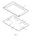
- FIG. 3 is an exploded view of a plate member joining structure in accordance with the first embodiment of the present invention.
- FIG. 4 is an elevational view of the plate member joining structure in accordance with the first embodiment of the present invention.
- FIG. 5 is a schematic perspective view, in an enlarged scale, of a part of the plate member joining structure in accordance with the first embodiment of the present invention.
- FIG. 6 is a sectional elevation in an enlarged scale of a part of the plate member joining structure in accordance with the first embodiment of the present invention.
- FIG. 7 is an elevational view of a part of a metal plate member for plate member joining structure in accordance with a second embodiment of the present invention.
- FIG. 8 is a schematic perspective view, in an enlarged scale, of a part of the plate member joining structure in accordance with the second embodiment of the present invention.
- a plate member joining structure in accordance with the present invention comprises a metal plate member 1 .
- the metal plate member 1 has opposing outer face 12 and bonding face 11 , and a plurality of binding units 13 located on the bonding face 11 .
- Each binding unit 13 includes a plurality of binding strips 131 formed of a part of the bonding face 11 and respectively curvedly protruded from the bonding face 11 and arranged in a spiral manner.
- Each binding unit 13 is formed by using a cutting tool 3 to cut and rotatably lift a part of the bonding face 11 .
- a cutting tool 3 is used and operated to cut the bonding face 11 of the metal plate member 1 so that an array of binding units 13 is formed at the bonding face 11 .
- the metal plate member 1 is put in an insert molding machine (not shown) and then a plastic plate member 2 is molded on the bonding face 11 of the metal plate member 1 by insert molding.
- the binding strips 131 of the binding units 13 are embedded in the plastic plate member 2 , i.e., the metal plate member 1 and the plastic plate member 2 are tightly bonded together.
- each binding unit 13 of the metal plate member 1 comprises a plurality of binding strips 131 formed of a part of the bonding face 11 and respectively curvedly extending from the bonding face 11 at a predetermined angle and arranged in a spiral manner, two side ribs 132 bilaterally connected between the bonding face 11 and each binding strip 131 , and a chamber 133 formed in the bonding face 11 and surrounded by one binding strip 131 and the associating two side ribs 132 .
- the binding strips 131 and side ribs 132 of the binding units 13 are embedded in the plastic plate member 2 , and the plastic material of the plastic plate member 2 filled up the chambers 133 , enhancing the binding strength between the metal plate member 1 and the plastic plate member 2 .
- the invention provides a plate member joining structure that has the advantages over the prior art designs subject to the technical features as follows:
- the binding strips 131 of the binding units 13 are embedded in the plastic plate member 2 , enhancing the binding strength between the metal plate member 1 and the plastic plate member 2 and avoiding separation between the metal plate member 1 and the plastic plate member 2 .
- each binding unit 13 is arranged in a spiral manner so that the binding strips 131 can enhance the torsional strength of the finished plate member joining structure, avoiding separation between the metal plate member 1 and the plastic plate member 2 .
- the binding units 13 are formed at the bonding face 11 by means of using a cutting tool 3 to lift a part of the bonding face 11 of the metal plate member 1 but not by means of extrusion deformation, the outer face 12 is kept intact.
- the invention has the characteristics of simple manufacturing process and low manufacturing cost.
Abstract
Description
Claims (3)
Priority Applications (1)
| Application Number | Priority Date | Filing Date | Title |
|---|---|---|---|
| US12/870,801 US8084118B1 (en) | 2010-08-28 | 2010-08-28 | Plate member joining structure |
Applications Claiming Priority (1)
| Application Number | Priority Date | Filing Date | Title |
|---|---|---|---|
| US12/870,801 US8084118B1 (en) | 2010-08-28 | 2010-08-28 | Plate member joining structure |
Publications (1)
| Publication Number | Publication Date |
|---|---|
| US8084118B1 true US8084118B1 (en) | 2011-12-27 |
Family
ID=45349818
Family Applications (1)
| Application Number | Title | Priority Date | Filing Date |
|---|---|---|---|
| US12/870,801 Expired - Fee Related US8084118B1 (en) | 2010-08-28 | 2010-08-28 | Plate member joining structure |
Country Status (1)
| Country | Link |
|---|---|
| US (1) | US8084118B1 (en) |
Cited By (2)
| Publication number | Priority date | Publication date | Assignee | Title |
|---|---|---|---|---|
| US20120121867A1 (en) * | 2010-11-17 | 2012-05-17 | Chin-Hsing Horng | Metal plate member for the fabrication of a composite plate member |
| USD793929S1 (en) * | 2015-07-07 | 2017-08-08 | Yuan-Hung WEN | Brake backing plate with heat sink |
Citations (1)
| Publication number | Priority date | Publication date | Assignee | Title |
|---|---|---|---|---|
| US5656353A (en) * | 1995-06-27 | 1997-08-12 | Tba Composites, Inc. | Laminated heat shield with prongs and method of manufacturing same |
-
2010
- 2010-08-28 US US12/870,801 patent/US8084118B1/en not_active Expired - Fee Related
Patent Citations (1)
| Publication number | Priority date | Publication date | Assignee | Title |
|---|---|---|---|---|
| US5656353A (en) * | 1995-06-27 | 1997-08-12 | Tba Composites, Inc. | Laminated heat shield with prongs and method of manufacturing same |
Cited By (2)
| Publication number | Priority date | Publication date | Assignee | Title |
|---|---|---|---|---|
| US20120121867A1 (en) * | 2010-11-17 | 2012-05-17 | Chin-Hsing Horng | Metal plate member for the fabrication of a composite plate member |
| USD793929S1 (en) * | 2015-07-07 | 2017-08-08 | Yuan-Hung WEN | Brake backing plate with heat sink |
Similar Documents
| Publication | Publication Date | Title |
|---|---|---|
| WO2009041506A1 (en) | Member for conductor connection, method for manufacturing the same, connection structure, and solar cell module | |
| WO2010066348A3 (en) | Ferroelectret double and multilayer composite and method for production thereof | |
| AU2002343553A1 (en) | Method of thermoforming a bladder structure | |
| WO2009023369A8 (en) | Fluid-filled chambers with foam tensile members and methods for manufacturing the chambers | |
| WO2005104210A3 (en) | Arrayed ultrasonic transducer | |
| US8187694B2 (en) | Composite plate member | |
| US20150367609A1 (en) | Bending wood laminate and bent shaped part produced therefrom | |
| US20110111176A1 (en) | Shell body with a plastic member molded onto a glass panel, and method for manufacturing the shell body | |
| US8084118B1 (en) | Plate member joining structure | |
| CN106663708B (en) | Including the positive photovoltaic module of polymer | |
| US8389104B2 (en) | Composite cores and panels | |
| CN113594593B (en) | Design method of aluminum plastic film and aluminum plastic film | |
| US8349433B2 (en) | Multi-layer plate member bonding structure | |
| US8835017B2 (en) | Metal sheet member having high plastic bonding strength | |
| CN105822038A (en) | Multi-layer composite floor and production method thereof | |
| CN109733019A (en) | A kind of aluminium alloy compound plate | |
| KR102364469B1 (en) | Laminate Sheet for Battery Case Having Thickness Variation and Pouch-type Battery Case Manufactured Using the Same | |
| US20120121867A1 (en) | Metal plate member for the fabrication of a composite plate member | |
| KR101421682B1 (en) | Furniture board and manufacturing process of the same | |
| KR100519943B1 (en) | Honeycomb core , mold for honeycomb core and manufacturing method of honeycomb core | |
| KR100666845B1 (en) | Core for a sandwich panel manufactured by deep drawing and a sandwich panel thereof | |
| CN101327603A (en) | Bendable glued board and preparation method thereof | |
| WO2010123765A3 (en) | Thin bond line semiconductor packages | |
| US20130149595A1 (en) | Battery module and its adhesive strap | |
| WO2010055227A8 (en) | Structural element comprising wood and concrete |
Legal Events
| Date | Code | Title | Description |
|---|---|---|---|
| ZAAA | Notice of allowance and fees due |
Free format text: ORIGINAL CODE: NOA |
|
| ZAAB | Notice of allowance mailed |
Free format text: ORIGINAL CODE: MN/=. |
|
| STCF | Information on status: patent grant |
Free format text: PATENTED CASE |
|
| FPAY | Fee payment |
Year of fee payment: 4 |
|
| MAFP | Maintenance fee payment |
Free format text: PAYMENT OF MAINTENANCE FEE, 8TH YR, SMALL ENTITY (ORIGINAL EVENT CODE: M2552); ENTITY STATUS OF PATENT OWNER: SMALL ENTITY Year of fee payment: 8 |
|
| FEPP | Fee payment procedure |
Free format text: MAINTENANCE FEE REMINDER MAILED (ORIGINAL EVENT CODE: REM.); ENTITY STATUS OF PATENT OWNER: SMALL ENTITY |
|
| LAPS | Lapse for failure to pay maintenance fees |
Free format text: PATENT EXPIRED FOR FAILURE TO PAY MAINTENANCE FEES (ORIGINAL EVENT CODE: EXP.); ENTITY STATUS OF PATENT OWNER: SMALL ENTITY |
|
| STCH | Information on status: patent discontinuation |
Free format text: PATENT EXPIRED DUE TO NONPAYMENT OF MAINTENANCE FEES UNDER 37 CFR 1.362 |
|
| FP | Lapsed due to failure to pay maintenance fee |
Effective date: 20231227 |