US8083473B2 - Interface for a stamped stator and a one-way clutch - Google Patents
Interface for a stamped stator and a one-way clutch Download PDFInfo
- Publication number
- US8083473B2 US8083473B2 US12/290,291 US29029108A US8083473B2 US 8083473 B2 US8083473 B2 US 8083473B2 US 29029108 A US29029108 A US 29029108A US 8083473 B2 US8083473 B2 US 8083473B2
- Authority
- US
- United States
- Prior art keywords
- stamped
- blade
- segments
- stator
- axially extending
- Prior art date
- Legal status (The legal status is an assumption and is not a legal conclusion. Google has not performed a legal analysis and makes no representation as to the accuracy of the status listed.)
- Expired - Fee Related, expires
Links
Images


Classifications
-
- F—MECHANICAL ENGINEERING; LIGHTING; HEATING; WEAPONS; BLASTING
- F16—ENGINEERING ELEMENTS AND UNITS; GENERAL MEASURES FOR PRODUCING AND MAINTAINING EFFECTIVE FUNCTIONING OF MACHINES OR INSTALLATIONS; THERMAL INSULATION IN GENERAL
- F16H—GEARING
- F16H41/00—Rotary fluid gearing of the hydrokinetic type
- F16H41/24—Details
- F16H2041/246—Details relating to one way clutch of the stator
Definitions
- the invention relates to improvements in apparatus for transmitting force between a rotary driving unit (such as the engine of a motor vehicle) and a rotary driven unit (such as the variable-speed transmission in the motor vehicle).
- a rotary driving unit such as the engine of a motor vehicle
- a rotary driven unit such as the variable-speed transmission in the motor vehicle.
- the invention relates to means for connecting a stamped stator and a one-way clutch.
- the present invention broadly a comprises a blade assembly for a stator, including: a first stamped blade segment arranged to be rotationally connected to an outer race of the stator using at least one radially opening slot on an outer race for the stator; and a second stamped blade segment, separately formed from the first stamped blade segment, having an outer circumferential portion fixedly connected to an outer circumferential portion for the first stamped blade segment.
- the second stamped blade segment is arranged to be rotationally connected to the outer race using the at least one radially opening slot.
- the first and second stamped blade segments include at least one first and second portion, respectively, arranged to matingly engage with the at least one radially opening slot and disposed on respective portions of the first and second stamped blade segments disposed radially inward of respective blades in the first and second blade segments.
- the blade assembly includes at least one rivet arranged to be disposed in the at least one radially opening slot and fixedly secured to respective portions of the first and second stamped blade segments disposed radially inward of respective blades in the first and second blade segments.
- the first and second stamped blade segments include respective pluralities of openings and the at least one rivet includes a plurality of sheet metal rivets having respective portions disposed at respective openings in the respective pluralities of openings.
- the first and second stamped segments include first and second axially extending segments, respectively, arranged to center one or two bearings.
- the first axially extending segment includes at least one axially extending tab.
- the blade assembly includes a bushing arranged to be radially disposed between an axially extending portion of the first and/or the second stamped blade segment and an inner race for the one-way clutch to radially center the stator.
- the present invention also broadly comprises a stator, including: a one-way clutch with at least one slot opening radially outward from an outer circumferential portion of an outer race; and a blade assembly including a first stamped blade segment rotationally connected to the one-way clutch via the at least one slot; and a second stamped blade segment, separately formed from the first stamped blade segment and having an outer circumferential portion fixedly connected to an outer circumferential portion for the first stamped blade assembly.
- the second stamped blade segment is rotationally connected to the one-way clutch via the at least one slot.
- the first stamped blade segment includes a portion disposed in the at least one slot and disposed radially inward from blades for the first stamped blade segment and wherein the second stamped blade segment includes a portion disposed in the at least one slot and disposed radially inward from blades for the second stamped blade segment.
- the stator includes at least one rivet disposed in the at least one slot and fixedly secured to first and second portions of the first and second stamped blade segments, respectively, the first and second portions located radially inward from blades for the first and second stamped blade segments, respectively.
- the first and second stamped blade segments include respective pluralities of openings and the at least one rivet includes a plurality of sheet metal rivets disposed at respective openings in the respective pluralities of openings.
- the stator includes one or two bearings and the first and second stamped segments include first and second axially extending segments, respectively. The one or two bearings are radially centered by the first and second axially extending segments.
- the first axially extending segment includes at least one axially extending tab.
- the stator includes a bushing radially disposed between an axially extending portion of the first and/or second stamped blade segment and an inner race for the one-way clutch to radially center the stator.
- FIG. 1A is a perspective view of a cylindrical coordinate system demonstrating spatial terminology used in the present application
- FIG. 1B is a perspective view of an object in the cylindrical coordinate system of FIG. 1A demonstrating spatial terminology used in the present application;
- FIG. 2 is a front perspective view of a present invention stator with sheet metal rivets
- FIG. 3 is front view of the stator shown in FIG. 2 ;
- FIG. 4 is a cross-sectional view of the stator shown in FIG. 2 , generally along line 4 - 4 in FIG. 3 ;
- FIG. 5 is cross-sectional view of the stator shown in FIG. 2 generally along line 5 - 5 in FIG. 4 ;
- FIG. 6 is a front exploded view of a present invention stator with a spline connection.
- FIG. 7 is a partial cross-sectional view of the stator shown in FIG. 6 , generally along line 7 - 7 in FIG. 6 .
- FIG. 1A is a perspective view of cylindrical coordinate system 80 demonstrating spatial terminology used in the present application.
- the present invention is at least partially described within the context of a cylindrical coordinate system.
- System 80 has a longitudinal axis 81 , used as the reference for the directional and spatial terms that follow.
- the adjectives “axial,” “radial,” and “circumferential” are with respect to an orientation parallel to axis 81 , radius 82 (which is orthogonal to axis 81 ), and circumference 83 , respectively.
- the adjectives “axial,” “radial” and “circumferential” also are regarding orientation parallel to respective planes.
- objects 84 , 85 , and 86 are used.
- Surface 87 of object 84 forms an axial plane.
- axis 81 forms a line along the surface.
- Surface 88 of object 85 forms a radial plane. That is, radius 82 forms a line along the surface.
- Surface 89 of object 86 forms a circumferential plane. That is, circumference 83 forms a line along the surface.
- axial movement or disposition is parallel to axis 81
- radial movement or disposition is parallel to radius 82
- circumferential movement or disposition is parallel to circumference 83 .
- Rotation is with respect to axis 81 .
- the adverbs “axially,” “radially,” and “circumferentially” are with respect to an orientation parallel to axis 81 , radius 82 , or circumference 83 , respectively.
- the adverbs “axially,” “radially,” and “circumferentially” also are regarding orientation parallel to respective planes.
- FIG. 1B is a perspective view of object 90 in cylindrical coordinate system 80 of FIG. 1A demonstrating spatial terminology used in the present application.
- Cylindrical object 90 is representative of a cylindrical object in a cylindrical coordinate system and is not intended to limit the present invention in any manner.
- Object 90 includes axial surface 91 , radial surface 92 , and circumferential surface 93 .
- Surface 91 is part of an axial plane
- surface 92 is part of a radial plane
- surface 93 is part of a circumferential plane.
- a present invention stator includes a one-way clutch and a blade assembly including two stamped blade segments.
- the clutch includes at least one slot opening radially outward from an outer circumferential portion of an outer race and at least one of the two stamped blade segments are rotationally connected to the one-way clutch via the slot as further described infra.
- rotationally connected, or secured we mean that the clutch and the blade segments are connected such that the two components rotate together, that is, the two components are fixed with respect to rotation.
- Rotationally connecting two components does not necessarily limit relative movement in other directions. For example, it is possible for two components that are rotationally connected to have axial movement with respect to each other via a spline connection. However, it should be understood that rotational connection does not imply that movement in other directions is necessarily present.
- two components that are rotationally connected can be axially fixed one to the other.
- the preceding explanation of rotational connection is applicable to the discussions infra.
- the blade segments are fixedly secured one to the other at an outer circumference of the segments by any means known in the art.
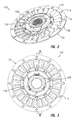
- FIG. 2 is a front perspective view of present invention stator 100 with sheet metal rivets.
- FIG. 3 is a front view of stator 100 shown in FIG. 2 .
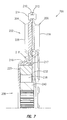
- FIG. 4 is partial cross-sectional view of stator 100 shown in FIG. 2 , generally along line 4 - 4 in FIG. 3 .
- FIG. 5 is cross-sectional view of stator 100 shown in FIG. 2 generally along line 5 - 5 in FIG. 4 .
- stator 100 includes blade assembly 102 with blade segments 104 and 106 , and one way clutch 108 .
- Outer circumferential portions 110 and 112 of segments 104 and 106 , respectively, are fixedly connected by rivets 114 ; however, it should be understood that the portions can be joined by other means, including, but not limited to threaded fasteners, tabs, and welding.
- at least portions of segments 104 and 106 are formed and configured as shown in commonly-owned U.S. patent application Ser. No. 11/728,066, filed Mar. 23, 2007.
- stator 100 includes at least one rivet 116 disposed in at least one radially opening slot 118 in outer race 120 of the clutch.
- radially opening we mean the opening for the slot is in a radial direction.
- Slots 118 are disposed in outer circumferential portion 121 of the race.
- Rivets 116 are fixedly secured to one or both of portions 122 and 124 , respectively, of blade segments 104 and 106 , respectively.
- Portions 122 and 124 are located radially inward from blades 126 and 128 , respectively, for blade segments 104 and 106 , respectively.
- Rivets 116 are rotationally connected to the clutch since the rivets are circumferentially interleaved with the outer race via the slots.
- Rivets 116 also axially fix portions 122 and 124 .
- Stator 100 is not limited to a particular size, shape, number, type, or configuration of rivets 116 .
- rivets 116 are sheet metal rivets having multiple heads.
- rivets 116 include a circumferential portion 130 disposed in slots 118 and heads 132 disposed at openings 134 and 135 in portions 122 and 124 , respectively.
- the heads are peened or otherwise expanded to overlap radial surfaces surrounding the openings.
- the clutch includes rollers 138 and inner race 140 .
- stator 100 is used in a torque converter (not shown) with one or two thrust bearings (not shown).
- Segments 104 and 106 include axially extending segments 142 and 144 , respectively, with which the one or two thrust bearings in placed in contact to radially center the bearings.
- segment 142 is a step formed in segment 104 and segment 144 is at least one axially extending tab.
- the stator includes bushing 146 radially disposed between one or both of segments 104 and 106 .
- the bushing is between portion 142 and inner race 140 . The bushing radially centers the stator.
- FIG. 6 is a front exploded view of present invention stator 200 with a spline connection.
- FIG. 7 is a partial cross-sectional view of stator 200 shown in FIG. 6 , generally along line 7 - 7 in FIG. 6 .
- stator 200 includes blade assembly 202 with blade segments 204 and 206 , and one way clutch 208 .
- Outer circumferential portions 210 and 212 of segments 204 and 206 , respectively, are fixedly connected by rivets 214 ; however, it should be understood that the portions can be joined by other means, including, but not limited to threaded fasteners, tabs, and welding.
- at least portions of segments 204 and 206 are formed and configured as shown in commonly-owned U.S. patent application Ser. No. 11/728,066, filed Mar. 23, 2007.
- segments 204 and 206 include portions 216 and 217 , respectively, disposed in at least one radially opening slot 218 in outer race 220 of the clutch.
- radially opening we mean the opening for the slot is in a radial direction.
- Slots 218 are disposed in outer circumferential portion 221 of the race.
- Segments 216 and 217 are disposed radially inward from blades 226 and 228 , respectively, for blade segments 204 and 206 , respectively. It should be understood that stator 200 also can include only portions 216 or only portions 217 .
- portions 216 are protrusions stamped or pressed radially inward from substantially axially oriented segment 230 .
- portions 217 are axially extending tabs formed from substantially radially oriented portion 232 .
- these embodiments of portions 216 and 217 can be formed by stamping processes.
- Portions 216 and 217 are rotationally connected to the clutch since the portions are circumferentially interleaved with the outer race via the slots. That is, as the blade assembly rotates, segments 216 and 217 engage respective radial walls for the slots. In a free wheel mode, the clutch rotates with the blade assembly. In a locked mode, the clutch is rotationally fixed and contact between segments 216 and 217 and the outer race also rotationally locks the blade assembly.
- the clutch includes rollers 238 and inner race 240 .
- stator 200 is used in a torque converter (not shown) with one or two thrust bearings (not shown).
- one or both of segments 204 and 206 include axially extending segments with which one or both of the thrust bearings are placed in contact to radially center the bearings.
- the axial segment in segment 204 is a step formed in segment 204 and the axial segment in segment 206 is at least one axially extending tab.
- the stator includes bushing (not shown) radially disposed between one or both of segments 204 and 206 .
- the stator includes a bushing radially disposed between the axial segment in segment 204 and inner race 240 . The bushing radially centers the stator.
Landscapes
- Engineering & Computer Science (AREA)
- General Engineering & Computer Science (AREA)
- Mechanical Engineering (AREA)
- Structures Of Non-Positive Displacement Pumps (AREA)
- Connection Of Plates (AREA)
Abstract
Description
Claims (19)
Priority Applications (1)
| Application Number | Priority Date | Filing Date | Title |
|---|---|---|---|
| US12/290,291 US8083473B2 (en) | 2007-10-31 | 2008-10-29 | Interface for a stamped stator and a one-way clutch |
Applications Claiming Priority (2)
| Application Number | Priority Date | Filing Date | Title |
|---|---|---|---|
| US113407P | 2007-10-31 | 2007-10-31 | |
| US12/290,291 US8083473B2 (en) | 2007-10-31 | 2008-10-29 | Interface for a stamped stator and a one-way clutch |
Publications (2)
| Publication Number | Publication Date |
|---|---|
| US20090110557A1 US20090110557A1 (en) | 2009-04-30 |
| US8083473B2 true US8083473B2 (en) | 2011-12-27 |
Family
ID=40514603
Family Applications (1)
| Application Number | Title | Priority Date | Filing Date |
|---|---|---|---|
| US12/290,291 Expired - Fee Related US8083473B2 (en) | 2007-10-31 | 2008-10-29 | Interface for a stamped stator and a one-way clutch |
Country Status (2)
| Country | Link |
|---|---|
| US (1) | US8083473B2 (en) |
| DE (1) | DE102008051107A1 (en) |
Families Citing this family (2)
| Publication number | Priority date | Publication date | Assignee | Title |
|---|---|---|---|---|
| WO2010006154A1 (en) * | 2008-07-10 | 2010-01-14 | Gkn Sinter Metals, Inc. | One-way clutch retainer |
| DE112017001461B4 (en) * | 2016-03-22 | 2024-01-04 | Schaeffler Technologies AG & Co. KG | One-way clutch assembly for a transmission |
Citations (4)
| Publication number | Priority date | Publication date | Assignee | Title |
|---|---|---|---|---|
| US4377068A (en) * | 1979-02-15 | 1983-03-22 | Daimler-Benz Aktiengesellschaft | Stator for a hydrodynamic torque converter |
| US5822987A (en) * | 1996-03-28 | 1998-10-20 | Aisin Aw Co., Ltd. | Stator and one way clutch assembly for a torque converter |
| US20070224042A1 (en) | 2006-03-24 | 2007-09-27 | Luk Lamellen Und Kupplungsbau Beteiligungs Kg | Two-part stator blade |
| US7770707B2 (en) * | 2005-08-24 | 2010-08-10 | Luk Lamellen Und Kupplungsbau Beteiligungs Kg | Axially engaging and disengaging one-way clutch and a stator having an axially engaging and disengaging one-way clutch |
-
2008
- 2008-10-09 DE DE102008051107A patent/DE102008051107A1/en not_active Ceased
- 2008-10-29 US US12/290,291 patent/US8083473B2/en not_active Expired - Fee Related
Patent Citations (5)
| Publication number | Priority date | Publication date | Assignee | Title |
|---|---|---|---|---|
| US4377068A (en) * | 1979-02-15 | 1983-03-22 | Daimler-Benz Aktiengesellschaft | Stator for a hydrodynamic torque converter |
| US5822987A (en) * | 1996-03-28 | 1998-10-20 | Aisin Aw Co., Ltd. | Stator and one way clutch assembly for a torque converter |
| US7770707B2 (en) * | 2005-08-24 | 2010-08-10 | Luk Lamellen Und Kupplungsbau Beteiligungs Kg | Axially engaging and disengaging one-way clutch and a stator having an axially engaging and disengaging one-way clutch |
| US20070224042A1 (en) | 2006-03-24 | 2007-09-27 | Luk Lamellen Und Kupplungsbau Beteiligungs Kg | Two-part stator blade |
| US7850420B2 (en) * | 2006-03-24 | 2010-12-14 | Schaeffler Technologies Gmbh & Co. Kg | Two-part stator blade |
Also Published As
| Publication number | Publication date |
|---|---|
| US20090110557A1 (en) | 2009-04-30 |
| DE102008051107A1 (en) | 2009-05-07 |
Similar Documents
| Publication | Publication Date | Title |
|---|---|---|
| US8453439B2 (en) | Torque converter turbine side bearing centering and retention on the stator | |
| US8439764B2 (en) | Drive plate with lanced drive tabs | |
| US6837348B2 (en) | Hydrodynamic clutch device | |
| JP6362628B2 (en) | One-way clutch carrier assembly | |
| US20150037158A1 (en) | Torque converter with stamped stator | |
| US8127905B2 (en) | Series damper with hysteresis in one damper | |
| US20110315498A1 (en) | Torque converter with improved torque converter clutch performance | |
| US8152646B2 (en) | Damper with two-piece plate configuration | |
| JP2008157461A (en) | Axial one-way clutch with axial spacer | |
| US7757828B2 (en) | Clutch attached to an outer rim of a torque converter | |
| CN110352312A (en) | torque converter | |
| US8083473B2 (en) | Interface for a stamped stator and a one-way clutch | |
| US8899032B2 (en) | Stator centering plate | |
| US8739524B2 (en) | Torque converter pump hub with profiled assembly surface | |
| US8382598B2 (en) | Modularity spacer for a damper | |
| US8944229B2 (en) | Clutch housing with wide lever spring retention slots and clutch housing with axially off-set tabs | |
| US10054206B2 (en) | Turbine shell with integrated stiffening elements | |
| US8047346B2 (en) | Pilot for a series damper | |
| US9080635B2 (en) | Hardened turbine plate | |
| US8607556B2 (en) | Damper assembly with Coulomb dampening and rivet access | |
| CN103797276B (en) | Locking device for torque converter | |
| US9212705B2 (en) | Torque converter with an input shaft centering feature | |
| US20090148090A1 (en) | Stamped inner or outer races | |
| US20090159387A1 (en) | Ratchet one way clutch with hardened blocking plate | |
| JP6285796B2 (en) | Lock-up device |
Legal Events
| Date | Code | Title | Description |
|---|---|---|---|
| AS | Assignment |
Owner name: LUK LAMELLEN UND KUPPLUNGSBAU BETEILIGUNGS KG, GER Free format text: ASSIGNMENT OF ASSIGNORS INTEREST;ASSIGNOR:BREES, WILLIAM;REEL/FRAME:022005/0689 Effective date: 20081218 |
|
| AS | Assignment |
Owner name: SCHAEFFLER TECHNOLOGIES GMBH & CO. KG, GERMANY Free format text: ASSIGNMENT OF ASSIGNORS INTEREST;ASSIGNOR:LUK VERMOEGENSVERWALTUNGSGESELLSCHAFT MBH;REEL/FRAME:027244/0363 Effective date: 20110926 Owner name: LUK VERMOEGENSVERWALTUNGSGESELLSCHAFT MBH, GERMANY Free format text: MERGER;ASSIGNOR:LUK LAMELLEN UND KUPPLUNGSBAU BETEILIGUNGS KG;REEL/FRAME:027244/0897 Effective date: 20100630 |
|
| REMI | Maintenance fee reminder mailed | ||
| LAPS | Lapse for failure to pay maintenance fees | ||
| STCH | Information on status: patent discontinuation |
Free format text: PATENT EXPIRED DUE TO NONPAYMENT OF MAINTENANCE FEES UNDER 37 CFR 1.362 |
|
| STCH | Information on status: patent discontinuation |
Free format text: PATENT EXPIRED DUE TO NONPAYMENT OF MAINTENANCE FEES UNDER 37 CFR 1.362 |
|
| AS | Assignment |
Owner name: SCHAEFFLER TECHNOLOGIES AG & CO. KG, GERMANY Free format text: CHANGE OF NAME;ASSIGNOR:SCHAEFFLER TECHNOLOGIES GMBH & CO. KG;REEL/FRAME:037731/0834 Effective date: 20120101 Owner name: SCHAEFFLER TECHNOLOGIES AG & CO. KG, GERMANY Free format text: CHANGE OF NAME;ASSIGNOR:SCHAEFFLER TECHNOLOGIES GMBH & CO. KG;REEL/FRAME:037732/0347 Effective date: 20150101 Owner name: SCHAEFFLER TECHNOLOGIES GMBH & CO. KG, GERMANY Free format text: MERGER AND CHANGE OF NAME;ASSIGNORS:SCHAEFFLER TECHNOLOGIES AG & CO. KG;SCHAEFFLER VERWALTUNGS 5 GMBH;REEL/FRAME:037732/0228 Effective date: 20131231 |
|
| FP | Lapsed due to failure to pay maintenance fee |
Effective date: 20151227 |
|
| AS | Assignment |
Owner name: SCHAEFFLER TECHNOLOGIES AG & CO. KG, GERMANY Free format text: CORRECTIVE ASSIGNMENT TO CORRECT THE PROPERTY NUMBERS PREVIOUSLY RECORDED ON REEL 037732 FRAME 0347. ASSIGNOR(S) HEREBY CONFIRMS THE APP. NO. 14/553248 SHOULD BE APP. NO. 14/553258;ASSIGNOR:SCHAEFFLER TECHNOLOGIES GMBH & CO. KG;REEL/FRAME:040404/0530 Effective date: 20150101 |