US8080792B2 - Active adaptive thermal stealth system - Google Patents
Active adaptive thermal stealth system Download PDFInfo
- Publication number
- US8080792B2 US8080792B2 US12/679,686 US67968608A US8080792B2 US 8080792 B2 US8080792 B2 US 8080792B2 US 67968608 A US67968608 A US 67968608A US 8080792 B2 US8080792 B2 US 8080792B2
- Authority
- US
- United States
- Prior art keywords
- temperature
- tec
- thermoelectric
- controller
- thermal
- Prior art date
- Legal status (The legal status is an assumption and is not a legal conclusion. Google has not performed a legal analysis and makes no representation as to the accuracy of the status listed.)
- Expired - Fee Related
Links
Images


Classifications
-
- F—MECHANICAL ENGINEERING; LIGHTING; HEATING; WEAPONS; BLASTING
- F41—WEAPONS
- F41H—ARMOUR; ARMOURED TURRETS; ARMOURED OR ARMED VEHICLES; MEANS OF ATTACK OR DEFENCE, e.g. CAMOUFLAGE, IN GENERAL
- F41H3/00—Camouflage, i.e. means or methods for concealment or disguise
-
- Y—GENERAL TAGGING OF NEW TECHNOLOGICAL DEVELOPMENTS; GENERAL TAGGING OF CROSS-SECTIONAL TECHNOLOGIES SPANNING OVER SEVERAL SECTIONS OF THE IPC; TECHNICAL SUBJECTS COVERED BY FORMER USPC CROSS-REFERENCE ART COLLECTIONS [XRACs] AND DIGESTS
- Y10—TECHNICAL SUBJECTS COVERED BY FORMER USPC
- Y10T—TECHNICAL SUBJECTS COVERED BY FORMER US CLASSIFICATION
- Y10T29/00—Metal working
- Y10T29/49—Method of mechanical manufacture
- Y10T29/49002—Electrical device making
Definitions
- the present invention relates to a system and method of concealing objects from identification and recognition by thermal imaging night vision systems in general, and, in particular, to an active system and method for protecting objects from thermal imaging and from heat-seeking missiles.
- Night vision systems are used extensively for military and security purposes. These include thermal imaging cameras and ATR (automatic target recognition) systems that automatically classify targets by their thermal signature.
- ATR automatic target recognition
- Thermal imaging can see through light fog and mist and, more importantly, through most camouflage.
- the fire control systems of most armored vehicles have night vision, usually thermal imaging.
- targets are easier to identify at night, because their radiated temperature is hotter than their background.
- Some targets such as tanks and APCs, have internal temperature variations that form visible patterns. The shapes of the hottest vehicle parts, such as engines and exhausts, appear bright. Objects with a medium temperature, such as the warm tracks, appear dim. Objects with a cool temperature, such as the cool hull, appear black.
- the sources of infrared energy are solar heat, fuel combustion heat, frictional heat, and reflected radiance.
- Solar Heat Comes from the sun and affects the exterior surface of objects.
- the heating highlights the outline of the object, providing recognition cues to the viewer, which are usually similar to the overall appearance of the target. These shape cues are recognizable out to medium ranges (800 to 1,200 meters) and detected at long ranges (2,000 meters). Since the sides of vehicles have more defined contours, side views are usually easier to recognize than the front views.
- Fuel Combustion Heat is conducted to the surfaces of the surrounding engine compartment. Because engine compartment temperatures reach up to 200 degrees F., the surfaces of these compartments radiate features that can be detected.
- Frictional Heat produced by the moving parts of vehicles. Its heat is less intense than the high temperatures from the engine combustion. Frictional heat is generated only when the vehicle is in motion and provides long-range cues to classify the vehicle as wheeled or tracked.
- Reflected Radiance smooth, glossy surfaces, such as windshields and glossy, painted fenders, reflect radiation images from other sources. These reflections can produce odd images.
- a gun tube is visible when recently fired, as the gun tube is heated up. Similarly, the transport mechanism becomes warmer and more visible.
- IR direct threat weapons require line of sight (LOS) to be established prior to launch and the in-flight missile must maintain LOS with the target heat source until impact (or detonation of the proximity fuse).
- IR missiles require the operator to visually detect the target and energize the seeker before the sensor acquires the target. The operator must track the target with the seeker caged to the LOS, until it is determined that the IR sensor is tracking the target and not any background objects.
- semi-automatic homing IR missiles detect the missile and navigate by IR sensing of the target.
- the IR sensor is also susceptible to atmospheric conditions (haze, humidity), the signature of the aircraft and its background, flares, decoys, and jamming.
- MANPADS Man Portable Air Defense Systems
- DIRCM Directed Infrared Countermeasures Systems
- a reticle within the seeker causes pulses of light from the target aircraft to “shine” on the missile's infrared detector.
- the IR detector senses the IR radiation and sends an electric signal to the guidance package, which determines the target location and allows the missile to track the target aircraft's location and movement through the sky.
- an IRCM system provides the infrared detector with extra “false” data, which deceives or “jams” the missile, causing it to miss its intended victim.
- thermal target recognition, identification, and engagement requires gunner training on thermal target recognition, identification, and engagement.
- the gunner or ATR must interpret unusual images with the night tracker. These images, called thermal target signatures or infrared target signatures, are different from the images seen in the day tracker. Targets stand out in these infrared images and can be recognized at long ranges on a clear night and at reduced ranges during limited visibility.
- the recognition task requires trained and experienced gunners so the task may not be simple.
- thermal vision countermeasure system to enable concealment of objects from identification by thermal imaging night vision systems, including deception of heat seeking missiles.
- the system also permits the creation of false heat signatures and IFF specific signals and false battle situation awareness.
- the basic approach is that thermal imaging cameras reveal images, and heat-seeking missiles lock onto the target, based on the temperature contrast between the areas which they view and the background area of the relevant objects.
- a screen the temperature of which is equal to that of the background, between the camera or missile sensor and the object, the thermal image recorded by the camera will fail to capture the image of the object itself, regardless of the actual temperature of the object, or the missile sensor will not find the target or will lock on an object which is hotter than the protected object.
- the invention proposes the use of a screen, made of thermoelectric modules disposed between the target object and an IR detector.
- the screen is coupled to the target object, with a small air gap between them.
- the thermoelectric modules are controlled by a microprocessor, or by an analog chip.
- the temperature of the screen is controlled with the use of thermal imaging sensors, preferably long, mid- and short range, all in one, which continuously measure the background temperature (usually at the opposite side of the object from the viewer) or adapt the surroundings, and vary the level of power, based on the Peltier effect, in order to keep the surface temperature of the screen substantially equal to that of the background, even if the background is higher or lower than the ambient temperature.
- the present invention will confuse ATR systems, reconnaissance and gunners using thermal vision systems.
- the object will become invisible to a thermal imaging camera, or a heat seeking missile.
- the object is “invisible” to IR sensors, an operator will not be able to see it or to aim at it.
- the screen comprises a large number of individual thermoelectric cells, each of which is controllable on an individual basis.
- the object may appear in a different configuration, effectively giving the thermal camera or ATR system a false heat signature.
- this could allow the image of a tank to appear like a car, or a large rocket to appear like to a small hand weapon or a big truck carrying weapons or supplies to appear as a small car.
- thermoelectric module for controlling the thermoelectric module, measuring ambient temperature and object temperature from a distance, preferably by using thermal imaging camera and radiometric data, and providing an indication thereof to the controller, and varying the level of power provided to the thermoelectric module, in accordance with the indication, so as to create a selected temperature in at least part of the screen.
- the system also has a video image processor to capture the surrounding background and process the radiometric data thereof. The same radiometric data can be then created on the covering thermoelectric screen.
- the image processor will calculate with the aid of the CPU, the percentage and pattern of the thermal signature of the rock ⁇ grass and then will apply the same ratio and pattern on the covering plate to simulate the same type of infrared thermal background of both temperature and pattern. In this way, the camouflage result will be better than just one temperature level and, therefore, almost or no detection is possible.
- the image video processor can also calculate average temperatures and find the horizon line to avoid above-horizon calculations. This is useful in the event of the platform changing its angle, such as a tank going downhill when the sensor ends up looking up in the sky. In this situation, the system will adopt the nearest temperature or the last temperature recorded before the change in angle.
- the thermal imaging sensor is preferably mounted on pan tilt and receives data to keep the reading of the background in the desired field of view.
- the selected field of view can be pre-programmed in the system.
- this method may be used to create a fake heat signature for an object, or to change battle situation awareness.
- FIG. 1 a and FIG. 1 b are schematic exploded and assembled illustrations of a TEC unit constructed and operative in accordance with one embodiment of the present invention
- FIGS. 2 a and 2 b are schematic illustrations of TEC units of one embodiment of the invention coupled to different objects to be protected;
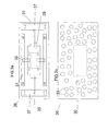
- FIGS. 3 a and 3 b are schematic front and rear plan view illustrations of a TEC unit, constructed and operative according to a preferred embodiment of the invention
- FIG. 4 is a schematic illustration of a power consumption profile for a TEC unit
- FIG. 5 is a block diagram illustration of a system for compensating for emissivity, according to one embodiment of the invention.
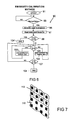
- FIG. 6 is a block diagram illustration of a method for compensating for emissivity, according to one embodiment of the invention.
- FIG. 7 is a schematic illustration of a plate in a system according to one embodiment of the present invention.
- the present invention relates to improvements devised for a thermal vision countermeasure system, which enables concealment of objects from identification by thermal imaging night vision systems and/or for deception of heat seeking missiles.
- the basic system is described in applicant's co-pending Israeli patent application no. 177368.
- the invention relates to the use of heat radiation to create equilibrium with the background radiation—hotter or cooler—in a plate screening an object to be camouflaged, by using controlled thermoelectric (Peltier effect) modules.
- the system also permits changing the observed heat signature of the object by generating a fake thermal signature for all or part of the object, so as to mislead a viewer. In this way, the target cannot be identified or classified, and a false battle situation awareness will be created.
- Activating the system according to the present invention will substantially reduce detection and view, in one case, or cause a mistake of target classification, in another case, depending on whether the user of the system selects a stealth or deception mode.
- the screen is formed of at least one, and preferably of a plurality of thermoelectric (TEC) units and a controller for controlling individually the temperature of the thermoelectric units. While the screen can be formed of a single TEC unit, utilizing a plurality of smaller units provides greater flexibility and ensures operation of most of the screen, even in the event that one or more TEC units are damaged or cease to function.
- the controller is coupled to a power source coupled to the TEC units. The controller causes the power source to provide a level of power to the thermoelectric unit so as to generate a selected temperature in at least part of the screen. It is a particular feature of the present invention that the plate is substantially larger in size than the TEC module that is controlling its temperature.
- a sensor for measuring the temperature of one side of the screen or thermoelectric unit and providing an indication thereof to the controller.
- the controller uses this temperature to adjust the temperature, and thus, the thermal signature, of the TEC unit.
- an additional thermal imaging sensor is provided which continuously measures the background temperature behind the object being protected (usually at the opposite side of the object from the viewer), even at long distance.
- the controller varies the level of power, based on the Peltier effect, in order to keep the surface temperature of the screen substantially equal to that of the background, even if the background is higher or lower than the ambient temperature.
- this embodiment can more completely confuse ATR systems and gunners using thermal vision systems.
- each thermoelectric cooling unit includes the following: a thermoelectric heating/cooling thereto electric cooler (TEC) connected to a power source, which controls the heating/cooling of the TEC surfaces and, consequently, of plates coupled to one of those surface.
- the TEC is coupled to a metal plate formed of aluminum or copper or both.
- the plate may have any desired geometric contour.
- the plate is substantially larger than the TEC (e.g., TEC surface area 60 ⁇ 60 mm, and metal plate area 220 ⁇ 220) and can be of various widths, preferably between about 2 to 5 mm. According to one embodiment, the plate is about 4 mm thick and therefore rigid and more suitable for military use.
- This plate with its TEC acts as one pixel, and several pixels like this can be mounted on a bigger plate to accommodate all of them together on same larger plate, as shown, for example, at 110 in FIG. 7 .
- an 880 ⁇ 880 plate can have a structure of 16 pixels of about 220 ⁇ 220 in a 4 ⁇ 4 matrix.
- Other structures can be made of a size that will be suitable to cover parts of the object to be protected.
- a plate of 880 ⁇ 220 could be formed of 4 pixels in a row.
- a number of smaller plates can be coupled to one another, as by screws.
- the ratio of TEC to plate surface area can be between 1:1 (i.e., the entire surface is covered with TECs, although this is more costly and will consume more power) to about 1:14 for optimum cost/performance, and up to about 1:44, when using copper plates and advanced structure combined with heat pipes, thereby reducing overall cost, complexity and power consumption and making the system practical.
- the TEC is positioned in the center of the plate.
- the TEC is further coupled to a heat sink that absorbs heat from the TEC, the heat sink being coupled to a fan which dissipates heat from the heat sink through convection.
- each such pixel can have a different temperature from its neighboring pixels.
- a “textured” thermal signature can be generated, which is substantially more realistic against a natural background than a signature of a single temperature.
- FIG. 1 a there is shown a schematic illustration of various parts of a TEC unit constructed and operative in accordance with one embodiment of the invention.
- the unit includes: a metal plate 1 , illustrated in “A” as being rectangular in shape, and in “B” as having curved edges, a TEC 2 , a heat sink 3 and a fan 4 .
- FIG. 1 b shows a schematic illustration of TEC unit 5 wherein: metal plate 1 is coupled to TEC 2 which is further coupled to heat sink 3 which dissipates heat using fan 4 .
- the process of cooling the outer side of plate 1 is as follows: heat is removed from the outer side of plate 1 by means of TEC 2 , the heat is then conducted to the inner side of TEC 2 , this heat is absorbed with heat sink 3 and then dissipated into the surrounding environment utilizing fan 4 .
- This process allows rapid cooling of plate 1 .
- the TEC will change the direction of heat flow, i.e.,—the cool side will become the hot side, and vice versa, so as to provide heating of plate 1 .
- the polarity and pulse width modulation power level are controlled by the CPU, preferably according to radiometric data from the thermal imaging sensor and video processor, using chip embedded algorithms for best adaptation to the background.
- FIG. 2 a and FIG. 2 b there are shown schematic illustrations of a TEC unit in relation to a surface that requires camouflage, constructed and operative in accordance with one embodiment of the invention.
- TEC unit 7 is coupled to surface 9 , preferably using shock absorbers 11 across an air gap 13 .
- air gap 13 is of dimensions so as to provide sufficient thermal insulation of the camouflaged surface, preferably a few millimeters to a few centimeters. This insulation prevents heat generated at the camouflaged surface from reaching metal plate 1 via convection and changing the temperature generated by the TEC.
- the back side of plate 1 may further include heat radiation insulators and reflectors 15 , to reduce the effect of heating of plate 1 by heat radiated from surface 9 .
- Shock absorbers 11 allow easy and safe coupling of the TEC unit to the camouflaged surface 9 .
- the shock absorbers allow the sensitive TEC unit a degree of freedom, protecting the unit when surface 9 is in motion or vibrating.
- the TEC unit is constructed so that the substantially smaller TEC can perform uniform cooling or heating over the entire surface of the plate (which is substantially larger).
- FIG. 3 a there are shown schematic illustrations of the back ( FIG. 3 a ), and front ( FIG. 3 b ) side of a TEC unit 31 .
- Metal plate 36 made of copper or aluminum, or a combination of both, that preferably is painted in the side facing outside, is drilled with a plurality of holes 33 , preferably of diameter between about 2-10 mm. The holes may be drilled in every location on the metal plate except for area 30 , which is directly above the TEC itself.
- the holes reduce the overall weight of the TEC unit, thus allowing more flexible use in various applications (in particular, applications in which the weight of the TEC ⁇ plate unit is a substantial parameter). It is a particular feature of this embodiment of the invention that holes which are sufficiently small are not seen from distances above 50 meters, or so, by conventional thermal imaging devices.
- the holes are drilled through about 90% of the thickness of the plate, so they do not penetrate to the side of the viewer. In this way, the weight of the plate can be reduced, and there will be no holes to be observed by one looking at the target. In addition, about 10% or more of the metal remains to conduct the heat.
- the holes are designed such that sand or dust will not fill them. In this way, the surface thermal flatness distribution is better.
- TEC 39 is bolted to aluminum plate 36 .
- One or more heat pipes 35 are coupled to aluminum plate 36 .
- a plurality of metal strips 37 are coupled to aluminum plate 36 .
- Strips 37 are thin copper strips, which can be, for example, about 20 on each pixel plate ⁇ TEC, which are positioned at, or near, the perimeter of plate 36 .
- the strips allow the plate to cool uniformly (the TEC may heat the plate using the same mechanism, cooling was given as an example only) on its entire surface.
- the ability to cool the surface uniformly improves the response time and efficiency of TEC unit 31 .
- the rapid and uniform heating and cooling is an important feature of the invention as it improves the reaction time of the camouflage plates.
- electrical power delivered to the TEC unit is controlled so to reduce the overall consumption of energy while retaining the TEC unit's ability to change temperature rapidly. It is a particular feature of the invention to provide the TEC unit with electrical current that is delivered in a specific pattern over configured periods of time. This pattern preferably is controlled by the CPU and embedded software. Referring to FIG. 4 , there is shown a schematic illustration of a power consumption profile for a TEC unit (not shown). Firstly, the TEC unit receives a high current power 41 , which causes the rapid heating (or cooling) of the TEC, leading to the heating of the TEC unit's surface ( 1 in FIG. 1 ).
- This rapid heating causes the temperature of the surface to pass the selected temperature (which may be determined according to programmed settings, see applicant's co-pending application, described above).
- the TEC unit receives high power. This period allows the plate to cool down and reach the pre-selected temperature.
- the TEC receives another current pulse 42 (smaller then pulse 41 ), which again, causes the temperature to rise slightly above the preset temperature. This process can be repeated (pulse 42 ′), thus maintaining the temperature substantially close to the preset temperature.
- This feature reduces the power consumption of the TEC unit, as it does not require high current to be provided all the time. Rather, once the plate reaches the preset temperature, the TEC only needs low power to maintain that temperature.
- This power pattern can also use the well-known PID formulation, for better accuracy.
- a system and method are provided for calibrating the TEC unit's radiated temperature to that of an ambient distant object.
- the system includes: a thermal radiation camera (e.g. thermal camera imaging, or an infrared temperature gun or any other compatible application for measuring temperature at a distance), means, such as a motor, for turning the camera, a TEC unit (or a plurality of units), all coupled to a decision making unit and video image processor that provides radiometric data to the CPU which controls all parts of the system.
- FIG. 5 there is shown a schematic illustration of a calibration system, constructed and operative according to one embodiment of the invention, for compensating for emissivity of a TEC unit (or units), so as to provide a thermal signature substantially the same as that of an ambient, distant object.
- the system includes: a temperature measuring unit 80 which includes: thermal camera 70 which is coupled to electrical rotating motor cam 72 and 68 , controlled by a controller 64 , and a temperature control unit 82 which includes: controller 64 (can be a processor (CPU), CPLD, or DSP circuit) coupled to control unit 68 and to camera 70 , further coupled to power unit 84 and to TEC unit 62 .
- controller 64 can be a processor (CPU), CPLD, or DSP circuit
- TEC unit 62 can be a single large plate, or can be a plurality of pixels, as described above. In this case, a single central CPU is coupled to, and coordinates operation of, all the TEC pixels. Alternatively, several CPU's or CPLD's can be utilized, each coupled to different groups of pixels.
- Camera 70 measures the temperature of distant object 60 with the aid of a video image processor with radiometric output, or by using a thermal camera with radiometric output, and provides an electrical signal corresponding thereto to controller 64 , which activates power unit 84 to heat TEC unit 62 to the measured temperature of object 60 .
- the electrical cam rotates camera 70 to position 86 .
- Camera 70 then proceeds to measure the actual observed temperature of TEC unit 62 and reports the information to controller 64 .
- Controller 64 compares the measured temperatures of object 60 and TEC unit 62 and adjusts the temperature of TEC unit 62 , by providing current through power unit 84 , so that the temperature radiated towards viewer 66 will be substantially equal to that of object 60 .
- a second, fixed thermal camera 85 is provided that looks at the TEC unit plate 62 at all times. While this eliminates the need for rotation of camera 70 from object to TEC, it is less preferred as two cameras will provide larger errors (since it is difficult to calibrate them the same).
- Algorithm 90 is one logical method for calibrating the thermal radiation emitted by TEC unit 62 (in FIG. 6 ) with that of object 60 (in FIG. 6 ). This algorithm is programmed into CPU 64 (in FIG. 6 ) in physical DSP circuitry or into memory.
- condition block 93 requires that the temperature of object 60 will equal that of TEC unit 62 (the temperature is measured directly from TEC unit 62 using a thermocouple or other means). If the temperatures are not equal the algorithm requires the system to check the temperature again. Once the temperatures are reported equal, an order block 95 , to rotate camera 70 to position 86 is given. Once this is done, a temperature readout is provided to CPU 64 in block 97 .
- Condition block 99 requires the temperature measured by camera 70 of TEC unit 62 , to equal that of the measured temperature of object 60 within a margin of ⁇ 0.1° C. If the temperatures are equal within this margin the algorithm ends [block 109 ′].
- condition block 101 determines if the camera measured temperature of TEC unit 62 is higher than that of object 60 . If this is the case, a correction is added to the temperature of TEC unit 62 via power unit 84 , lowering the TEC unit's temperature by the difference between the temperatures obtained from object 60 and the one obtained from the TEC unit 62 . (Preferably, both temperatures are obtained with the same camera). After this addition, condition block 101 is provided again.
- condition block 107 requires the temperatures that were substantially equilibrated to be equal within a margin of ⁇ 0.1° C. If the temperatures are equal within this margin, the algorithm ends [block 109 ]. If not, the algorithm returns to condition block 101 .
- this method compensates for emissive errors by correcting any differences in observed temperature between a background object and the plate. This result is then transferred to all the other plates protecting the object, so a large number of plates covering an object will all be accurately calibrated to the object behind the camouflaged object.
- the system is capable of working on the entire Infra Red Spectrum, and especially 7-14 ⁇ m and 3-5 ⁇ m bands.
- the plate is painted with the same paint and/or the same color as used on the object to be protected.
- a plurality of different signatures are created around the target object, each facing different directions.
- This embodiment provides protection for a target object from thermal seekers looking from different directions and angles.
- one set of TEC plates can be placed above the object, to protect against UAV or other identification from the air, while others are placed in front and on the sides of the target, to protect against a viewer or attacker from the side.
- the background viewed by a viewer will be different at each angle. Therefore, preferably thermal cameras or other sensors are aimed at the object from various angles, each providing the heat signature of the background it sees.
- the thermally controlled pixels provide the signature that preferably includes the texture of the background in each direction, according to the video imaging processor and CPU data. In this way, for example, a tank parked on asphalt in front of trees can be screened by TEC units creating the thermal signature of trees, when viewed from the side, and of asphalt, when viewed from above.
- TEC units can be used to generate multiple signatures when viewed from one angle.
- the left side of the object can project the thermal signature of the right side background and vice versa, or front and back can be interchanged, as desired.
Landscapes
- Engineering & Computer Science (AREA)
- General Engineering & Computer Science (AREA)
- Radiation Pyrometers (AREA)
- Photometry And Measurement Of Optical Pulse Characteristics (AREA)
- Investigating Or Analyzing Materials Using Thermal Means (AREA)
Applications Claiming Priority (3)
| Application Number | Priority Date | Filing Date | Title |
|---|---|---|---|
| IL186320A IL186320A (he) | 2007-09-25 | 2007-09-25 | מערכת הסתרה תרמית פעילה הניתנת להתאמה |
| IL186320 | 2007-09-25 | ||
| PCT/IL2008/001301 WO2009040823A2 (en) | 2007-09-25 | 2008-09-25 | Active adaptive thermal stealth system |
Related Parent Applications (1)
| Application Number | Title | Priority Date | Filing Date |
|---|---|---|---|
| PCT/IL2008/001301 A-371-Of-International WO2009040823A2 (en) | 2007-09-25 | 2008-09-25 | Active adaptive thermal stealth system |
Related Child Applications (1)
| Application Number | Title | Priority Date | Filing Date |
|---|---|---|---|
| US13/300,702 Continuation-In-Part US9179079B2 (en) | 2007-09-25 | 2011-11-21 | Active adaptive thermal stealth system |
Publications (2)
| Publication Number | Publication Date |
|---|---|
| US20100207025A1 US20100207025A1 (en) | 2010-08-19 |
| US8080792B2 true US8080792B2 (en) | 2011-12-20 |
Family
ID=40326283
Family Applications (1)
| Application Number | Title | Priority Date | Filing Date |
|---|---|---|---|
| US12/679,686 Expired - Fee Related US8080792B2 (en) | 2007-09-25 | 2008-09-25 | Active adaptive thermal stealth system |
Country Status (5)
| Country | Link |
|---|---|
| US (1) | US8080792B2 (he) |
| EP (1) | EP2212119B1 (he) |
| IL (1) | IL186320A (he) |
| PL (1) | PL2212119T3 (he) |
| WO (1) | WO2009040823A2 (he) |
Cited By (3)
| Publication number | Priority date | Publication date | Assignee | Title |
|---|---|---|---|---|
| US20120205560A1 (en) * | 2009-08-16 | 2012-08-16 | Eltics Ltd | Network centric system and method for active thermal stealth or deception |
| US20170322324A1 (en) * | 2016-05-03 | 2017-11-09 | General Electric Company | Temperature compensation for silicon photomultiplier based detector |
| RU2815116C1 (ru) * | 2023-03-10 | 2024-03-11 | Владимир Ильич Миронченко | Способ маскировки |
Families Citing this family (17)
| Publication number | Priority date | Publication date | Assignee | Title |
|---|---|---|---|---|
| US8403253B1 (en) | 2009-03-18 | 2013-03-26 | Israel Aerospace Industries Ltd. | Active IR signature target simulation system and a method thereof |
| US8909385B2 (en) | 2011-01-14 | 2014-12-09 | Alliant Techsystems Inc. | Infrared signature matching system, control circuit, and related method |
| SE536136C2 (sv) * | 2011-06-07 | 2013-05-28 | Bae Systems Haegglunds Ab | Anordning och metod för signaturanpassning |
| SE536137C2 (sv) | 2011-06-07 | 2013-05-28 | Bae Systems Haegglunds Ab | Anordning för signaturanpassning |
| CN103033089A (zh) * | 2012-12-14 | 2013-04-10 | 中国人民解放军总后勤部军需装备研究所 | 一种防红外隐身电子毯 |
| FR3005350B1 (fr) * | 2013-05-03 | 2015-04-17 | Nexter Systems | Procede et dispositif de masquage adaptatif. |
| CN103425080B (zh) * | 2013-06-24 | 2015-09-23 | 西安应用光学研究所 | 主动成像式红外隐身系统 |
| RU2582560C1 (ru) * | 2014-12-08 | 2016-04-27 | Федеральное государственное казенное военное образовательное учреждение высшего профессионального образования "Военный учебно-научный центр Военно-воздушных сил "Военно-воздушная академия имени профессора Н.Е. Жуковского и Ю.А. Гагарина" (г. Воронеж) Министерства обороны Российской Федерации | Способ имитации теплового контраста объекта |
| RU2666296C1 (ru) * | 2017-04-05 | 2018-09-06 | Федеральное государственное казенное военное образовательное учреждение высшего образования "Военный учебно-научный центр Военно-воздушных сил "Военно-воздушная академия имени профессора Н.Е. Жуковского и Ю.А. Гагарина" (г. Воронеж) Министерства обороны Российской Федерации | Устройство имитации теплового контраста объекта |
| CN107665624A (zh) * | 2017-10-30 | 2018-02-06 | 西南大学 | 一种恒温隐形、低温放大目标物体的直流幻觉装置 |
| RU2704927C1 (ru) * | 2019-02-12 | 2019-10-31 | Федеральное государственное казенное военное образовательное учреждение высшего образования "ВОЕННАЯ АКАДЕМИЯ МАТЕРИАЛЬНО-ТЕХНИЧЕСКОГО ОБЕСПЕЧЕНИЯ имени генерала армии А.В. Хрулева" | Мобильный эластичный резервуар-фальштент автомобильного средства заправки и транспортирования горючего военного назначения |
| RU201285U1 (ru) * | 2020-03-11 | 2020-12-08 | Акционерное общество "ОКБ-Планета" АО "ОКБ-Планета" | Комбинированная ложная цель |
| EP4012325A1 (en) | 2020-12-10 | 2022-06-15 | Centre de Recherches Métallurgiques ASBL - Centrum voor Research in de Metallurgie VZW | Multilayer ultrathin and flexible unit heater cells for infrared stealth |
| RU2765366C1 (ru) * | 2021-03-29 | 2022-01-28 | Федеральное государственное бюджетное учреждение "Центральный научно-исследовательский испытательный институт инженерных войск имени Героя Советского Союза генерал-лейтенанта инженерных войск Д.М. Карбышева" Министерства обороны Российской Федерации | Тепловой имитатор техники |
| CN114859710B (zh) * | 2022-04-14 | 2025-04-25 | 中国航发沈阳发动机研究所 | 一种航空发动机隐身信号特征控制方法 |
| US12175857B2 (en) * | 2022-12-30 | 2024-12-24 | Anton Zavoyskikh | Multipurpose non-visual wearable display |
| CN119343040B (zh) * | 2024-10-18 | 2025-10-10 | 华南理工大学 | 一种光热伪装器件及其制造方法 |
Citations (10)
| Publication number | Priority date | Publication date | Assignee | Title |
|---|---|---|---|---|
| US5117737A (en) * | 1990-11-01 | 1992-06-02 | Grumman Aerospace Corporation | Spectrally selective transparency for background thermal matching |
| JPH09296999A (ja) | 1996-05-02 | 1997-11-18 | Toshiba Corp | 飛翔体の特定部位認識装置 |
| US6144031A (en) | 1997-04-21 | 2000-11-07 | Inframetrics Inc. | Infrared video camera system with uncooled focal plane array and radiation shield |
| US6338292B1 (en) * | 1999-09-30 | 2002-01-15 | Robert Fisher Reynolds | Thermal and visual camouflage system |
| US20030097845A1 (en) * | 2001-11-26 | 2003-05-29 | John Saunders | Thermoelectric modules and a heating and cooling apparatus incorporating same |
| US20040213982A1 (en) * | 2002-12-16 | 2004-10-28 | Dr. Igor Touzov | Addressable camouflage for personnel, mobile equipment and installations |
| US20050045702A1 (en) | 2003-08-29 | 2005-03-03 | William Freeman | Thermoelectric modules and methods of manufacture |
| US20050052310A1 (en) * | 2003-09-10 | 2005-03-10 | Snaper Alvin A. | Adaptive modification of surface properties to alter the perception of its underlying structure |
| US7102814B1 (en) * | 2004-08-30 | 2006-09-05 | The United States Of America As Represented By The Secretary Of The Navy | Personal portable blankets as an infrared shielding device for field activities |
| US20070034774A1 (en) * | 2005-03-11 | 2007-02-15 | The Boeing Company | Active camouflage using real-time spectral matching |
Family Cites Families (1)
| Publication number | Priority date | Publication date | Assignee | Title |
|---|---|---|---|---|
| IL177368A (en) * | 2006-08-08 | 2011-06-30 | Eltics Ltd | Thermal vision and heat-seeking missile countermeasure system |
-
2007
- 2007-09-25 IL IL186320A patent/IL186320A/he active IP Right Grant
-
2008
- 2008-09-25 PL PL08808100T patent/PL2212119T3/pl unknown
- 2008-09-25 WO PCT/IL2008/001301 patent/WO2009040823A2/en not_active Ceased
- 2008-09-25 US US12/679,686 patent/US8080792B2/en not_active Expired - Fee Related
- 2008-09-25 EP EP08808100.5A patent/EP2212119B1/en not_active Not-in-force
Patent Citations (10)
| Publication number | Priority date | Publication date | Assignee | Title |
|---|---|---|---|---|
| US5117737A (en) * | 1990-11-01 | 1992-06-02 | Grumman Aerospace Corporation | Spectrally selective transparency for background thermal matching |
| JPH09296999A (ja) | 1996-05-02 | 1997-11-18 | Toshiba Corp | 飛翔体の特定部位認識装置 |
| US6144031A (en) | 1997-04-21 | 2000-11-07 | Inframetrics Inc. | Infrared video camera system with uncooled focal plane array and radiation shield |
| US6338292B1 (en) * | 1999-09-30 | 2002-01-15 | Robert Fisher Reynolds | Thermal and visual camouflage system |
| US20030097845A1 (en) * | 2001-11-26 | 2003-05-29 | John Saunders | Thermoelectric modules and a heating and cooling apparatus incorporating same |
| US20040213982A1 (en) * | 2002-12-16 | 2004-10-28 | Dr. Igor Touzov | Addressable camouflage for personnel, mobile equipment and installations |
| US20050045702A1 (en) | 2003-08-29 | 2005-03-03 | William Freeman | Thermoelectric modules and methods of manufacture |
| US20050052310A1 (en) * | 2003-09-10 | 2005-03-10 | Snaper Alvin A. | Adaptive modification of surface properties to alter the perception of its underlying structure |
| US7102814B1 (en) * | 2004-08-30 | 2006-09-05 | The United States Of America As Represented By The Secretary Of The Navy | Personal portable blankets as an infrared shielding device for field activities |
| US20070034774A1 (en) * | 2005-03-11 | 2007-02-15 | The Boeing Company | Active camouflage using real-time spectral matching |
Cited By (5)
| Publication number | Priority date | Publication date | Assignee | Title |
|---|---|---|---|---|
| US20120205560A1 (en) * | 2009-08-16 | 2012-08-16 | Eltics Ltd | Network centric system and method for active thermal stealth or deception |
| US8487254B2 (en) * | 2009-08-16 | 2013-07-16 | Eltics Ltd | Network centric system and method for active thermal stealth or deception |
| US20170322324A1 (en) * | 2016-05-03 | 2017-11-09 | General Electric Company | Temperature compensation for silicon photomultiplier based detector |
| US10564299B2 (en) * | 2016-05-03 | 2020-02-18 | General Electric Company | Temperature compensation for silicon photomultiplier based detector |
| RU2815116C1 (ru) * | 2023-03-10 | 2024-03-11 | Владимир Ильич Миронченко | Способ маскировки |
Also Published As
| Publication number | Publication date |
|---|---|
| WO2009040823A2 (en) | 2009-04-02 |
| US20100207025A1 (en) | 2010-08-19 |
| WO2009040823A3 (en) | 2010-03-04 |
| EP2212119A2 (en) | 2010-08-04 |
| IL186320A (he) | 2014-09-30 |
| PL2212119T3 (pl) | 2016-01-29 |
| EP2212119A4 (en) | 2012-03-07 |
| EP2212119B1 (en) | 2015-06-10 |
| IL186320A0 (en) | 2008-11-03 |
Similar Documents
| Publication | Publication Date | Title |
|---|---|---|
| US8080792B2 (en) | Active adaptive thermal stealth system | |
| US8013302B2 (en) | Thermal vision and heat seeking missile countermeasure system | |
| US9179079B2 (en) | Active adaptive thermal stealth system | |
| CA2457669C (en) | Autonomous weapon system | |
| US6338292B1 (en) | Thermal and visual camouflage system | |
| US7102814B1 (en) | Personal portable blankets as an infrared shielding device for field activities | |
| US5347910A (en) | Target acquisition system | |
| AU2002210260A1 (en) | Autonomous weapon system | |
| US20040061595A1 (en) | Commander's decision aid for combat ground vehicle integrated defensive aid suites | |
| US20020149510A1 (en) | Method and apparatus for the protection of mobile military facilities | |
| US20130099096A1 (en) | Flash detection and laser response system | |
| US11060822B2 (en) | Active multi-spectral system for generating camouflage or other radiating patterns from objects in an infrared scene | |
| RU2285888C2 (ru) | Способ защиты подвижного наземного объекта от обнаружения и поражения высокоточным оружием с инфракрасными головками самонаведения и экранирующее устройство для его реализации | |
| Kastek et al. | Concept of infrared sensor module for sniper detection system | |
| GB2274154A (en) | Modifying the infra-red appearance of a body | |
| GB2374222A (en) | Imaging and tracking apparatus | |
| US7880870B1 (en) | Linear array sensors for target detection including hydrocarbon events such as gun, mortar, RPG missile and artillery firings | |
| RU2829573C1 (ru) | Комплекс маскировки объекта | |
| Gilman | Infrared Detection Devices | |
| Smiljanic | UAV-based Detection of Landmines and Unexploded Ordnance (UXO) | |
| WO1996004520A1 (en) | Apparatus for altering the infrared characteristics of a body | |
| US7551781B1 (en) | Active matrix acquisition and targeting system | |
| RU2704549C1 (ru) | Устройство защиты от самонаводящихся суббоеприпасов | |
| Moore et al. | Counter sniper: a small projectile and gunfire localization system | |
| O'Keefe et al. | Infrared and visible combat identification marking materials |
Legal Events
| Date | Code | Title | Description |
|---|---|---|---|
| ZAAA | Notice of allowance and fees due |
Free format text: ORIGINAL CODE: NOA |
|
| ZAAB | Notice of allowance mailed |
Free format text: ORIGINAL CODE: MN/=. |
|
| STCF | Information on status: patent grant |
Free format text: PATENTED CASE |
|
| FPAY | Fee payment |
Year of fee payment: 4 |
|
| MAFP | Maintenance fee payment |
Free format text: PAYMENT OF MAINTENANCE FEE, 8TH YR, SMALL ENTITY (ORIGINAL EVENT CODE: M2552); ENTITY STATUS OF PATENT OWNER: SMALL ENTITY Year of fee payment: 8 |
|
| FEPP | Fee payment procedure |
Free format text: MAINTENANCE FEE REMINDER MAILED (ORIGINAL EVENT CODE: REM.); ENTITY STATUS OF PATENT OWNER: SMALL ENTITY |
|
| LAPS | Lapse for failure to pay maintenance fees |
Free format text: PATENT EXPIRED FOR FAILURE TO PAY MAINTENANCE FEES (ORIGINAL EVENT CODE: EXP.); ENTITY STATUS OF PATENT OWNER: SMALL ENTITY |
|
| STCH | Information on status: patent discontinuation |
Free format text: PATENT EXPIRED DUE TO NONPAYMENT OF MAINTENANCE FEES UNDER 37 CFR 1.362 |
|
| FP | Lapsed due to failure to pay maintenance fee |
Effective date: 20231220 |