US8080412B2 - Multiwell incubation apparatus and method of analysis using the same - Google Patents
Multiwell incubation apparatus and method of analysis using the same Download PDFInfo
- Publication number
- US8080412B2 US8080412B2 US12/297,011 US29701107A US8080412B2 US 8080412 B2 US8080412 B2 US 8080412B2 US 29701107 A US29701107 A US 29701107A US 8080412 B2 US8080412 B2 US 8080412B2
- Authority
- US
- United States
- Prior art keywords
- wells
- well
- temperature
- housing vessel
- incubation apparatus
- Prior art date
- Legal status (The legal status is an assumption and is not a legal conclusion. Google has not performed a legal analysis and makes no representation as to the accuracy of the status listed.)
- Expired - Fee Related, expires
Links
- 238000011534 incubation Methods 0.000 title claims abstract description 114
- 238000004458 analytical method Methods 0.000 title claims description 21
- 239000007788 liquid Substances 0.000 claims abstract description 50
- 229920006395 saturated elastomer Polymers 0.000 claims abstract description 18
- 239000004020 conductor Substances 0.000 claims abstract description 9
- 239000007789 gas Substances 0.000 claims description 37
- QVGXLLKOCUKJST-UHFFFAOYSA-N atomic oxygen Chemical compound [O] QVGXLLKOCUKJST-UHFFFAOYSA-N 0.000 claims description 11
- 239000001301 oxygen Substances 0.000 claims description 11
- 229910052760 oxygen Inorganic materials 0.000 claims description 11
- 238000000034 method Methods 0.000 claims description 5
- 239000011148 porous material Substances 0.000 claims description 5
- 230000001678 irradiating effect Effects 0.000 claims description 4
- 238000009630 liquid culture Methods 0.000 claims description 4
- 238000006243 chemical reaction Methods 0.000 claims description 3
- 238000002156 mixing Methods 0.000 claims description 3
- 230000003287 optical effect Effects 0.000 claims description 2
- 239000000126 substance Substances 0.000 claims description 2
- 241000700605 Viruses Species 0.000 claims 1
- 238000009833 condensation Methods 0.000 abstract description 6
- 230000005494 condensation Effects 0.000 abstract description 6
- 239000012530 fluid Substances 0.000 description 10
- XLYOFNOQVPJJNP-UHFFFAOYSA-N water Substances O XLYOFNOQVPJJNP-UHFFFAOYSA-N 0.000 description 9
- 241000588724 Escherichia coli Species 0.000 description 6
- 229910052782 aluminium Inorganic materials 0.000 description 6
- XAGFODPZIPBFFR-UHFFFAOYSA-N aluminium Chemical compound [Al] XAGFODPZIPBFFR-UHFFFAOYSA-N 0.000 description 6
- 238000012258 culturing Methods 0.000 description 6
- 238000005259 measurement Methods 0.000 description 6
- 230000001105 regulatory effect Effects 0.000 description 6
- 238000002474 experimental method Methods 0.000 description 5
- 238000010438 heat treatment Methods 0.000 description 5
- 239000007787 solid Substances 0.000 description 5
- XKRFYHLGVUSROY-UHFFFAOYSA-N Argon Chemical compound [Ar] XKRFYHLGVUSROY-UHFFFAOYSA-N 0.000 description 4
- 238000010586 diagram Methods 0.000 description 4
- IJGRMHOSHXDMSA-UHFFFAOYSA-N Atomic nitrogen Chemical compound N#N IJGRMHOSHXDMSA-UHFFFAOYSA-N 0.000 description 3
- 229910001873 dinitrogen Inorganic materials 0.000 description 3
- 244000005700 microbiome Species 0.000 description 3
- 238000002835 absorbance Methods 0.000 description 2
- 238000013459 approach Methods 0.000 description 2
- 229910052786 argon Inorganic materials 0.000 description 2
- 230000033228 biological regulation Effects 0.000 description 2
- 238000004891 communication Methods 0.000 description 2
- 230000000694 effects Effects 0.000 description 2
- 238000001704 evaporation Methods 0.000 description 2
- 230000008020 evaporation Effects 0.000 description 2
- 239000000463 material Substances 0.000 description 2
- 230000035755 proliferation Effects 0.000 description 2
- 241000894007 species Species 0.000 description 2
- 230000006641 stabilisation Effects 0.000 description 2
- 238000011105 stabilization Methods 0.000 description 2
- 229910001220 stainless steel Inorganic materials 0.000 description 2
- 239000010935 stainless steel Substances 0.000 description 2
- 229920001817 Agar Polymers 0.000 description 1
- 241000894006 Bacteria Species 0.000 description 1
- 229910001369 Brass Inorganic materials 0.000 description 1
- RYGMFSIKBFXOCR-UHFFFAOYSA-N Copper Chemical compound [Cu] RYGMFSIKBFXOCR-UHFFFAOYSA-N 0.000 description 1
- 230000004308 accommodation Effects 0.000 description 1
- 239000008272 agar Substances 0.000 description 1
- 238000003491 array Methods 0.000 description 1
- 230000009286 beneficial effect Effects 0.000 description 1
- 230000005540 biological transmission Effects 0.000 description 1
- 239000010951 brass Substances 0.000 description 1
- 238000011109 contamination Methods 0.000 description 1
- 229910052802 copper Inorganic materials 0.000 description 1
- 239000010949 copper Substances 0.000 description 1
- 238000012937 correction Methods 0.000 description 1
- 238000013461 design Methods 0.000 description 1
- 238000009792 diffusion process Methods 0.000 description 1
- 238000010790 dilution Methods 0.000 description 1
- 239000012895 dilution Substances 0.000 description 1
- 239000011521 glass Substances 0.000 description 1
- 239000011810 insulating material Substances 0.000 description 1
- 238000000691 measurement method Methods 0.000 description 1
- 229910052751 metal Inorganic materials 0.000 description 1
- 239000002184 metal Substances 0.000 description 1
- 230000000813 microbial effect Effects 0.000 description 1
- 230000000149 penetrating effect Effects 0.000 description 1
- 229920003023 plastic Polymers 0.000 description 1
- 238000012545 processing Methods 0.000 description 1
- 230000002035 prolonged effect Effects 0.000 description 1
- 230000000306 recurrent effect Effects 0.000 description 1
- 238000004062 sedimentation Methods 0.000 description 1
- 239000000243 solution Substances 0.000 description 1
- 230000001954 sterilising effect Effects 0.000 description 1
- 238000004659 sterilization and disinfection Methods 0.000 description 1
- 239000000725 suspension Substances 0.000 description 1
- 238000012360 testing method Methods 0.000 description 1
- 238000012546 transfer Methods 0.000 description 1
- 238000009281 ultraviolet germicidal irradiation Methods 0.000 description 1
Images


Classifications
-
- C—CHEMISTRY; METALLURGY
- C12—BIOCHEMISTRY; BEER; SPIRITS; WINE; VINEGAR; MICROBIOLOGY; ENZYMOLOGY; MUTATION OR GENETIC ENGINEERING
- C12M—APPARATUS FOR ENZYMOLOGY OR MICROBIOLOGY; APPARATUS FOR CULTURING MICROORGANISMS FOR PRODUCING BIOMASS, FOR GROWING CELLS OR FOR OBTAINING FERMENTATION OR METABOLIC PRODUCTS, i.e. BIOREACTORS OR FERMENTERS
- C12M27/00—Means for mixing, agitating or circulating fluids in the vessel
- C12M27/16—Vibrating; Shaking; Tilting
-
- C—CHEMISTRY; METALLURGY
- C12—BIOCHEMISTRY; BEER; SPIRITS; WINE; VINEGAR; MICROBIOLOGY; ENZYMOLOGY; MUTATION OR GENETIC ENGINEERING
- C12M—APPARATUS FOR ENZYMOLOGY OR MICROBIOLOGY; APPARATUS FOR CULTURING MICROORGANISMS FOR PRODUCING BIOMASS, FOR GROWING CELLS OR FOR OBTAINING FERMENTATION OR METABOLIC PRODUCTS, i.e. BIOREACTORS OR FERMENTERS
- C12M1/00—Apparatus for enzymology or microbiology
- C12M1/16—Apparatus for enzymology or microbiology containing, or adapted to contain, solid media
- C12M1/18—Multiple fields or compartments
-
- B—PERFORMING OPERATIONS; TRANSPORTING
- B01—PHYSICAL OR CHEMICAL PROCESSES OR APPARATUS IN GENERAL
- B01F—MIXING, e.g. DISSOLVING, EMULSIFYING OR DISPERSING
- B01F31/00—Mixers with shaking, oscillating, or vibrating mechanisms
- B01F31/20—Mixing the contents of independent containers, e.g. test tubes
- B01F31/23—Mixing the contents of independent containers, e.g. test tubes by pivoting the containers about an axis
-
- B—PERFORMING OPERATIONS; TRANSPORTING
- B01—PHYSICAL OR CHEMICAL PROCESSES OR APPARATUS IN GENERAL
- B01L—CHEMICAL OR PHYSICAL LABORATORY APPARATUS FOR GENERAL USE
- B01L7/00—Heating or cooling apparatus; Heat insulating devices
- B01L7/54—Heating or cooling apparatus; Heat insulating devices using spatial temperature gradients
-
- C—CHEMISTRY; METALLURGY
- C12—BIOCHEMISTRY; BEER; SPIRITS; WINE; VINEGAR; MICROBIOLOGY; ENZYMOLOGY; MUTATION OR GENETIC ENGINEERING
- C12M—APPARATUS FOR ENZYMOLOGY OR MICROBIOLOGY; APPARATUS FOR CULTURING MICROORGANISMS FOR PRODUCING BIOMASS, FOR GROWING CELLS OR FOR OBTAINING FERMENTATION OR METABOLIC PRODUCTS, i.e. BIOREACTORS OR FERMENTERS
- C12M1/00—Apparatus for enzymology or microbiology
- C12M1/34—Measuring or testing with condition measuring or sensing means, e.g. colony counters
-
- C—CHEMISTRY; METALLURGY
- C12—BIOCHEMISTRY; BEER; SPIRITS; WINE; VINEGAR; MICROBIOLOGY; ENZYMOLOGY; MUTATION OR GENETIC ENGINEERING
- C12M—APPARATUS FOR ENZYMOLOGY OR MICROBIOLOGY; APPARATUS FOR CULTURING MICROORGANISMS FOR PRODUCING BIOMASS, FOR GROWING CELLS OR FOR OBTAINING FERMENTATION OR METABOLIC PRODUCTS, i.e. BIOREACTORS OR FERMENTERS
- C12M23/00—Constructional details, e.g. recesses, hinges
- C12M23/02—Form or structure of the vessel
- C12M23/12—Well or multiwell plates
-
- C—CHEMISTRY; METALLURGY
- C12—BIOCHEMISTRY; BEER; SPIRITS; WINE; VINEGAR; MICROBIOLOGY; ENZYMOLOGY; MUTATION OR GENETIC ENGINEERING
- C12M—APPARATUS FOR ENZYMOLOGY OR MICROBIOLOGY; APPARATUS FOR CULTURING MICROORGANISMS FOR PRODUCING BIOMASS, FOR GROWING CELLS OR FOR OBTAINING FERMENTATION OR METABOLIC PRODUCTS, i.e. BIOREACTORS OR FERMENTERS
- C12M37/00—Means for sterilizing, maintaining sterile conditions or avoiding chemical or biological contamination
-
- C—CHEMISTRY; METALLURGY
- C12—BIOCHEMISTRY; BEER; SPIRITS; WINE; VINEGAR; MICROBIOLOGY; ENZYMOLOGY; MUTATION OR GENETIC ENGINEERING
- C12M—APPARATUS FOR ENZYMOLOGY OR MICROBIOLOGY; APPARATUS FOR CULTURING MICROORGANISMS FOR PRODUCING BIOMASS, FOR GROWING CELLS OR FOR OBTAINING FERMENTATION OR METABOLIC PRODUCTS, i.e. BIOREACTORS OR FERMENTERS
- C12M41/00—Means for regulation, monitoring, measurement or control, e.g. flow regulation
- C12M41/12—Means for regulation, monitoring, measurement or control, e.g. flow regulation of temperature
- C12M41/14—Incubators; Climatic chambers
-
- C—CHEMISTRY; METALLURGY
- C12—BIOCHEMISTRY; BEER; SPIRITS; WINE; VINEGAR; MICROBIOLOGY; ENZYMOLOGY; MUTATION OR GENETIC ENGINEERING
- C12N—MICROORGANISMS OR ENZYMES; COMPOSITIONS THEREOF; PROPAGATING, PRESERVING, OR MAINTAINING MICROORGANISMS; MUTATION OR GENETIC ENGINEERING; CULTURE MEDIA
- C12N1/00—Microorganisms, e.g. protozoa; Compositions thereof; Processes of propagating, maintaining or preserving microorganisms or compositions thereof; Processes of preparing or isolating a composition containing a microorganism; Culture media therefor
-
- C—CHEMISTRY; METALLURGY
- C12—BIOCHEMISTRY; BEER; SPIRITS; WINE; VINEGAR; MICROBIOLOGY; ENZYMOLOGY; MUTATION OR GENETIC ENGINEERING
- C12Q—MEASURING OR TESTING PROCESSES INVOLVING ENZYMES, NUCLEIC ACIDS OR MICROORGANISMS; COMPOSITIONS OR TEST PAPERS THEREFOR; PROCESSES OF PREPARING SUCH COMPOSITIONS; CONDITION-RESPONSIVE CONTROL IN MICROBIOLOGICAL OR ENZYMOLOGICAL PROCESSES
- C12Q1/00—Measuring or testing processes involving enzymes, nucleic acids or microorganisms; Compositions therefor; Processes of preparing such compositions
- C12Q1/02—Measuring or testing processes involving enzymes, nucleic acids or microorganisms; Compositions therefor; Processes of preparing such compositions involving viable microorganisms
-
- B—PERFORMING OPERATIONS; TRANSPORTING
- B01—PHYSICAL OR CHEMICAL PROCESSES OR APPARATUS IN GENERAL
- B01L—CHEMICAL OR PHYSICAL LABORATORY APPARATUS FOR GENERAL USE
- B01L2300/00—Additional constructional details
- B01L2300/06—Auxiliary integrated devices, integrated components
- B01L2300/0627—Sensor or part of a sensor is integrated
- B01L2300/0654—Lenses; Optical fibres
-
- B—PERFORMING OPERATIONS; TRANSPORTING
- B01—PHYSICAL OR CHEMICAL PROCESSES OR APPARATUS IN GENERAL
- B01L—CHEMICAL OR PHYSICAL LABORATORY APPARATUS FOR GENERAL USE
- B01L2300/00—Additional constructional details
- B01L2300/08—Geometry, shape and general structure
- B01L2300/0809—Geometry, shape and general structure rectangular shaped
- B01L2300/0829—Multi-well plates; Microtitration plates
-
- B—PERFORMING OPERATIONS; TRANSPORTING
- B01—PHYSICAL OR CHEMICAL PROCESSES OR APPARATUS IN GENERAL
- B01L—CHEMICAL OR PHYSICAL LABORATORY APPARATUS FOR GENERAL USE
- B01L2300/00—Additional constructional details
- B01L2300/18—Means for temperature control
- B01L2300/1838—Means for temperature control using fluid heat transfer medium
- B01L2300/185—Means for temperature control using fluid heat transfer medium using a liquid as fluid
-
- B—PERFORMING OPERATIONS; TRANSPORTING
- B01—PHYSICAL OR CHEMICAL PROCESSES OR APPARATUS IN GENERAL
- B01L—CHEMICAL OR PHYSICAL LABORATORY APPARATUS FOR GENERAL USE
- B01L2300/00—Additional constructional details
- B01L2300/18—Means for temperature control
- B01L2300/1883—Means for temperature control using thermal insulation
-
- B—PERFORMING OPERATIONS; TRANSPORTING
- B01—PHYSICAL OR CHEMICAL PROCESSES OR APPARATUS IN GENERAL
- B01L—CHEMICAL OR PHYSICAL LABORATORY APPARATUS FOR GENERAL USE
- B01L3/00—Containers or dishes for laboratory use, e.g. laboratory glassware; Droppers
- B01L3/50—Containers for the purpose of retaining a material to be analysed, e.g. test tubes
- B01L3/508—Containers for the purpose of retaining a material to be analysed, e.g. test tubes rigid containers not provided for above
- B01L3/5085—Containers for the purpose of retaining a material to be analysed, e.g. test tubes rigid containers not provided for above for multiple samples, e.g. microtitration plates
- B01L3/50853—Containers for the purpose of retaining a material to be analysed, e.g. test tubes rigid containers not provided for above for multiple samples, e.g. microtitration plates with covers or lids
Definitions
- the present invention relates to a multiwell incubation apparatus which provides, in a single apparatus, a plurality of different incubation temperatures within a predetermined temperature range, and to a method of analysis using such an apparatus.
- Analyses using microbial cells or other biological specimens have been performed, for example, by inoculating microbes on an agar medium and observing them by the naked eye after they are maintained for a certain period of time at a constant temperature in an incubator.
- liquid culture has become more popular, which employs a multiwell plate having a plurality of wells.
- multiwell plates are often used to perform analysis of many specimens.
- liquid culture and specimen analyses are performed as follows: Specimens are added to the wells of a multiwell plate and cultured while maintained at a predetermined temperature for a predetermined period of time, followed by irradiation with light. Subsequently, transmitted light or scattering light including fluorescence is measured.
- the plate is typically placed on a flat heat-retentive plate.
- an incubation apparatus having shelves provided with such heat-retentive plates is employed (see Patent Document 1).
- the multiwell plates must be taken out of the incubation apparatuses, which is also inconvenient.
- Such continuous temperature-gradient incubation apparatuses have encountered a new problem caused by gas exchange occurring in the temperature gradient. That is, vapor generated from the liquid on the high-temperature side moves to the low-temperature side and condenses. More specifically, condensation occurring on the low-temperature side produces water droplets within the wells, leading to not only dilution of the test specimen to change the culture conditions but also overflow of the liquid. Thus, those temperature-gradient incubation apparatuses could not be applied to practical use.
- an object of the present invention is to provide a simultaneous multi-temperature incubation apparatus which, in a single apparatus, allows a plurality of temperature settings and requires no work for transferring the wells, wherein the problems caused by travel of liquid vapor and condensation into liquid are solved by regulation of the vapor pressure.
- a plurality of wells are arranged in rows and housed in a heat-conductive-material made container, one end of which is set at a high temperature and the other end is set at a low temperature; well rows are separated in terms of temperature so as to prevent gas communication therebetween; and each row of wells is provided with a liquid or gas flow channel or bath for regulating vapor pressure, to thereby achieve a uniform temperature prevailing within each row of wells and to allow positive compensation to be effected against any change in liquid volume which would otherwise be caused by the transfer of liquid vapor.
- the continuous temperature gradient is replaced by a plurality of temperatures with predetermined temperature differences, and a measurement is performed for those temperatures simultaneously.
- the inventors have found that, if light emitted through observation light paths provided for each row is scanned two-dimensionally, extra work for removing the wells before analysis is no longer required, to thereby achieve the present invention.
- the present invention provides a multiwell incubation apparatus having a well-housing vessel made of a heat conducting material and, detachably housed therein, wells for storing liquid, the wells being arranged in transverse rows and longitudinal rows, the multiwell incubation apparatus being also provided with a liquid or gas flow channel or bath for supply of a gas saturated with vapor of the liquid, the multiwell incubation apparatus being capable of maintaining incubation temperatures differing between individual transverse rows of wells with a predetermined temperature difference, so that the temperatures realize a temperature series which forms a predetermined temperature difference profile along the longitudinal rows, characterized in that the multiwell incubation apparatus includes a heat source for realizing the lowest temperature of the given temperature series, the heat source being disposed outside the well rows and along the transversely lined up wells close to a first side of the housing vessel; another heat source for realizing a temperature which is the highest in the given temperature series, the heat source being disposed outside the well rows and along a side opposite to the first side; and a
- the present invention also provides the multiwell incubation apparatus as described above, which further includes, in addition to the liquid or gas flow channel or bath for supply of a gas saturated with vapor of the liquid, separators disposed within a transverse row of a certain uniform temperature, so that changes in oxygen partial pressure or in partial pressure of a specific gas are realized in a staircase-like pattern within that row.
- the present invention provides an incubation method performed through use of the multiwell incubation apparatus as described above, which method comprises: adding specimens to the wells of the apparatus; and achieving, by use of the heat source along the first side of the well-housing vessel, a temperature which is the lowest within a predetermined temperature series, and also achieving, by use of the other heat source along the side opposite to the first side, a temperature which is the highest within the predetermined temperature series, to thereby realize incubation temperatures differing between individual transverse rows of wells, with a predetermined temperature difference.
- the present invention provides a method of analysis of specimens, performed through use of the multiwell incubation apparatus as described above, characterized by: performing incubation of specimens through adding specimens to the wells of the apparatus, achieving, by use of the heat source along the first side of the well-housing vessel, a temperature which is the lowest within a predetermined temperature series, and also achieving, by use of the other heat source along the side opposite to the first side, a temperature which is the highest within the predetermined temperature series, to thereby realize incubation temperatures differing between individual transverse rows of wells, with a predetermined temperature difference; and irradiating the specimens contained in the wells with light, and measuring light transmitted through the specimens or scattered light including fluorescence.
- the incubation apparatus With the incubation apparatus according to the present invention, a temperature series of equal intervals can be provided between the highest temperature and a temperature which is the lowest in a predetermined temperature range. Therefore, in a single run of incubation, several hundreds of experiments can be performed. Moreover, the user does not need to move the incubation apparatus before carrying out an analysis. In addition, since the problem of water evaporation from wells on the high temperature side and condensation on the low temperature side is eliminated, temperature-gradient culturing can be continued for a prolonged period of time, with small volumes of specimens. Therefore, the apparatus size can be reduced, and in addition, stacking of a number of such apparatus one on another enables the user to analyze the specimens under thousands of different conditions simultaneously.
- liquid or gas flow channel or bath is provided for each well row with an aim to regulate vapor pressure, a uniform temperature can be realized within a transverse row.
- oxygen partial pressure in a well can be regulated, and likewise, partial pressure of a specific gas can be easily modified so as to provide a plurality of partial pressure conditions.
- the incubation apparatus enables culturing of microbes under different temperature conditions, which has previously been difficult, enables the user to find optimal culture temperatures, and realizes proliferation of microorganisms whose temperature conditions are unknown.
- FIG. 1 A perspective view of an exemplary incubation apparatus according to the present invention.
- FIG. 2 A perspective view showing a portion of an incubation apparatus which is an embodiment of the present invention.
- FIG. 3 A perspective view showing another portion of the incubation apparatus.
- FIG. 4 A perspective view showing yet another portion of the incubation apparatus.
- FIG. 5 A perspective view showing a well-bearing portion to be incorporated into the incubation apparatus.
- FIG. 6 A cross section showing one state of accommodation attained by the incubation apparatus.
- FIG. 7 A perspective view of the incubation apparatus.
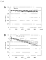
- FIG. 8 Growth curves obtained by use of the incubation apparatus.
- FIG. 9 Growth rates obtained by use of the incubation apparatus.
- FIG. 10 A cross section view of an exemplary incubation apparatus according to the present invention.
- FIG. 11 A perspective view of an exemplary shaker of an incubation apparatus according to the present invention.
- FIG. 12 A diagram showing an exemplary flow channel or bath of an incubation apparatus according to the present invention.
- FIG. 13 A diagram showing another exemplary flow channel or bath of an incubation apparatus according to the present invention.
- FIG. 14 A diagram showing yet another exemplary flow channel or bath of an incubation apparatus according to the present invention.
- FIG. 15 A diagram showing yet another exemplary flow channel or bath of an incubation apparatus according to the present invention.
- the present invention provides a multiwell incubation apparatus having a well-housing vessel made of a heat conducting material and, detachably housed therein, wells for storing liquid, the wells being arranged in transverse rows and longitudinal rows, the multiwell incubation apparatus being also provided with a liquid or gas flow channel or bath for supply of a gas saturated with vapor of the liquid, the channel or bath being disposed along a transverse row having a certain temperature, the multiwell incubation apparatus being capable of maintaining incubation temperatures differing between individual transverse rows of wells with a predetermined temperature difference, so that the temperatures realize a temperature series which forms a predetermined temperature difference profile along the longitudinal rows, characterized in that the multiwell incubation apparatus includes a heat source for realizing a temperature which is the lowest in the given temperature series, the heat source being disposed outside the well rows and along the transversely lined up wells close to a first side of the housing vessel; another heat source for realizing a temperature which is the highest in the given temperature series, the heat source
- the well-housing vessel of the incubation apparatus of the present invention should be made of heat conducting material in order to realize a plurality of different incubation temperatures.
- heat conducting materials metal is preferred because it allows a broad range of processing. Specifically, aluminum, stainless steel, brass, copper, and the like are preferred, wherein aluminum and stainless steel are more preferred.
- wells which are arranged in transverse rows and longitudinal rows are detachably housed. To this end, recesses are provided for receiving the wells.
- multi-well-accommodating recesses each of which accommodates a well unit in which several wells are aligned and connected to each other, are preferred for attaining a uniform incubation temperature for each transverse row. That is, in a preferred embodiment of the housing vessel, as shown in FIGS. 3 and 4 in which water of different but constant temperatures are circulated as heat sources, there are provided a plurality of rows of recesses, each configured to receive a well unit in which several wells are aligned and connected to each other.
- the heat conducting material has a profile of recurrent pattern. As a result, this facilitates provision of an incubation temperature series in the longitudinal direction of the heat conducting material.
- the socket of the well receiving portion preferably has such a depth that attains complete containment of a well excepting the upper portion thereof.
- the temperature of the upper portion of the well is equal to or higher than the temperature of the well receiving portion.
- the well is preferably made of a heat insulating material so that the temperature of the well is not affected.
- the number of the wells, arranged in transverse rows and longitudinal rows, in the incubation apparatus of the present invention can be determined as desired according to needs.
- a transverse ⁇ longitudinal well array of 8 ⁇ 12, 8 ⁇ 20, 16 ⁇ 20, or 18 ⁇ 24 may be feasible.
- wells are detachably housed in recesses of the mentioned housing vessel, with several transverse wells being connected to form a single body, as in FIGS. 3 and 4 .
- the wells are detachable individually or by well unit composed of several wells.
- the wells are preferably made of a transparent plastic material, glass, or a similar material in order to obtain light paths required for performing photometric observation.
- the incubation apparatus of the present invention has include, outside the well rows and along the transversely lined up wells close to a first side of the housing vessel, a heating device for attaining a temperature which is the lowest in the aforementioned predetermined temperature range or a flow channel allowing to pass a fluid of the lowest temperature therethrough; and also include, outside the well rows and along a side opposite to the first side, a heating device for attaining a temperature which is the highest in the mentioned predetermined temperature range or another flow channel allowing to pass a fluid of the highest temperature therethrough. For example, as shown in FIG.
- the transverse rows of wells which are present between the flow channel 2 and the flow channel 3 , attain a series of incubation temperatures among them between the lowest and the highest temperatures.
- the fluid may be gas or liquid, with liquid being preferred and water (or hot water) being more preferred.
- the main body ( 1 ) may be equipped with solid heating devices 18 , 19 as shown in FIG. 10 .
- the solid heating device include a heater and a Peltier element.
- a bridge portion like the one shown in FIG. 10 by reference numeral 16 , is preferably placed between each heat source and a corresponding recess wall of the housing vessel.
- provision of heat pipes 17 is also preferred.
- FIG. 10 shows such an example of housing vessel ( 1 ) having a lid ( 11 ) attached thereto.
- the incubation apparatus of the present invention further includes a liquid or gas flow channel or bath along a transverse row of a certain uniform temperature for regulating the vapor pressure or the oxygen partial pressure above the wells belonging to the transverse row, and also includes a separator for every row of a certain uniform temperature, whereby the saturated vapor pressure of the liquid at that temperature can be maintained.
- vapor is prevented from moving to other wells in the longitudinal direction, to thereby solve the problem that water evaporated from specimens on the high-temperature side condenses to form dew on the low-temperature side.
- the mentioned bath may be a porous material which has been impregnated with liquid.
- oxygen partial pressure can be regulated by exposing one end of the well row which is a regulation target of oxygen partial pressure and supplying argon gas or nitrogen gas through a flow channel on the other side. This allows a user to find optimal oxygen partial pressure conditions in culturing an unknown microbe.
- culture conditions in which oxygen partial pressure differs for each longitudinal row culturing can be performed under different conditions in terms of temperature and oxygen partial pressure simultaneously.
- oxygen is replaced by other species of gas, an atmosphere which brings about a different chemical reaction can be realized within a row of uniform temperature.
- the incubation apparatus preferably has a lid thereon so that all the wells are covered thereby.
- the lid is useful for maintaining stable temperatures, preventing evaporation of liquid in wells and contamination with saprophytic bacteria, or for regulating vapor pressure or oxygen partial pressure.
- the lid is equipped with a heat source along a first side thereof for realizing a temperature which is the lowest in a given temperature series and another heat source for realizing a temperature which is the highest in the given temperature series, the heat source being disposed outside the well rows and along a side opposite to the first side, temperature can be stabilized even more reliably.
- a middle tray may be provided between the housing vessel and the lid, and the middle tray may also be equipped with a heat source along a first side thereof for realizing a temperature which is the lowest in a given temperature series and another heat source for realizing a temperature which is the highest in the given temperature series, the heat source being disposed outside the well rows and along a side opposite to the first side.
- the middle tray may be formed as one section of the housing vessel.
- each hole having a diameter smaller than that of the wells the specimens can be visually observed. Also, through irradiation with light, any changes in absorbance, and scattering light including fluorescence can be measured. Alternatively, similar photometric observation is possible by providing, either above or below the respective wells, well observation holes which have a diameter smaller than that of the wells and a mirror for reflecting light for enabling optical observation or a light source.
- a UV irradiation device is additionally provided such that, upon opening of the lid, UV rays are applied to the lid and also to the recesses of the housing vessel where wells are accommodated, germ sterilization can be performed before and after incubation.
- the apparatus of the present invention may further include a shaker.
- the shaker may, for example, periodically tilt, by means of a lever 24 , the entire body of a housing vessel and a middle tray to which a lid has been attached, or a stack 1 of a number of such entire bodies, the lever being linked with a cam 23 rotated through a decelerator 22 driven by a motor 21 ( FIG. 11 ).
- the apparatus of the present invention is employed, and incubation is performed under creation of a predetermined temperature series in which different incubation temperatures, in a staircase pattern, are realized so that one temperature is assigned to one transverse row of wells.
- an incubation temperature gradient having a predetermined temperature series can be obtained, allowing compensation of liquid vapor pressure, to thereby enable handling of solutions or suspensions having a volume of less than some hundreds of microliters.
- an incubation of more than hundreds of different conditions, including temperature conditions can be implemented in a single run of experiment.
- specimens can be analyzed by irradiating, during or after incubation, those specimens contained in the wells with light, and measuring light transmitted through the specimens or scattered light including fluorescence.
- the measuring method of light is introduced through holes made in a lid of a housing vessel, and well-transmitted light is measured through holes provided below the housing vessel.
- the light angle may be regulated by means of a Fresnel lens, and transmitted light may be measured by use of a commercially available scanner for a personal computer.
- a movable apparatus equipped with a plurality of a photodetector may be employed, and transmitted light or scattered light including florescence emitted from a single row of observation holes is measured at a time, followed by measurement of light intensity in a scanning mode, in which respective rows are sequentially observed one by one in such a manner that wells belonging to one row are observed at a time.
- Photometric data obtained as described above may be automatically forwarded to a computer, with which automated numerical analyses suitable for cell-related experiments or chemical experiments designed on the basis of multiwell incubation may be performed, and values of target parameters may be automatically calculated and analyzed.
- the above measurement method can be automated by use of a computer, and also can be measured over a period of time.
- the obtained data can further be processed with a computer and can be recorded and stored as useful information.
- FIG. 1 An exemplary housing vessel which may be employed in the present invention is shown in FIG. 1 .
- the vessel 1 is provided with recesses for receiving a plurality of wells 4 , and the wells 4 are accommodated therein.
- a flow channel 2 through which a fluid of low temperature is passed, is provided along a first side of the vessel 1
- a flow channel 3 through which a fluid of high temperature is passed, is provided along a side opposite to the first side.
- the apparatus of the present invention may be equipped with, along a transverse row of a certain uniform temperature, a liquid or gas flow channel or bath for maintaining vapor pressure of the liquid contained in the wells belonging to the transverse row at a saturated vapor pressure, and may also be equipped with separators within a transverse row of a certain uniform temperature.
- FIG. 12 shows one mode in which a liquid 25 for maintaining a saturated vapor pressure is directly added to a well-accommodating recess 6 , or a variation mode in which a porous material impregnated with a liquid 25 for maintaining a saturated vapor pressure is added to a well-accommodating recess 6 .
- FIG. 12 shows one mode in which a liquid 25 for maintaining a saturated vapor pressure is directly added to a well-accommodating recess 6 , or a variation mode in which a porous material impregnated with a liquid 25 for maintaining a saturated vapor pressure is added to a well-accommodating recess 6 .
- FIG. 13 shows another mode in which a flow channel 26 surrounds the well-accommodating recess 6 , so as to allow passage of the liquid 25 for maintaining a saturated vapor pressure therethrough.
- FIG. 14 shows yet another mode in which reservoirs 27 dedicated for a liquid 25 for maintaining a saturated vapor pressure is provided, so that only vapor of the liquid is introduced to a well-accommodating recess 6 via a dedicated flow channel 26 .
- FIGS. 2 to 7 respectively show preferred embodiments in relation to the incubation apparatus of the present invention.
- FIG. 2 shows a lid (upper tray) 11
- FIG. 3 shows a middle tray 12
- FIG. 4 shows a lower tray 13 .
- a united body of the three serves as an incubation apparatus ( FIG. 7 ).
- the punched-out opening serves as the recess 6 ( FIG. 6 ) for receiving a well unit 4 having 8 wells (hereinafter may be referred to as an 8-well unit, see FIG. 5 ), whereby stable temperature conditions can be ensured.
- flow channels 2 and 3 penetrate each of the three trays, preventing occurrence of uneven temperatures between the upper and lower parts.
- the lid 11 and the lower tray 13 are respectively provided with observation holes 5 and 7 at positions corresponding to the wells, allowing passage of light for analysis. Therefore, these holes enable the user to perform absorbance analysis or other analyses, not only after culturing of specimens, but also during the course of culturing.
- FIG. 15 shows a configuration for attaining, in addition to attaining varied temperatures, a varying atmosphere (e.g., aerobic-anaerobic) of gas phase, among transverse rows of wells, while each of the transverse rows is maintained at a uniform temperature.
- the wells are individually independent so as to prevent gas phase communication therebetween, as they are separated by separator 28 .
- gases which are mutually different in species e.g., air and nitrogen gas
- gases which are mutually different in species; e.g., air and nitrogen gas
- the gases diffuse via a flow channel 26 , and since the mixing ratio of the two gases varies with the distance from either reservoir, the gases supplied to the wells differ from well to well in terms of mixing ratio of gas components.
- a housing vessel 1 as shown in FIG. 1 was produced.
- the outer dimensions of the vessel 1 made of aluminum plates, are 347 mm ⁇ 222 mm ⁇ 20 mm.
- Each well socket 4 has a diameter of 6 mm and a depth of 13 mm.
- a flow channel 2 in the form of a single pipe is provided so as to run along and penetrate through one side of the apparatus.
- the pipe is made of aluminum and has an inner diameter of 8 mm.
- the flow channel 2 is connected to a tube extending from a thermostatic bath and also to another tube going back to the thermostatic bath, whereby water of a constant temperature can be circulated.
- the same situation applies to a flow channel 3 .
- the temperature of the incubation apparatus gradually changes from the highest temperature at the vicinity of the flow channel 3 to the lowest temperature at the vicinity of the flow channel 2 , thereby attaining a plurality of incubation temperatures of a staircase profile.
- the present apparatus is provided with a liquid or gas flow channel or bath, along each row running in a transverse direction in which a certain uniform temperature prevails, for maintaining the vapor pressure of the liquid contained in the wells belonging to that row at a saturated vapor pressure.
- separators are provided in each row of a certain specific temperature. Specifically, as shown in FIG. 12 , a liquid 25 for maintaining a saturated vapor pressure is directly added to the interior of a well-accommodating recess 6 .
- Example 1 Similar to Example 1, another incubation apparatus was produced, wherein, instead of the section shown in FIG. 12 of the incubation apparatus of Example 1, a section shown in FIG. 13 was employed.
- FIGS. 2 to 7 which are to be assembled into the incubation apparatus of the present invention, were fabricated.
- the dimensions of an upper tray 11 , a middle tray 12 , and a lower tray 13 are commonly 347 mm ⁇ 222 mm ⁇ 14 mm, and these trays are made of aluminum plates.
- the trays were placed one on another in this order, to thereby produce the incubation apparatus according to the present invention ( FIG. 7 ), wherein at connecting portions of each tray at which two trays are connected to each other, gaskets 14 are provided.
- screws were inserted into 14 screw holes provided for each tray, and the three trays were screw-fastened to each other to provide the united apparatus.
- the center hole serves as an aperture through which reference light passes, wherein the reference light is used for correcting the light intensity of the light source provided for observation.
- FIG. 5 shows a well unit 4 , which in this case is an 8-well unit and is detachable from a housing vessel.
- the 8-well unit has a width of 12 mm and a length of 76 mm, and each well has an inner diameter of 6 mm and a depth of about 13 mm.
- the well unit 4 is placed in a recess defined by a punched-out opening 6 of the middle tray 12 and upper and lower trays. A cross section of the recess is shown in FIG. 6 .
- the upper portion of a well unit 4 is in contact with a recessed portion formed in the bottom surface of the upper tray 11 , whereas the lower portion of the well unit 4 is supported at the upper ends of holes 7 provided in the lower tray.
- observation holes 5 are provided, and in each hole, an LED 15 of 620-mm wavelength is disposed so as to serve as a light source enabling observation.
- observation holes 7 which allow passage of light therethrough, enabling analysis of specimens contained in the wells through measurement of light intensity by use of a scanner.
- porous material 9 is provided in the recess in order to hold liquid and to thereby maintain a saturated vapor pressure of the liquid contained in the wells.
- recesses are defined by the upper, middle, and lower trays and are separated from one another by their vicinity walls which serve as separators, wherein each recess has its own temperature-specific vapor pressure and is separated from another recess in terms of vapor pressure.
- the pipe defining a flow channel 2 is made of aluminum, and has an inner diameter of 8 mm.
- a set of 2 pipes is provided for each of the three trays and penetrating therethrough. This configuration is beneficial to achieve better heat conduction from the water at a constant temperature to the housing vessel.
- the two pipes are connected to each other outside the vessel by the mediation of a tube (not shown), and a fluid runs firstly in one direction then opposite direction along one side of the vessel, then enters a pipe provided for another tray that is connected to the previous tray, to thereby continue to pass through similar flow channels.
- the flow channel 3 also has the same configuration as the flow channel 2 .
- Example 5 since the apparatus of Example 5 has recesses and long flow channels, incubation can be performed without incurring any local temperature non-uniformity. Moreover, observation holes facilitate observation and measurement of specimens, and also open the way to automation of analysis.
- liquid culture of E. coli was performed, and growth curves were obtained for a temperature series of 43 to 50° C.
- the incubation apparatus was fixed on a scanner of an A4 size, and both the apparatus and the scanner were shaken at a frequency of 25 cycles/min, to thereby prevent sedimentation of the E. coli in each well. Since the light coming upward from the scanner is diffused excepting that from the center portion, a Fresnel lens was attached onto a moving photometric section, whereby the axes of light were corrected to become vertical to the horizontal plane.
- Wells were filled with either an E. coli mutant or a wild type E. coli serving as a control, and also with a medium, but some wells were filled with the medium only with an aim to enable compensation of any difference in photometric efficiency which may be caused due to difference in conditions.
- Two 8-well units were placed at and assigned a certain fixed temperature. Since there are 20 rows of such a well unit combination, a total of 320 wells were analyzed simultaneously. Firstly, by using a scanner, a total of 321 measurements were obtained; i.e., for the 320 wells and the LED fitted in the center hole for correction purposes, whereby intensities of the light emitted from the 320 wells were corrected. Changes in light intensity were thus obtained over time, and were summarized in FIG.
- the incubation apparatus of the present invention enables a user to perform incubation under different temperature conditions by use of a single apparatus. Also, with the present apparatus, analysis is easy and can be automated. Therefore, various economic effects, including labor saving, reduction in space for installing incubation devices, and reduction in operational cost, can be expected. Moreover, the apparatus eliminates the problem of moisture evaporated from specimens on the high-temperature side condenses to form dew on the low-temperature side. Therefore, the incubation apparatus of the present invention enables cultivation of microorganisms at different temperature conditions, which has heretofore been difficult; enables calculation of optimal culture temperatures; and also realizes proliferation of microorganisms whose temperature conditions are unknown.
Landscapes
- Chemical & Material Sciences (AREA)
- Health & Medical Sciences (AREA)
- Life Sciences & Earth Sciences (AREA)
- Engineering & Computer Science (AREA)
- Bioinformatics & Cheminformatics (AREA)
- Organic Chemistry (AREA)
- Wood Science & Technology (AREA)
- Zoology (AREA)
- Biotechnology (AREA)
- Genetics & Genomics (AREA)
- General Engineering & Computer Science (AREA)
- Biochemistry (AREA)
- General Health & Medical Sciences (AREA)
- Microbiology (AREA)
- Biomedical Technology (AREA)
- Sustainable Development (AREA)
- Analytical Chemistry (AREA)
- Chemical Kinetics & Catalysis (AREA)
- Clinical Laboratory Science (AREA)
- Molecular Biology (AREA)
- Physics & Mathematics (AREA)
- Medicinal Chemistry (AREA)
- Proteomics, Peptides & Aminoacids (AREA)
- Thermal Sciences (AREA)
- Tropical Medicine & Parasitology (AREA)
- Biophysics (AREA)
- Virology (AREA)
- Immunology (AREA)
- Apparatus Associated With Microorganisms And Enzymes (AREA)
- Automatic Analysis And Handling Materials Therefor (AREA)
- Optical Measuring Cells (AREA)
- Investigating Or Analysing Materials By Optical Means (AREA)
- Measuring Or Testing Involving Enzymes Or Micro-Organisms (AREA)
- Micro-Organisms Or Cultivation Processes Thereof (AREA)
Abstract
Description
-
- [Patent Document 1] JP-A 2003-289848
- [Patent Document 2] WO90/10689
- [Patent Document 3] EP-A 0290722
- [Patent Document 4] U.S. Pat. No. 4,865,987
- 1 multiwell incubation apparatus
- 2 flow channel
- 3 flow channel
- 4 well
- 5 observation hole
- 6 punched-out opening, or recess
- 7 observation hole
- 8 screw hole
- 9 sponge
- 11 upper tray (lid)
- 12 middle tray
- 13 lower tray
- 14 gasket
- 15 LED
- 16 bridge portion
- 17 heat pipe
- 18 solid heat source on the low-temperature side
- 19 solid heat source on the high-temperature side
- 20 hinge
- 21 motor
- 22 decelerator
- 23 cam
- 24 lever
- 25 liquid for maintaining saturated vapor pressure
- 26 flow channel for liquid or gas which is provided for maintaining saturated vapor pressure
- 27 reservoir for storing liquid for maintaining saturated vapor pressure
- 28 separator
- 29 flow channel provided for
gas 1 - 30 flow channel provided for
gas 2
Claims (15)
Applications Claiming Priority (3)
| Application Number | Priority Date | Filing Date | Title |
|---|---|---|---|
| JP2006110713 | 2006-04-13 | ||
| JP2006-110713 | 2006-04-13 | ||
| PCT/JP2007/000409 WO2007122814A1 (en) | 2006-04-13 | 2007-04-13 | Multiwell incubation apparatus and method of analysis using the same |
Publications (2)
| Publication Number | Publication Date |
|---|---|
| US20090170714A1 US20090170714A1 (en) | 2009-07-02 |
| US8080412B2 true US8080412B2 (en) | 2011-12-20 |
Family
ID=38624733
Family Applications (1)
| Application Number | Title | Priority Date | Filing Date |
|---|---|---|---|
| US12/297,011 Expired - Fee Related US8080412B2 (en) | 2006-04-13 | 2007-04-13 | Multiwell incubation apparatus and method of analysis using the same |
Country Status (6)
| Country | Link |
|---|---|
| US (1) | US8080412B2 (en) |
| EP (1) | EP2006371A4 (en) |
| JP (1) | JP5019300B2 (en) |
| KR (1) | KR101394787B1 (en) |
| CN (1) | CN101421387B (en) |
| WO (1) | WO2007122814A1 (en) |
Families Citing this family (13)
| Publication number | Priority date | Publication date | Assignee | Title |
|---|---|---|---|---|
| CA2680598A1 (en) * | 2007-03-13 | 2008-09-18 | Provost Fellows And Scholars Of The College Of The Holy And Undivided Tr Inity Of Queen Elizabeth Near Dublin | A substance and a device |
| JP5358197B2 (en) * | 2009-01-16 | 2013-12-04 | 学校法人君が淵学園 | Temperature gradient incubator |
| WO2013134583A1 (en) * | 2012-03-09 | 2013-09-12 | Statspin, Inc. | Device and method for controlling the temperature in a moving fluid in a laboratory sample processing system |
| KR101434037B1 (en) * | 2012-10-18 | 2014-08-25 | 삼성전기주식회사 | Cell chip and container for cell chip |
| EP3115450A4 (en) * | 2014-03-07 | 2018-03-14 | Toyo Seikan Group Holdings, Ltd. | Cell culture method and cell culture device |
| JP6424447B2 (en) * | 2014-03-28 | 2018-11-21 | 東洋製罐グループホールディングス株式会社 | Cell culture method and cell culture system |
| KR101698996B1 (en) * | 2015-01-22 | 2017-01-24 | (주)미코바이오메드 | Temperature control apparatus for dna analysis |
| JP6609931B2 (en) * | 2015-01-30 | 2019-11-27 | 東洋製罐グループホールディングス株式会社 | Cell culture method and cell culture apparatus |
| EP3252140B1 (en) | 2015-01-30 | 2022-03-02 | Toyo Seikan Group Holdings, Ltd. | Cell culturing method and cell culturing device |
| CN108051587B (en) * | 2017-11-03 | 2020-02-14 | 无锡艾科瑞思产品设计与研究有限公司 | ELISA plate with stirring function for food detection |
| CN110272817A (en) * | 2019-06-19 | 2019-09-24 | 张铁军 | A kind of microorganism cultivates mechanism automatically |
| JP7161624B2 (en) * | 2019-08-01 | 2022-10-26 | 日本ケミファ株式会社 | reagent cartridge |
| CN110964622A (en) * | 2019-12-20 | 2020-04-07 | 中国农业大学 | A gradient low temperature bioconcentration reactor |
Citations (8)
| Publication number | Priority date | Publication date | Assignee | Title |
|---|---|---|---|---|
| US4673651A (en) * | 1985-03-15 | 1987-06-16 | Rothenberg Barry E | Multi-cell tray |
| EP0290722A2 (en) | 1987-05-15 | 1988-11-17 | Limitek Oy | Thermal gradient-incubator |
| WO1990010689A1 (en) | 1989-03-06 | 1990-09-20 | Biodata Oy | Temperature-gradient incubator for studying temperature-dependent phenomena |
| WO2002030561A2 (en) | 2000-10-10 | 2002-04-18 | Biotrove, Inc. | Apparatus for assay, synthesis and storage, and methods of manufacture, use, and manipulation thereof |
| JP2003289848A (en) | 2002-04-03 | 2003-10-14 | Aloka Co Ltd | Incubator |
| US6673595B2 (en) * | 2001-08-27 | 2004-01-06 | Biocrystal, Ltd | Automated cell management system for growth and manipulation of cultured cells |
| US20080032397A1 (en) * | 2004-07-09 | 2008-02-07 | Chip-Man Technologies Oy | Substructure For Cultivating Cells And Its Use |
| US7867752B1 (en) * | 1996-11-01 | 2011-01-11 | University Of Pittsburgh | Method and apparatus for holding cells |
Family Cites Families (2)
| Publication number | Priority date | Publication date | Assignee | Title |
|---|---|---|---|---|
| IL71131A (en) * | 1984-03-02 | 1988-09-30 | Product Advanced Ltd | Method and apparatus for heating and/or cooling objects simultaneously at different preselected temperatures |
| US5255976A (en) * | 1992-07-10 | 1993-10-26 | Vertex Pharmaceuticals Incorporated | Temperature gradient calorimeter |
-
2007
- 2007-04-13 WO PCT/JP2007/000409 patent/WO2007122814A1/en not_active Ceased
- 2007-04-13 CN CN2007800128431A patent/CN101421387B/en not_active Expired - Fee Related
- 2007-04-13 KR KR1020087024786A patent/KR101394787B1/en not_active Expired - Fee Related
- 2007-04-13 JP JP2008511966A patent/JP5019300B2/en not_active Expired - Fee Related
- 2007-04-13 EP EP07737066A patent/EP2006371A4/en not_active Withdrawn
- 2007-04-13 US US12/297,011 patent/US8080412B2/en not_active Expired - Fee Related
Patent Citations (14)
| Publication number | Priority date | Publication date | Assignee | Title |
|---|---|---|---|---|
| US4673651A (en) * | 1985-03-15 | 1987-06-16 | Rothenberg Barry E | Multi-cell tray |
| EP0290722A2 (en) | 1987-05-15 | 1988-11-17 | Limitek Oy | Thermal gradient-incubator |
| US4865987A (en) | 1987-05-15 | 1989-09-12 | Limitek Oy | Thermal gradient-incubator |
| WO1990010689A1 (en) | 1989-03-06 | 1990-09-20 | Biodata Oy | Temperature-gradient incubator for studying temperature-dependent phenomena |
| US5240857A (en) | 1989-03-06 | 1993-08-31 | Biodata Oy | Temperature-gradient incubator for studying temperature-dependent phenomena |
| US7867752B1 (en) * | 1996-11-01 | 2011-01-11 | University Of Pittsburgh | Method and apparatus for holding cells |
| US20020094533A1 (en) | 2000-10-10 | 2002-07-18 | Hess Robert A. | Apparatus for assay, synthesis and storage, and methods of manufacture, use, and manipulation thereof |
| US20030124716A1 (en) | 2000-10-10 | 2003-07-03 | Biotrove, Inc., A Delaware Corporation | Apparatus for assay, synthesis and storage, and methods of manufacture, use, and manipulation thereof |
| US20030180807A1 (en) | 2000-10-10 | 2003-09-25 | Biotrove, Inc., A Delaware Corporation | Apparatus for assay, synthesis and storage, and methods of manufacture, use, and manipulation thereof |
| US6716629B2 (en) | 2000-10-10 | 2004-04-06 | Biotrove, Inc. | Apparatus for assay, synthesis and storage, and methods of manufacture, use, and manipulation thereof |
| WO2002030561A2 (en) | 2000-10-10 | 2002-04-18 | Biotrove, Inc. | Apparatus for assay, synthesis and storage, and methods of manufacture, use, and manipulation thereof |
| US6673595B2 (en) * | 2001-08-27 | 2004-01-06 | Biocrystal, Ltd | Automated cell management system for growth and manipulation of cultured cells |
| JP2003289848A (en) | 2002-04-03 | 2003-10-14 | Aloka Co Ltd | Incubator |
| US20080032397A1 (en) * | 2004-07-09 | 2008-02-07 | Chip-Man Technologies Oy | Substructure For Cultivating Cells And Its Use |
Also Published As
| Publication number | Publication date |
|---|---|
| KR20090004938A (en) | 2009-01-12 |
| CN101421387B (en) | 2012-07-18 |
| EP2006371A2 (en) | 2008-12-24 |
| WO2007122814A1 (en) | 2007-11-01 |
| KR101394787B1 (en) | 2014-05-15 |
| EP2006371A4 (en) | 2012-05-02 |
| CN101421387A (en) | 2009-04-29 |
| JPWO2007122814A1 (en) | 2009-09-03 |
| EP2006371A9 (en) | 2009-07-15 |
| JP5019300B2 (en) | 2012-09-05 |
| US20090170714A1 (en) | 2009-07-02 |
Similar Documents
| Publication | Publication Date | Title |
|---|---|---|
| US8080412B2 (en) | Multiwell incubation apparatus and method of analysis using the same | |
| US9964556B2 (en) | Microplate reader with incubation device | |
| EP0307048B1 (en) | Cell culture flask utilizing a membrane barrier | |
| US6365367B1 (en) | Environmental chamber for the analysis of live cells | |
| EP3118303A1 (en) | Imaging device, imaging system, and incubator | |
| EP2690167B1 (en) | Culture apparatus for microscopic viewing and method of use thereof | |
| US20130068310A1 (en) | Method and Apparatus for a Microfluidic Device | |
| US20110172128A1 (en) | Multi-well device | |
| US11703447B2 (en) | Measurement apparatus for measuring the concentration of a gaseous substance | |
| JPH10506198A (en) | Biological analyzer with improved pollution control. | |
| US8393234B2 (en) | Apparatus, device and method for arranging at least one sample container | |
| JP2007166983A (en) | Culture container lid and biological sample culture system | |
| US20080180793A1 (en) | High content screening system with live cell chamber | |
| US20210147785A1 (en) | Portable incubation device | |
| CN117203318A (en) | Incubator for cell culture | |
| US20240402060A1 (en) | System for microtomy laboratory with universal base | |
| EP2952572A1 (en) | Incubator with controlled illumination | |
| WO2004036285A1 (en) | One-cell long-term observing device | |
| US20230354756A1 (en) | Apparatus for plant growth experiments | |
| JPH1189553A (en) | Incubator block | |
| RU2809851C1 (en) | Cassette for system for crystallization of membrane proteins for purposes of on-line x-ray structural analysis | |
| WO2024033194A1 (en) | Device and method for measuring and controlling the exposure of a sample to light | |
| KR100745110B1 (en) | Cell culture device for continuous microscopic observation | |
| WO2014067584A1 (en) | Assembly and method for repeated automatic assaying of a substance from a sample containing cells undergoing photosynthesis | |
| FR3103497A1 (en) | SYSTEM AND METHOD OF CULTURE OF PHYTOPLANKTON STRAINS |
Legal Events
| Date | Code | Title | Description |
|---|---|---|---|
| AS | Assignment |
Owner name: RESEARCH ORGANIZATION OF INFORMATION AND SYSTEMS, Free format text: ASSIGNMENT OF ASSIGNORS INTEREST;ASSIGNOR:SHIMAMOTO, NOBUO;REEL/FRAME:021693/0406 Effective date: 20080825 |
|
| AS | Assignment |
Owner name: RESEARCH ORGANIZATION OF INFORMATION AND SYSTEMS, Free format text: CORPORATE ADDRESS CHANGE;ASSIGNOR:RESEARCH ORGANIZATION OF INFORMATION AND SYSTEMS;REEL/FRAME:025029/0836 Effective date: 20091015 |
|
| STCF | Information on status: patent grant |
Free format text: PATENTED CASE |
|
| FPAY | Fee payment |
Year of fee payment: 4 |
|
| FEPP | Fee payment procedure |
Free format text: MAINTENANCE FEE REMINDER MAILED (ORIGINAL EVENT CODE: REM.); ENTITY STATUS OF PATENT OWNER: LARGE ENTITY |
|
| LAPS | Lapse for failure to pay maintenance fees |
Free format text: PATENT EXPIRED FOR FAILURE TO PAY MAINTENANCE FEES (ORIGINAL EVENT CODE: EXP.); ENTITY STATUS OF PATENT OWNER: LARGE ENTITY |
|
| STCH | Information on status: patent discontinuation |
Free format text: PATENT EXPIRED DUE TO NONPAYMENT OF MAINTENANCE FEES UNDER 37 CFR 1.362 |
|
| FP | Lapsed due to failure to pay maintenance fee |
Effective date: 20191220 |