US8080346B2 - Current collector for solid oxide fuel cell tube with internal fuel processing - Google Patents
Current collector for solid oxide fuel cell tube with internal fuel processing Download PDFInfo
- Publication number
- US8080346B2 US8080346B2 US12/430,926 US43092609A US8080346B2 US 8080346 B2 US8080346 B2 US 8080346B2 US 43092609 A US43092609 A US 43092609A US 8080346 B2 US8080346 B2 US 8080346B2
- Authority
- US
- United States
- Prior art keywords
- fuel cell
- tube
- catalytic substrate
- anode
- fuel
- Prior art date
- Legal status (The legal status is an assumption and is not a legal conclusion. Google has not performed a legal analysis and makes no representation as to the accuracy of the status listed.)
- Active, expires
Links
Images


Classifications
-
- H—ELECTRICITY
- H01—ELECTRIC ELEMENTS
- H01M—PROCESSES OR MEANS, e.g. BATTERIES, FOR THE DIRECT CONVERSION OF CHEMICAL ENERGY INTO ELECTRICAL ENERGY
- H01M8/00—Fuel cells; Manufacture thereof
- H01M8/06—Combination of fuel cells with means for production of reactants or for treatment of residues
- H01M8/0606—Combination of fuel cells with means for production of reactants or for treatment of residues with means for production of gaseous reactants
- H01M8/0612—Combination of fuel cells with means for production of reactants or for treatment of residues with means for production of gaseous reactants from carbon-containing material
- H01M8/0625—Combination of fuel cells with means for production of reactants or for treatment of residues with means for production of gaseous reactants from carbon-containing material in a modular combined reactor/fuel cell structure
-
- H—ELECTRICITY
- H01—ELECTRIC ELEMENTS
- H01M—PROCESSES OR MEANS, e.g. BATTERIES, FOR THE DIRECT CONVERSION OF CHEMICAL ENERGY INTO ELECTRICAL ENERGY
- H01M8/00—Fuel cells; Manufacture thereof
- H01M8/02—Details
- H01M8/0202—Collectors; Separators, e.g. bipolar separators; Interconnectors
- H01M8/0247—Collectors; Separators, e.g. bipolar separators; Interconnectors characterised by the form
-
- H—ELECTRICITY
- H01—ELECTRIC ELEMENTS
- H01M—PROCESSES OR MEANS, e.g. BATTERIES, FOR THE DIRECT CONVERSION OF CHEMICAL ENERGY INTO ELECTRICAL ENERGY
- H01M8/00—Fuel cells; Manufacture thereof
- H01M8/04—Auxiliary arrangements, e.g. for control of pressure or for circulation of fluids
- H01M8/04007—Auxiliary arrangements, e.g. for control of pressure or for circulation of fluids related to heat exchange
- H01M8/04067—Heat exchange or temperature measuring elements, thermal insulation, e.g. heat pipes, heat pumps, fins
- H01M8/04074—Heat exchange unit structures specially adapted for fuel cell
-
- H—ELECTRICITY
- H01—ELECTRIC ELEMENTS
- H01M—PROCESSES OR MEANS, e.g. BATTERIES, FOR THE DIRECT CONVERSION OF CHEMICAL ENERGY INTO ELECTRICAL ENERGY
- H01M8/00—Fuel cells; Manufacture thereof
- H01M8/24—Grouping of fuel cells, e.g. stacking of fuel cells
- H01M8/241—Grouping of fuel cells, e.g. stacking of fuel cells with solid or matrix-supported electrolytes
- H01M8/2425—High-temperature cells with solid electrolytes
- H01M8/243—Grouping of unit cells of tubular or cylindrical configuration
-
- H—ELECTRICITY
- H01—ELECTRIC ELEMENTS
- H01M—PROCESSES OR MEANS, e.g. BATTERIES, FOR THE DIRECT CONVERSION OF CHEMICAL ENERGY INTO ELECTRICAL ENERGY
- H01M8/00—Fuel cells; Manufacture thereof
- H01M8/24—Grouping of fuel cells, e.g. stacking of fuel cells
- H01M8/2465—Details of groupings of fuel cells
- H01M8/2484—Details of groupings of fuel cells characterised by external manifolds
- H01M8/2485—Arrangements for sealing external manifolds; Arrangements for mounting external manifolds around a stack
-
- H—ELECTRICITY
- H01—ELECTRIC ELEMENTS
- H01M—PROCESSES OR MEANS, e.g. BATTERIES, FOR THE DIRECT CONVERSION OF CHEMICAL ENERGY INTO ELECTRICAL ENERGY
- H01M8/00—Fuel cells; Manufacture thereof
- H01M8/04—Auxiliary arrangements, e.g. for control of pressure or for circulation of fluids
- H01M8/04007—Auxiliary arrangements, e.g. for control of pressure or for circulation of fluids related to heat exchange
- H01M8/04014—Heat exchange using gaseous fluids; Heat exchange by combustion of reactants
-
- Y—GENERAL TAGGING OF NEW TECHNOLOGICAL DEVELOPMENTS; GENERAL TAGGING OF CROSS-SECTIONAL TECHNOLOGIES SPANNING OVER SEVERAL SECTIONS OF THE IPC; TECHNICAL SUBJECTS COVERED BY FORMER USPC CROSS-REFERENCE ART COLLECTIONS [XRACs] AND DIGESTS
- Y02—TECHNOLOGIES OR APPLICATIONS FOR MITIGATION OR ADAPTATION AGAINST CLIMATE CHANGE
- Y02E—REDUCTION OF GREENHOUSE GAS [GHG] EMISSIONS, RELATED TO ENERGY GENERATION, TRANSMISSION OR DISTRIBUTION
- Y02E60/00—Enabling technologies; Technologies with a potential or indirect contribution to GHG emissions mitigation
- Y02E60/30—Hydrogen technology
- Y02E60/50—Fuel cells
Definitions
- This invention relates to solid oxide fuel cells and more particularly, to solid oxide fuel cells of lightweight design.
- a solid oxide fuel cell is a type of fuel cell which reacts a fuel gas with an oxidant to generate DC electric current.
- SOFCs comprises an anode, an electrolyte and a cathode, and have been made from a variety of materials and in a variety of geometries.
- Fuel processing is required to render hydrocarbon fuels (such as propane, butane, etc.) suitable for SOFCs.
- hydrocarbon fuels such as propane, butane, etc.
- known designs for fuel processors include those done with a separate external reactor where a catalytic substrate processes a hydrocarbon fuel such as butane (C 4 H 10 ), propane (C 3 Hs) or diesel fuel (JP-8 or JET-A) to a suitable fuel gas such containing carbon monoxide (CO) and hydrogen (H 2 ).
- CO and Hydrogen gas are then oxidized at an active area of a SOFC to carbon dioxide and water, with DC current generated.
- Non hydrocarbon fuels such as ammonia (NH 3
- a solid oxide fuel cell includes a tube, a spacer element, a catalytic substrate and an anode current collector.
- the tube includes an inlet opening, an exhaust opening, an electrolyte, an anode positioned interiorly from the electrolyte, and a cathode positioned exteriorly from the electrolyte.
- the solid oxide fuel cell further includes a spacer element disposed within the tube.
- the solid oxide fuel cell further includes a catalytic substrate disposed within the spacer element, the catalytic substrate being configured to receive unreformed fuel and to convert the unreformed fuel to reformed fuel.
- the solid oxide fuel cell still further includes an anode current collector contacting the anode of the tube and providing an electrical current path inside the tube past the catalytic substrate to the inlet opening.
- FIG. 1 is a schematic of a solid oxide fuel cell with internal processing in accordance with a preferred embodiment.
- FIG. 2 is a schematic cross section view of the solid oxide fuel cell of FIG. 1 .
- FIG. 3 shows a manifold and a series of SOFC tubes, and the catalytic substrate would preferably be positioned in each tube near the left end.
- FIG. 4 shows a schematic of a single tube with a catalytic substrate and a space element positioned between the SOFC tube and the catalytic substrate.
- FIG. 5 is a side view of the catalytic substrate showing a honeycomb cross-section.
- FIG. 6 is an alternate preferred embodiment of a catalytic substrate showing an internal opening for a current collector.
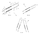
- FIG. 7 depicts the catalytic substrate of FIG. 6 having a current collector disposed therethrough.
- FIG. 8A shows a plurality of tubes in accordance with an exemplary embodiment.
- FIGS. 8B and 8C show a plurality of tubes in accordance with alternate embodiments.
- FIG. 9 shows a cross-section of a tube in accordance with an exemplary embodiment.
- FIG. 10 shows a manifold and a plurality of SOFC tubes in accordance with an exemplary embodiment.
- FIG. 1 is a schematic of a solid oxide fuel cell 10 and surrounding componentry in accordance with a preferred embodiment.
- the fuel cell 10 generates power to run a device 30 or to provide power to a secondary device 28 (such as charging a battery).
- Control electronics 24 and power electronics 26 may be mounted to control the power generation of the SOFC.
- a fuel tank 20 contains a fuel (typically butane, propane, diesel, JET-A, etc.) and a fuel regulator or pump 22 delivers the fuel into a thermal enclosure defined by insulation 12 .
- the SOFC 10 generates significant heat during operation (on the order of 600-1000° C.) and is preferably mounted within the thermal enclosure. The SOFC is most efficient at these higher temperatures, and therefore several design features have been incorporated to heat incoming fuel gas and incoming air.
- an air pump 14 pumps air from a cold air inlet 36 to a recuperator 16 .
- the recuperator is essentially ⁇ heat exchanger which transfers some of the heat from exhaust to the incoming air supplied to the cathode.
- Ambient air for fuel processing is supplied to mix with the fuel in a fuel air mixer 38 in a predetermined ratio, preferably having a sub-stoichiometric quantity of oxygen so that processing of the fuel gas takes place at the catalytic substrate 32 as described in greater detail below.
- Processing is understood here to mean conversion of a fuel to a gas which can be used by the SOFC 10 , typically containing carbon monoxide and hydrogen gas.
- the heated air circulates along the active area and participates in electrochemically transforming the fuel gas into electricity and exhaust gases.
- FIG. 2 shows a schematic of a cross section of the preferred embodiment of the SOFC of FIG. 1 , showing the fuel air mixture being introduced into the thermal enclosure through a series of tubes 40 .
- the actual number of tubes depends in part on the desired power output of the SOFC.
- a plurality of tubes is preferably mounted on a manifold 45 , as seen in FIG. 3 .
- Each tube 40 has an interior 41 and an exterior 43 (shown in FIG. 4 ).
- an anode material is positioned on the interior, and an electrolyte 47 exteriorly surrounds the anode.
- the entire tube 40 may have an interior layer of anode and a layer of electrolyte circumferentially surrounding the anode, so that the anode is remote from the exterior 43 of the tube and the electrolyte is remote from the interior 41 of the tube.
- a cathode 48 is positioned around the exterior 43 of the tube 40 , defining an active area 44 , also preferably remote from the interior of the tube.
- Fuel gas flows from the manifold 45 , then to the catalytic substrate, and then to the active area 44 within each tube.
- the catalytic substrate may be positioned immediately preceding (in terms of fuel gas flow) the active area and within the thermal enclosure so that heat generated at the catalytic substrate helps preheat the fuel gases.
- air from air inlet 36 passes through the recuperator 16 and is heated by an exhaust stream of gases moving separately through the recuperator.
- the air travels through an air inlet tube 58 past the active areas 44 of the fuel cells to an area generally adjacent the catalytic substrates 32 .
- Residual oxygen in the heated inlet air is used to completely combust any residual fuel in the exhaust stream at the burner region 97 .
- a catalytic element may be positioned at the burner region to help with combustion.
- each tube 40 can comprise a 1 mm-20 mm diameter tube with at least three layers, an inner layer of anode, a middle layer of electrolyte, and an outer layer of cathode.
- the anode comprises, for example, a porous cermet of nickel and yttria stabilized zirconia (YSZ).
- the electrolyte can comprise a thin membrane of YSZ.
- the cathode can comprise, for example, a porous lanthanum strontium manganate (LSM).
- LSM porous lanthanum strontium manganate
- the catalytic substrate 32 which partially oxidizes the fuel gas, is positioned inside the tube, advantageously eliminating the need and expense of an external processing device. Moreover, significant heat is generated at the catalytic substrate 32 when a fuel gas is introduced, and this heat is useful in increasing the temperature of the gases to a level where the fuel cell is more efficient in generating electrical power.
- the catalytic substrate 32 can comprise, for example, particles of a suitable metal such as platinum or other noble metals such as palladium, rhodium, iridium, osmium, or their alloys. Other suitable materials for use as a catalytic substrate can comprise oxides, carbides, and nitrides.
- the catalytic substrate may comprise a wire, a porous bulk insert of a catalytically active material, or a thin “ribbon” which would have the effect of increasing the ratio of surface area to volume.
- the catalytic substrate 32 comprises a supported catalyst. Supported catalysts consist of very fine scale catalyst particles supported on a substrate made of, for example a ceramic such as aluminum oxide.
- the catalytic substrate is honeycomb shaped, provided with a series of openings 68 which the fuel gas passes through as it is processed.
- the outer diameter of the honeycomb catalytic substrate is smaller than the inner diameter of the of SOFC tube 40 .
- the honeycombed catalytic substrate may also be provided with spaces through which any current collector wires may pass.
- Other materials suitable for use as a catalytic substrate will be readily apparent to those skilled in the art given the benefit of this disclosure.
- the catalytic substrate 32 is shown in FIGS. 1-2 positioned inside the thermal enclosure defined by the insulation 12 .
- FIG. 3 shows the insulation 12 removed showing tubes 40 of the SOFC bundled together by manifold 45 .
- tubes 40 of the SOFC bundled together by manifold 45 .
- manifold 45 tubes 40 of the SOFC bundled together by manifold 45 .
- a series of tubes can be assembled together into a close fitting compartment surrounded by insulation 12 .
- cold hydrocarbon fuel and oxygen advantageously can be introduced to the SOFC through tubes closed off at the manifold with conventional or “cold seals” such as adhesives and sealants.
- FIG. 6 shows an alternate preferred embodiment of a tube-shaped catalytic substrate 132 where an opening 61 may be provided to receive a current collector.
- a packed bed of catalytic substrate beads may be used, with the beads either arranged in an orderly fashion or randomly packed.
- FIG. 4 shows a single tube 40 .
- Extending along the entire length of the tube 40 along its interior 43 is the anode, and extending circumferentially around the anode is the electrolyte.
- the cathode need only be positioned at the active area 44 , shown in FIG. 4 positioned circumferentially around at least part of the tube.
- the catalytic substrate 32 is positioned within the tube and spaced apart from the active area.
- a spacer element 46 is provided which physically isolates the catalytic substrate 32 from the tube 40 . This is advantageous in that when fuel passes through the catalytic substrate, significant heat is generated. Spacer element helps thermally isolate the tube, thereby reducing heat shock and related stresses.
- the spacer element has a fixed end and a free end, and is mounted to the tube 40 at the fixed end.
- the catalytic substrate is positioned near the free end.
- the spacer element 46 can comprise, for example, a metal such as stainless steel or a ceramic such as zirconia or alumina. Other compositions for the spacer element will be readily apparent to those skilled in the art given the benefit of this disclosure.
- the internal catalytic substrates can be combined with different compositions in series to effect controlled ignition, thermal distribution and reaction, as desired.
- a fuel mixture consisting of one or more of water vapor, fuel, and oxygen can first pass over a catalytic substrate which partially oxidizes a portion of the fuel to create a hot mixture of the remaining fuel, and one or more of partially reformed fuel, hydrogen, carbon dioxide, carbon monoxide, and water.
- the heated fuel-water from the partial oxidation reaction could then undergo endothermic steam reforming in a downstream internal reactor or across the same reactor (tube) to produce a desired reformed fuel.
- This type of fuel processing is known as autothermal reforming.
- a suitable mixture of fuel and water vapor used in combination with one or more catalytic substrates may be used to transform a hydrocarbon into a desired reformed fuel. Additional catalytic materials may be applied to promote a ‘water gas shift’ reaction which would enrich the hydrogen content of a fuel gas stream.
- FIG. 7 shows the substrate 132 with the opening 61 receiving a current collector 70 , therethrough.
- FIG. 8A shows multiple tubes (tubes 40 ) comprising an anode 49 , the electrolyte 47 , and the cathode 48 disposed on a portion of the electrolyte 47 defining an active area 44 .
- a cathode current collector is wrapped around an exterior of the tube 80 a length of the active area 44 .
- FIG. 8B shows multiple tubes (tubes 140 ) in which is a current collector 170 electrically connects the tubes 140 in separate bundles in a parallel connection. In one embodiment, electrical current being supplied to each bundle of cells can be controlled separately by utilizing a diode, switch or other electric circuit component.
- FIG. 8C shows multiple tubes ( 240 ) in which a current collector 170 electrically connects the tubes 240 in a series connection such that an anode of a first fuel cell tube is connected to a cathode of a second fuel cell tube.
- FIG. 9 shows a cross-section of the tube 40 .
- the anode current collector 70 includes an elongated portion 72 and a brush portion 74 .
- the elongated portion 72 is relatively narrow in diameter and extends through the catalytic substrate 132 and an inner length of the spacer element 46 .
- the exemplary brush portion 74 comprises a wire brush having an inner core 101 and a plurality of loop members 102 extending therefrom.
- the inner core 101 functions as an arterial electrical conduit providing current conduction the length of the brush portion 74 .
- the loop members have resilient properties and overall diameter of the anode current collector 74 can be set so that the loop members 102 are compressed against an inner wall of the fuel cell tube 40 proximate the active portion 44 . Continuous lengths of compressed loop members 102 contact the anode 49 of the fuel cell tube 18 to promote electrical contact with the anode 49 .
- the anode current collector 70 remains mechanically complaint allowing the anode current collector 74 to distribute forces created by mechanical and thermal expansion stresses so that the brush portion 74 maintains contact with the anode layer 49 .
- the loop members route electrons relatively short distances between the anode layer 49 and the inner core 101 .
- the loop members 102 have space therebetween to allow fuel to pass between the loop members.
- the loop members provide a calibrated cross section to provide a selected amount of backpressure.
- the anode current collector 74 comprises an electrically conductive metal. Since the anode current collector 74 brush members is positioned in fuel gas and in processed fuel gas, the anode current collector 74 is formed from material that maintains conductivity in the operating environment of the inner chamber of the fuel cell tube 40 . In alternate embodiments, other current collector designs can be utilized including current collectors with a brush member comprising bristle members or other shapes contacting the anode 48 . Exemplary materials for the anode current collector include stainless steel, copper and copper alloys, silver and silver alloys, and nickel and nickel alloys.
- the tubes 40 have the current collectors 70 extending from active areas 40 of tubes 80 through the substrate 132 , through the spacer elements 46 and exiting a fuel inlet (‘FUEL’) of the spacer element 46 .
- Anodes of individual tubes can be electrically connected to each other by the current collector 70 .
- FIG. 10 shows an exploded prospective view of the fuel cell 10 .
- the manifold 45 includes a faceplate 39 comprising an air and fuel inlet 37 , a ring member 41 , and a base portion 43 .
- the faceplate 39 can form a gas-tight seal with the base portion 43 with the ring member disposed therebetween such that fuel can routed between from the fuel inlet 37 to a gas-tight inner chamber defined by the face plate 39 and the base portion 43 .
- the term gas-tight as used herein is used to refer substantially preventing fluid flow circumferentially out of the inner chamber, thus the inner chamber routes substantially all fluid from the air and fuel inlet 37 through the inner chamber to the plurality of spacer 46 .
- the base portion 43 further includes connection members 47 to further provide a seal between the inner chamber and the spacers 46 .
- the fuel cell system 10 further includes a support member 41 having tubes 40 routed therethrough.
- the elongated portion 74 of the current collectors 40 can be disposed though the opening of the catalytic substrate 132 inside the spacer elements, routed through the interior of the spacer elements, and electrically connected to each other at the manifold.
- the anode current collector 70 and the spacer members 46 can be inserted into the tubes 40 and the spacer members 46 can be sealed to fuel cell tube utilizing a sealant, for example a ceramic sealant or a silicon based sealant, (not shown) disposed around an exterior spacer members 46 .
Abstract
Description
Claims (20)
Priority Applications (1)
| Application Number | Priority Date | Filing Date | Title |
|---|---|---|---|
| US12/430,926 US8080346B2 (en) | 2003-10-30 | 2009-04-28 | Current collector for solid oxide fuel cell tube with internal fuel processing |
Applications Claiming Priority (3)
| Application Number | Priority Date | Filing Date | Title |
|---|---|---|---|
| US51577903P | 2003-10-30 | 2003-10-30 | |
| US10/979,017 US7547484B2 (en) | 2003-10-30 | 2004-11-01 | Solid oxide fuel cell tube with internal fuel processing |
| US12/430,926 US8080346B2 (en) | 2003-10-30 | 2009-04-28 | Current collector for solid oxide fuel cell tube with internal fuel processing |
Related Parent Applications (1)
| Application Number | Title | Priority Date | Filing Date |
|---|---|---|---|
| US10/979,017 Continuation-In-Part US7547484B2 (en) | 2003-10-30 | 2004-11-01 | Solid oxide fuel cell tube with internal fuel processing |
Publications (2)
| Publication Number | Publication Date |
|---|---|
| US20100075192A1 US20100075192A1 (en) | 2010-03-25 |
| US8080346B2 true US8080346B2 (en) | 2011-12-20 |
Family
ID=42037993
Family Applications (1)
| Application Number | Title | Priority Date | Filing Date |
|---|---|---|---|
| US12/430,926 Active 2025-10-25 US8080346B2 (en) | 2003-10-30 | 2009-04-28 | Current collector for solid oxide fuel cell tube with internal fuel processing |
Country Status (1)
| Country | Link |
|---|---|
| US (1) | US8080346B2 (en) |
Families Citing this family (4)
| Publication number | Priority date | Publication date | Assignee | Title |
|---|---|---|---|---|
| US20110189587A1 (en) * | 2010-02-01 | 2011-08-04 | Adaptive Materials, Inc. | Interconnect Member for Fuel Cell |
| US20110262819A1 (en) * | 2010-04-23 | 2011-10-27 | Crumm Aaron T | Solid oxide fuel cell module with current collector |
| US20120077099A1 (en) * | 2010-09-23 | 2012-03-29 | Adaptive Materials, Inc. | Solid oxide fuel cell with multiple fuel streams |
| CN106941185B (en) * | 2017-04-11 | 2019-06-25 | 佛山索弗克氢能源有限公司 | SOFC tubular type is oxygen debt, and electrode is reformed in catalysis certainly |
Citations (1)
| Publication number | Priority date | Publication date | Assignee | Title |
|---|---|---|---|---|
| US7695841B2 (en) * | 2003-10-30 | 2010-04-13 | Adaptive Materials, Inc. | Solid oxide fuel cell tube with internal fuel processing |
-
2009
- 2009-04-28 US US12/430,926 patent/US8080346B2/en active Active
Patent Citations (1)
| Publication number | Priority date | Publication date | Assignee | Title |
|---|---|---|---|---|
| US7695841B2 (en) * | 2003-10-30 | 2010-04-13 | Adaptive Materials, Inc. | Solid oxide fuel cell tube with internal fuel processing |
Also Published As
| Publication number | Publication date |
|---|---|
| US20100075192A1 (en) | 2010-03-25 |
Similar Documents
| Publication | Publication Date | Title |
|---|---|---|
| US7695841B2 (en) | Solid oxide fuel cell tube with internal fuel processing | |
| US7767329B2 (en) | Solid oxide fuel cell with improved current collection | |
| US20100086824A1 (en) | Assemblies of hollow electrode electrochemical devices | |
| US6811913B2 (en) | Multipurpose reversible electrochemical system | |
| US4728584A (en) | Fuel cell generator containing self-supporting high gas flow solid oxide electrolyte fuel cells | |
| US5858314A (en) | Thermally enhanced compact reformer | |
| US8343689B2 (en) | Solid oxide fuel cell with improved current collection | |
| CA2051525C (en) | Internal natural gas reformer-dividers for a solid oxide fuel cell generator configuration | |
| US7892684B2 (en) | Heat exchanger for fuel cell stack | |
| US6440596B1 (en) | Solid-oxide fuel cell hot assembly | |
| US20160099476A1 (en) | Sofc-conduction | |
| US20030054215A1 (en) | Compact integrated solid oxide fuel cell system | |
| EP0242200A1 (en) | Fuel cell generators | |
| US7507489B2 (en) | Honeycomb type solid electrolytic fuel cell | |
| AU2002219941A1 (en) | Multipurpose reversible electrochemical system | |
| WO2002069430A2 (en) | Internal reforming improvements for fuel cells | |
| US8080346B2 (en) | Current collector for solid oxide fuel cell tube with internal fuel processing | |
| JP4897273B2 (en) | Fuel cell | |
| US20120077099A1 (en) | Solid oxide fuel cell with multiple fuel streams | |
| JP2005019034A (en) | Solid oxide fuel cell | |
| RU2447545C2 (en) | Systems of solid oxide fuel cells with improved gas chanelling and heat exchange | |
| JP5448985B2 (en) | Auxiliary device for solid oxide fuel cell, solid oxide fuel cell, and solid oxide fuel cell system | |
| JPH08183603A (en) | Reformer for fuel cell power generator and fuel cell power generator |
Legal Events
| Date | Code | Title | Description |
|---|---|---|---|
| AS | Assignment |
Owner name: ADAPTIVE MATERIALS, INC., MICHIGAN Free format text: ASSIGNMENT OF ASSIGNORS INTEREST;ASSIGNORS:CRUMM, AARON;LABRECHE, TIMOTHY;REILLY, CHRISTOPHER;REEL/FRAME:025563/0178 Effective date: 20101222 |
|
| STCF | Information on status: patent grant |
Free format text: PATENTED CASE |
|
| FEPP | Fee payment procedure |
Free format text: PAYOR NUMBER ASSIGNED (ORIGINAL EVENT CODE: ASPN); ENTITY STATUS OF PATENT OWNER: LARGE ENTITY |
|
| FPAY | Fee payment |
Year of fee payment: 4 |
|
| AS | Assignment |
Owner name: UNDERSEA SENSOR SYSTEMS, INC., INDIANA Free format text: MERGER AND CHANGE OF NAME;ASSIGNORS:ADAPTIVE MATERIALS, INC.;UNDERSEA SENSOR SYSTEMS, INC.;REEL/FRAME:034937/0543 Effective date: 20141031 |
|
| AS | Assignment |
Owner name: ADAPTIVE ENERGY, LLC, MICHIGAN Free format text: ASSIGNMENT OF ASSIGNORS INTEREST;ASSIGNOR:UNDERSEA SENSOR SYSTEMS, INC.;REEL/FRAME:047856/0720 Effective date: 20181221 |
|
| FEPP | Fee payment procedure |
Free format text: ENTITY STATUS SET TO SMALL (ORIGINAL EVENT CODE: SMAL); ENTITY STATUS OF PATENT OWNER: SMALL ENTITY |
|
| MAFP | Maintenance fee payment |
Free format text: PAYMENT OF MAINTENANCE FEE, 8TH YR, SMALL ENTITY (ORIGINAL EVENT CODE: M2552); ENTITY STATUS OF PATENT OWNER: SMALL ENTITY Year of fee payment: 8 |
|
| FEPP | Fee payment procedure |
Free format text: ENTITY STATUS SET TO UNDISCOUNTED (ORIGINAL EVENT CODE: BIG.); ENTITY STATUS OF PATENT OWNER: LARGE ENTITY |
|
| AS | Assignment |
Owner name: CAPITAL SOUTHWEST CORPORATION, TEXAS Free format text: SECURITY INTEREST;ASSIGNOR:ADAPTIVE ENERGY, LLC;REEL/FRAME:063407/0516 Effective date: 20230421 |
|
| MAFP | Maintenance fee payment |
Free format text: PAYMENT OF MAINTENANCE FEE, 12TH YEAR, LARGE ENTITY (ORIGINAL EVENT CODE: M1553); ENTITY STATUS OF PATENT OWNER: LARGE ENTITY Year of fee payment: 12 |