US8079253B2 - Combustion chamber pressure sensor - Google Patents
Combustion chamber pressure sensor Download PDFInfo
- Publication number
- US8079253B2 US8079253B2 US12/573,515 US57351509A US8079253B2 US 8079253 B2 US8079253 B2 US 8079253B2 US 57351509 A US57351509 A US 57351509A US 8079253 B2 US8079253 B2 US 8079253B2
- Authority
- US
- United States
- Prior art keywords
- combustion chamber
- chamber pressure
- sensor body
- pressure sensor
- sealing element
- Prior art date
- Legal status (The legal status is an assumption and is not a legal conclusion. Google has not performed a legal analysis and makes no representation as to the accuracy of the status listed.)
- Expired - Fee Related, expires
Links
- 238000002485 combustion reaction Methods 0.000 title claims abstract description 79
- 238000007789 sealing Methods 0.000 claims abstract description 49
- OKTJSMMVPCPJKN-UHFFFAOYSA-N Carbon Chemical compound [C] OKTJSMMVPCPJKN-UHFFFAOYSA-N 0.000 claims description 3
- 229910002804 graphite Inorganic materials 0.000 claims description 3
- 239000010439 graphite Substances 0.000 claims description 3
- -1 polytetrafluoroethylene Polymers 0.000 claims 1
- 229920001343 polytetrafluoroethylene Polymers 0.000 claims 1
- 239000004810 polytetrafluoroethylene Substances 0.000 claims 1
- 230000005540 biological transmission Effects 0.000 description 3
- 238000009434 installation Methods 0.000 description 3
- 239000000463 material Substances 0.000 description 3
- 229910000831 Steel Inorganic materials 0.000 description 2
- 239000004809 Teflon Substances 0.000 description 2
- 229920006362 Teflon® Polymers 0.000 description 2
- 238000013459 approach Methods 0.000 description 2
- 238000001816 cooling Methods 0.000 description 2
- 230000008878 coupling Effects 0.000 description 2
- 238000010168 coupling process Methods 0.000 description 2
- 238000005859 coupling reaction Methods 0.000 description 2
- 230000000694 effects Effects 0.000 description 2
- 239000013013 elastic material Substances 0.000 description 2
- 239000010959 steel Substances 0.000 description 2
- 230000006399 behavior Effects 0.000 description 1
- 229910010293 ceramic material Inorganic materials 0.000 description 1
- 238000010276 construction Methods 0.000 description 1
- 238000006073 displacement reaction Methods 0.000 description 1
- 239000000446 fuel Substances 0.000 description 1
- 230000017525 heat dissipation Effects 0.000 description 1
- 230000013011 mating Effects 0.000 description 1
- 239000002184 metal Substances 0.000 description 1
- 230000005693 optoelectronics Effects 0.000 description 1
- 230000000284 resting effect Effects 0.000 description 1
- 239000004065 semiconductor Substances 0.000 description 1
Images

Classifications
-
- G—PHYSICS
- G01—MEASURING; TESTING
- G01L—MEASURING FORCE, STRESS, TORQUE, WORK, MECHANICAL POWER, MECHANICAL EFFICIENCY, OR FLUID PRESSURE
- G01L23/00—Devices or apparatus for measuring or indicating or recording rapid changes, such as oscillations, in the pressure of steam, gas, or liquid; Indicators for determining work or energy of steam, internal-combustion, or other fluid-pressure engines from the condition of the working fluid
- G01L23/26—Details or accessories
-
- G—PHYSICS
- G01—MEASURING; TESTING
- G01L—MEASURING FORCE, STRESS, TORQUE, WORK, MECHANICAL POWER, MECHANICAL EFFICIENCY, OR FLUID PRESSURE
- G01L23/00—Devices or apparatus for measuring or indicating or recording rapid changes, such as oscillations, in the pressure of steam, gas, or liquid; Indicators for determining work or energy of steam, internal-combustion, or other fluid-pressure engines from the condition of the working fluid
- G01L23/08—Devices or apparatus for measuring or indicating or recording rapid changes, such as oscillations, in the pressure of steam, gas, or liquid; Indicators for determining work or energy of steam, internal-combustion, or other fluid-pressure engines from the condition of the working fluid operated electrically
Definitions
- combustion chamber pressure sensors for detecting the pressure prevailing in the combustion chamber of an internal combustion engine.
- Known combustion chamber pressure sensors usually have a longitudinal sensor body, which can be placed into a receiving opening on the cylinder head of the internal combustion engine.
- Such a combustion chamber pressure sensor is described in German Patent No. DE 103 12 174, for instance, which describes a combustion chamber pressure sensor whose housing forms a bore hole into which a transmission plunger made of ceramic material is inserted, whose one end is sitting on a measuring element and acting on it such that a measuring signal is generated which is proportional to the pressure to be detected, and whose other end is resting on a diaphragm sealing the bore.
- German Patent No. DE 10 2005 025 062 describes a combustion chamber pressure sensor, in which the sensor element detecting the combustion chamber pressure is integrated into the housing of a sheathed-element glow plug.
- the known combustion chamber pressure sensors use a conical sealing seat as a sealing device to seal the sensor body in the receiving bore on the cylinder head of the internal combustion engine.
- the steel jacket of the sensor body is provided with a conical sealing surface at its end on the side of the combustion chamber.
- the outer jacket has a screw thread with whose aid the sensor body is able to be screwed into the receiving bore, thereby pressing the conical sealing seat of the sensor body against a correspondingly shaped counter surface on the cylinder head, so that sealing is achieved.
- the conical sealing surface is placed as far forward as possible on the sensor body on the combustion chamber side, while the screw thread, due to the installation situation at the internal combustion engine, should be placed as far away as possible from the end of the sensor body on the combustion chamber side.
- the sensor body must absorb the torque applied during the screw-fitting and the resulting axial forces acting in the direction of the longitudinal extension virtually across its entire longitudinal extension.
- the sensor body of the known combustion chamber pressure sensors is virtually clamped between the conical sealing seat and the screw thread section, which is why deformations of the cylinder head caused by the combustion chamber pressure and also thermal expansions caused by the combustion process in the combustion chamber are transmitted to the steel jacket of the combustion chamber pressure sensor in their entirety. If the measuring element is not sufficiently decoupled from the sensor body, these deformations and thermal expansions are transmitted to the measuring element and may cause measuring errors in the measuring element.
- the combustion chamber pressure sensor according to the present invention makes it possible to retain the advantages obtained by placing the sealing means very much forward on the side of the sensor body facing the combustion chamber pressure, and an excellent thermal coupling of the sensor body to the cylinder head of the internal combustion engine surrounding the receiving bore is obtained at the same time.
- the sensor body is not clamped between the sealing device and the affixation means in the axial direction, so that no axial twisting advantageously occurs between these sections of the sensor body, and neither the torque applied during the screw-fitting nor an axial force resulting therefrom are transmitted to the measuring element.
- forces and deformations that arise in the cylinder head during the combustion process do not lead to measuring errors in the measuring element.
- a complicated mechanical decoupling of measuring element and sensor body in the interior of the combustion chamber pressure sensor is therefore not necessary.
- the sealing element is advantageously made from a heat-resistant elastic material, so that, for one, the sealing force required for sealing is able to be generated from radial bracing of the sealing element in the cylinder head and, for another, the sealing element easily withstands the temperatures inside the combustion chamber.
- Deposits within the receiving bore of combustion residue on the surface of the sealing element facing the combustion chamber advantageously increase the sealing effect and the thermal coupling of the sensor body to the cylinder head.
- the sealing element takes the shape of a ring and may simply be slipped onto the sensor body, for example.
- the sealing element By giving the outer diameter of the sealing element a larger diameter than the inner diameter of the receiving bore on the cylinder head, the sealing element is advantageously prestressed against the inner wall of the receiving bore when the sensor body is inserted into the receiving bore, thereby achieving effective sealing.
- the sealing element has high thermal conductivity, so that the combustion chamber pressure sensor is thermally coupled to the cylinder head in a very satisfactory manner, and effective cooling of the combustion chamber pressure sensor with the aid of the cooling means provided on the cylinder of the internal combustion chamber is able to take place. It is especially advantageous to form the sealing element from graphite or Teflon, because these materials have the required elasticity and provide high thermal conductivity at the same time.
- the sealing element may be designed in the shape of a bushing, for example, and fixed in place in an annular groove on the outer jacket of the sensor body.
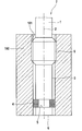
- FIG. 1 shows a schematic cross section through the combustion chamber pressure sensor according to the present invention, in its installation position in the receiving bore of an internal combustion engine according to a first exemplary embodiment of the present invention.
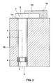
- FIG. 2 shows a schematic cross section through the combustion chamber pressure sensor according to the present invention, in its installation position in the receiving bore of an internal combustion engine according to a second exemplary embodiment of the present invention.
- FIG. 1 shows a first exemplary embodiment of a combustion chamber pressure sensor according to the present invention in a heavily simplified development.
- the combustion chamber pressure sensor includes an essentially cylindrical sensor body 1 , which extends along a longitudinal axis 2 and simultaneously forms the sensor housing of the combustion chamber pressure sensor.
- the internal structure of the combustion chamber pressure sensor is not shown in FIG. 1 and also not relevant for understanding the present invention.
- the combustion chamber pressure sensor may have the internal structure shown in German Patent No. DE 103 12 174, including a transmission plunger and a diaphragm on the side facing the combustion chamber pressure.
- any other types of sensors are possible as well.
- the combustion chamber pressure sensor shown in FIG. 1 absorbs the combustion chamber pressure at its end face 6 facing the combustion chamber.
- a diaphragm, a pressure transmission pin or some other suitable element may be disposed there, whose deformation or displacement under the action of the pressure prevailing in the combustion chamber is transmitted to a sensor element situated in the interior of sensor body 1 .
- the combustion chamber pressure sensor is preferably provided with electric connection elements (not shown) for contacting the sensor element in the interior of sensor body 1 .
- Sensor body 1 has an outer jacket 3 whose diameter is smaller than the inner diameter of a receiving bore 101 on a cylinder head of an internal combustion engine 100 , so that the sensor body is able to be inserted into receiving bore 101 via its end face 6 .
- Screw thread section 9 is provided as far away as possible from end face 6 on the combustion chamber side, but still within the longitudinal extension of receiving bore 101 on sensor body 1 .
- outer jacket 3 of sensor body 1 is provided with an annular groove 5 just in front of end face 6 , into which a heat-resistant elastic sealing element 4 is inserted.
- Sealing element 4 surrounds sensor body 1 in the form of a ring and has a bushing-shaped cylindrical form having an inner recess through which the sensor body projects.
- the outer diameter of sealing element 4 is greater than the inner diameter of receiving bore 101 , so that elastic sealing element 4 is pressed together in the radial direction when sensor body 1 is inserted into receiving bore 101 and thereby applies a radial clamping force required to seal the combustion chamber, which force is supported on the inner sheath of receiving bore 101 .
- the sealing element need not have the shape of a bushing. Furthermore, it is also possible to dispense with annular groove 5 and to fix sealing element 4 in place on sensor body 1 in some other manner, or to mount the sealing element in receiving bore 101 and then to slip sensor body 1 through the sealing element fixed in place inside receiving bore 101 .
- sealing element 4 is made from a heat-resistant elastic material.
- heat-resistance denotes the resistance of the material at increased temperatures.
- suitable materials for this purpose are graphite or Teflon, for example.
- FIG. 2 shows a second exemplary embodiment of the combustion chamber pressure sensor according to the present invention.
- sensor body 1 is formed as a cylindrical base element, whose length corresponds to the length of receiving bore 101 .
- End 7 of sensor body 1 facing away from end face 6 on the combustion chamber side is provided with a headpiece 8 , which overlaps receiving bore 101 , so that headpiece 8 makes contact on the side of internal combustion engine 100 facing away from the combustion chamber once sensor body 1 has been inserted.
- headpiece 8 is pressed against the cylinder head of internal combustion engine 100 with the aid of a clamping shoe 102 .
- clamping shoe 102 overlaps headpiece 8 and is fixed in place on the internal combustion engine with the aid of threaded affixation means 102 , for example.
- the combustion chamber pressure sensor according to the present invention may provide signals that represent the combustion chamber pressure for the control of the internal combustion engine, or it may be used to adapt an engine to different fuel qualities having different combustion behaviors.
Landscapes
- Chemical & Material Sciences (AREA)
- Engineering & Computer Science (AREA)
- Combustion & Propulsion (AREA)
- Physics & Mathematics (AREA)
- General Physics & Mathematics (AREA)
- Measuring Fluid Pressure (AREA)
Abstract
Description
Claims (9)
Applications Claiming Priority (3)
| Application Number | Priority Date | Filing Date | Title |
|---|---|---|---|
| DE102008042645.8 | 2008-10-07 | ||
| DE102008042645A DE102008042645A1 (en) | 2008-10-07 | 2008-10-07 | Combustion chamber pressure sensor |
| DE102008042645 | 2008-10-07 |
Publications (2)
| Publication Number | Publication Date |
|---|---|
| US20100083741A1 US20100083741A1 (en) | 2010-04-08 |
| US8079253B2 true US8079253B2 (en) | 2011-12-20 |
Family
ID=41794791
Family Applications (1)
| Application Number | Title | Priority Date | Filing Date |
|---|---|---|---|
| US12/573,515 Expired - Fee Related US8079253B2 (en) | 2008-10-07 | 2009-10-05 | Combustion chamber pressure sensor |
Country Status (3)
| Country | Link |
|---|---|
| US (1) | US8079253B2 (en) |
| JP (1) | JP5679646B2 (en) |
| DE (1) | DE102008042645A1 (en) |
Cited By (1)
| Publication number | Priority date | Publication date | Assignee | Title |
|---|---|---|---|---|
| US20110146393A1 (en) * | 2008-04-23 | 2011-06-23 | Bernd Last | Device and Method for Determining Combustion Chamber Pressure |
Families Citing this family (6)
| Publication number | Priority date | Publication date | Assignee | Title |
|---|---|---|---|---|
| DE102012201751A1 (en) | 2012-02-07 | 2013-08-08 | Robert Bosch Gmbh | sealing arrangement |
| US8839806B2 (en) * | 2012-03-15 | 2014-09-23 | General Electric Company | Pressure tap assembly for turbine system and method for assembly of a pressure tap assembly |
| CN105090502B (en) * | 2014-05-13 | 2017-04-12 | 太仓海嘉车辆配件有限公司 | Sealing device for leak hunting of valve body of dry dual clutch |
| WO2016121723A1 (en) * | 2015-01-29 | 2016-08-04 | シチズンファインデバイス株式会社 | Combustion pressure sensor |
| JP6404776B2 (en) * | 2015-06-09 | 2018-10-17 | 株式会社Soken | Combustion pressure sensor |
| JP6399018B2 (en) * | 2016-03-03 | 2018-10-03 | トヨタ自動車株式会社 | Internal combustion engine |
Citations (9)
| Publication number | Priority date | Publication date | Assignee | Title |
|---|---|---|---|---|
| US5726351A (en) * | 1994-12-19 | 1998-03-10 | AVL Gesellschaft fur Verbrennungskraftmaschinen und Messtechnik m.b.H. Prof.Dr.Dr.h.c. Hans List | Spark plug comprising a force measuring element |
| DE10312174A1 (en) | 2003-03-19 | 2004-10-07 | Robert Bosch Gmbh | Pressure signaler for measuring combustion chamber pressure in a combustion engine has a pressure transfer piston made of ceramic material arranged between a membrane and a pressure measurement element |
| US20050061063A1 (en) * | 2003-09-19 | 2005-03-24 | Beru Ag | Pressure glow plug for a diesel engine |
| DE102005025062A1 (en) | 2005-06-01 | 2006-12-07 | Wilhelm Karmann Gmbh | Testing of components or semi-finished products with a foamed metallic layer |
| US20070209624A1 (en) * | 2004-03-16 | 2007-09-13 | Thomas Ludwig | Sheathed-Element Glow Plug Having An Elastically Mounted Glow Element |
| US20070289370A1 (en) * | 2006-06-20 | 2007-12-20 | Denso Corporation | Combustion pressure sensor |
| US20080229815A1 (en) * | 2007-03-13 | 2008-09-25 | Viacheslav Bekker | Sensor system for measuring pressure |
| US20080302323A1 (en) * | 2004-12-29 | 2008-12-11 | Christoph Kern | Pencil-Type Glow Plug Having an Integrated Combustion Chamber Pressure Sensor |
| US7555932B2 (en) * | 2006-04-20 | 2009-07-07 | Denso Corporation | Combustion pressure sensor |
Family Cites Families (6)
| Publication number | Priority date | Publication date | Assignee | Title |
|---|---|---|---|---|
| CH674550A5 (en) * | 1988-04-08 | 1990-06-15 | Burckhardt Ag Maschf | |
| JP2002081548A (en) * | 2000-09-04 | 2002-03-22 | Honda Motor Co Ltd | Seal structure |
| EP1426563A1 (en) * | 2002-12-03 | 2004-06-09 | BorgWarner Inc. | Turbocharger with ceramic or metallic seal between the turbine and the bearing casing |
| FR2869390B1 (en) * | 2004-04-27 | 2006-07-14 | Siemens Vdo Automotive Sas | BODY OF A PREHEATING CANDLE COMPRISING A PRESSURE SENSOR |
| JP2008101989A (en) * | 2006-10-18 | 2008-05-01 | Toyota Motor Corp | Sensor, its mounting structure and mounting method |
| JP2008191059A (en) * | 2007-02-07 | 2008-08-21 | Citizen Fine Tech Co Ltd | Combustion pressure sensor and attachment structure for the same |
-
2008
- 2008-10-07 DE DE102008042645A patent/DE102008042645A1/en not_active Withdrawn
-
2009
- 2009-10-05 JP JP2009231697A patent/JP5679646B2/en not_active Expired - Fee Related
- 2009-10-05 US US12/573,515 patent/US8079253B2/en not_active Expired - Fee Related
Patent Citations (12)
| Publication number | Priority date | Publication date | Assignee | Title |
|---|---|---|---|---|
| US5726351A (en) * | 1994-12-19 | 1998-03-10 | AVL Gesellschaft fur Verbrennungskraftmaschinen und Messtechnik m.b.H. Prof.Dr.Dr.h.c. Hans List | Spark plug comprising a force measuring element |
| DE10312174A1 (en) | 2003-03-19 | 2004-10-07 | Robert Bosch Gmbh | Pressure signaler for measuring combustion chamber pressure in a combustion engine has a pressure transfer piston made of ceramic material arranged between a membrane and a pressure measurement element |
| US20050061063A1 (en) * | 2003-09-19 | 2005-03-24 | Beru Ag | Pressure glow plug for a diesel engine |
| US7337657B2 (en) * | 2003-09-19 | 2008-03-04 | Beru Ag | Pressure glow plug for a diesel engine |
| US20070209624A1 (en) * | 2004-03-16 | 2007-09-13 | Thomas Ludwig | Sheathed-Element Glow Plug Having An Elastically Mounted Glow Element |
| US20080302323A1 (en) * | 2004-12-29 | 2008-12-11 | Christoph Kern | Pencil-Type Glow Plug Having an Integrated Combustion Chamber Pressure Sensor |
| US7581520B2 (en) * | 2004-12-29 | 2009-09-01 | Robert Bosch Gmbh | Pencil-type glow plug having an integrated combustion chamber pressure sensor |
| DE102005025062A1 (en) | 2005-06-01 | 2006-12-07 | Wilhelm Karmann Gmbh | Testing of components or semi-finished products with a foamed metallic layer |
| US7555932B2 (en) * | 2006-04-20 | 2009-07-07 | Denso Corporation | Combustion pressure sensor |
| US20070289370A1 (en) * | 2006-06-20 | 2007-12-20 | Denso Corporation | Combustion pressure sensor |
| US7624620B2 (en) * | 2006-06-20 | 2009-12-01 | Denso Corporation | Combustion pressure sensor |
| US20080229815A1 (en) * | 2007-03-13 | 2008-09-25 | Viacheslav Bekker | Sensor system for measuring pressure |
Cited By (2)
| Publication number | Priority date | Publication date | Assignee | Title |
|---|---|---|---|---|
| US20110146393A1 (en) * | 2008-04-23 | 2011-06-23 | Bernd Last | Device and Method for Determining Combustion Chamber Pressure |
| US8397556B2 (en) * | 2008-04-23 | 2013-03-19 | Borgwarner Beru Systems Gmbh | Device and method for determining combustion chamber pressure |
Also Published As
| Publication number | Publication date |
|---|---|
| US20100083741A1 (en) | 2010-04-08 |
| DE102008042645A1 (en) | 2010-04-08 |
| JP2010091563A (en) | 2010-04-22 |
| JP5679646B2 (en) | 2015-03-04 |
Similar Documents
| Publication | Publication Date | Title |
|---|---|---|
| US8079253B2 (en) | Combustion chamber pressure sensor | |
| EP1096141B1 (en) | Glow Plug having a combustion pressure sensor | |
| US7730771B2 (en) | Device for detecting the combustion-chamber pressure in an internal combustion engine | |
| US8397556B2 (en) | Device and method for determining combustion chamber pressure | |
| US7431003B2 (en) | Sheathed-element glow plug having an elastically mounted glow element | |
| US7839056B2 (en) | Piezoelectric pressure sensor | |
| JPH03293534A (en) | Mounting apparatus for pressure sensor | |
| US9683742B2 (en) | Pressure sensor integrated glow plug | |
| US9541291B2 (en) | Pressure measuring glow plug | |
| US9874195B2 (en) | Pressure-measuring glow plug device | |
| JP3900059B2 (en) | Mounting structure and mounting method of glow plug with combustion sensor and glow plug with combustion pressure sensor | |
| KR101614625B1 (en) | Glow plug equipped with pressure sensor | |
| US20080223139A1 (en) | Combustion pressure sensor | |
| CN102150025B (en) | Device incorporating a pressure sensor for measuring pressure in an internal combustion engine and body of such a device | |
| CN103988022B (en) | Glow plug for pressure measurement | |
| CN102150027B (en) | Device incorporating a pressure sensor for measuring pressures within an internal combustion engine | |
| CN102150026B (en) | Device including a pressure sensor for measuring pressures inside the combustion chamber of an engine | |
| US20110056925A1 (en) | Pressure Measuring Glow Plug | |
| US20080264373A1 (en) | Sheathed Element Glow Plug Having a Combustion Chamber Pressure Sensor | |
| JP4753389B2 (en) | Sheath type glow plug with combustion chamber pressure sensor and seal element | |
| JP4922822B2 (en) | Combustion pressure sensor | |
| JP2007526420A (en) | Apparatus for detecting combustion chamber pressure in an internal combustion engine | |
| JP2008537046A (en) | Sheath type glow plug with built-in pressure measuring element | |
| US20120198924A1 (en) | Cylinder Pressure Sensor | |
| JP4207070B2 (en) | Glow plug with combustion sensor |
Legal Events
| Date | Code | Title | Description |
|---|---|---|---|
| AS | Assignment |
Owner name: ROBERT BOSCH GMBH,GERMANY Free format text: ASSIGNMENT OF ASSIGNORS INTEREST;ASSIGNORS:SCHOLZEN, HOLGER;LEDERMANN, MARKUS;SIGNING DATES FROM 20091119 TO 20091125;REEL/FRAME:023621/0988 Owner name: ROBERT BOSCH GMBH, GERMANY Free format text: ASSIGNMENT OF ASSIGNORS INTEREST;ASSIGNORS:SCHOLZEN, HOLGER;LEDERMANN, MARKUS;SIGNING DATES FROM 20091119 TO 20091125;REEL/FRAME:023621/0988 |
|
| ZAAA | Notice of allowance and fees due |
Free format text: ORIGINAL CODE: NOA |
|
| ZAAB | Notice of allowance mailed |
Free format text: ORIGINAL CODE: MN/=. |
|
| STCF | Information on status: patent grant |
Free format text: PATENTED CASE |
|
| FPAY | Fee payment |
Year of fee payment: 4 |
|
| MAFP | Maintenance fee payment |
Free format text: PAYMENT OF MAINTENANCE FEE, 8TH YEAR, LARGE ENTITY (ORIGINAL EVENT CODE: M1552); ENTITY STATUS OF PATENT OWNER: LARGE ENTITY Year of fee payment: 8 |
|
| FEPP | Fee payment procedure |
Free format text: MAINTENANCE FEE REMINDER MAILED (ORIGINAL EVENT CODE: REM.); ENTITY STATUS OF PATENT OWNER: LARGE ENTITY |
|
| LAPS | Lapse for failure to pay maintenance fees |
Free format text: PATENT EXPIRED FOR FAILURE TO PAY MAINTENANCE FEES (ORIGINAL EVENT CODE: EXP.); ENTITY STATUS OF PATENT OWNER: LARGE ENTITY |
|
| STCH | Information on status: patent discontinuation |
Free format text: PATENT EXPIRED DUE TO NONPAYMENT OF MAINTENANCE FEES UNDER 37 CFR 1.362 |
|
| FP | Lapsed due to failure to pay maintenance fee |
Effective date: 20231220 |