US8079209B2 - Urea-SCR system and control method thereof - Google Patents
Urea-SCR system and control method thereof Download PDFInfo
- Publication number
- US8079209B2 US8079209B2 US12/392,818 US39281809A US8079209B2 US 8079209 B2 US8079209 B2 US 8079209B2 US 39281809 A US39281809 A US 39281809A US 8079209 B2 US8079209 B2 US 8079209B2
- Authority
- US
- United States
- Prior art keywords
- urea
- injection amount
- value
- real
- recharging
- Prior art date
- Legal status (The legal status is an assumption and is not a legal conclusion. Google has not performed a legal analysis and makes no representation as to the accuracy of the status listed.)
- Expired - Fee Related, expires
Links
Images


Classifications
-
- F—MECHANICAL ENGINEERING; LIGHTING; HEATING; WEAPONS; BLASTING
- F01—MACHINES OR ENGINES IN GENERAL; ENGINE PLANTS IN GENERAL; STEAM ENGINES
- F01N—GAS-FLOW SILENCERS OR EXHAUST APPARATUS FOR MACHINES OR ENGINES IN GENERAL; GAS-FLOW SILENCERS OR EXHAUST APPARATUS FOR INTERNAL-COMBUSTION ENGINES
- F01N3/00—Exhaust or silencing apparatus having means for purifying, rendering innocuous, or otherwise treating exhaust
- F01N3/08—Exhaust or silencing apparatus having means for purifying, rendering innocuous, or otherwise treating exhaust for rendering innocuous
- F01N3/10—Exhaust or silencing apparatus having means for purifying, rendering innocuous, or otherwise treating exhaust for rendering innocuous by thermal or catalytic conversion of noxious components of exhaust
- F01N3/18—Exhaust or silencing apparatus having means for purifying, rendering innocuous, or otherwise treating exhaust for rendering innocuous by thermal or catalytic conversion of noxious components of exhaust characterised by methods of operation; Control
- F01N3/20—Exhaust or silencing apparatus having means for purifying, rendering innocuous, or otherwise treating exhaust for rendering innocuous by thermal or catalytic conversion of noxious components of exhaust characterised by methods of operation; Control specially adapted for catalytic conversion
- F01N3/206—Adding periodically or continuously substances to exhaust gases for promoting purification, e.g. catalytic material in liquid form, NOx reducing agents
- F01N3/208—Control of selective catalytic reduction [SCR], e.g. by adjusting the dosing of reducing agent
-
- F—MECHANICAL ENGINEERING; LIGHTING; HEATING; WEAPONS; BLASTING
- F01—MACHINES OR ENGINES IN GENERAL; ENGINE PLANTS IN GENERAL; STEAM ENGINES
- F01N—GAS-FLOW SILENCERS OR EXHAUST APPARATUS FOR MACHINES OR ENGINES IN GENERAL; GAS-FLOW SILENCERS OR EXHAUST APPARATUS FOR INTERNAL-COMBUSTION ENGINES
- F01N9/00—Electrical control of exhaust gas treating apparatus
-
- F—MECHANICAL ENGINEERING; LIGHTING; HEATING; WEAPONS; BLASTING
- F01—MACHINES OR ENGINES IN GENERAL; ENGINE PLANTS IN GENERAL; STEAM ENGINES
- F01N—GAS-FLOW SILENCERS OR EXHAUST APPARATUS FOR MACHINES OR ENGINES IN GENERAL; GAS-FLOW SILENCERS OR EXHAUST APPARATUS FOR INTERNAL-COMBUSTION ENGINES
- F01N11/00—Monitoring or diagnostic devices for exhaust-gas treatment apparatus
-
- B—PERFORMING OPERATIONS; TRANSPORTING
- B01—PHYSICAL OR CHEMICAL PROCESSES OR APPARATUS IN GENERAL
- B01D—SEPARATION
- B01D2251/00—Reactants
- B01D2251/20—Reductants
- B01D2251/206—Ammonium compounds
- B01D2251/2062—Ammonia
-
- F—MECHANICAL ENGINEERING; LIGHTING; HEATING; WEAPONS; BLASTING
- F01—MACHINES OR ENGINES IN GENERAL; ENGINE PLANTS IN GENERAL; STEAM ENGINES
- F01N—GAS-FLOW SILENCERS OR EXHAUST APPARATUS FOR MACHINES OR ENGINES IN GENERAL; GAS-FLOW SILENCERS OR EXHAUST APPARATUS FOR INTERNAL-COMBUSTION ENGINES
- F01N2550/00—Monitoring or diagnosing the deterioration of exhaust systems
- F01N2550/05—Systems for adding substances into exhaust
-
- F—MECHANICAL ENGINEERING; LIGHTING; HEATING; WEAPONS; BLASTING
- F01—MACHINES OR ENGINES IN GENERAL; ENGINE PLANTS IN GENERAL; STEAM ENGINES
- F01N—GAS-FLOW SILENCERS OR EXHAUST APPARATUS FOR MACHINES OR ENGINES IN GENERAL; GAS-FLOW SILENCERS OR EXHAUST APPARATUS FOR INTERNAL-COMBUSTION ENGINES
- F01N2560/00—Exhaust systems with means for detecting or measuring exhaust gas components or characteristics
- F01N2560/02—Exhaust systems with means for detecting or measuring exhaust gas components or characteristics the means being an exhaust gas sensor
- F01N2560/026—Exhaust systems with means for detecting or measuring exhaust gas components or characteristics the means being an exhaust gas sensor for measuring or detecting NOx
-
- F—MECHANICAL ENGINEERING; LIGHTING; HEATING; WEAPONS; BLASTING
- F01—MACHINES OR ENGINES IN GENERAL; ENGINE PLANTS IN GENERAL; STEAM ENGINES
- F01N—GAS-FLOW SILENCERS OR EXHAUST APPARATUS FOR MACHINES OR ENGINES IN GENERAL; GAS-FLOW SILENCERS OR EXHAUST APPARATUS FOR INTERNAL-COMBUSTION ENGINES
- F01N2570/00—Exhaust treating apparatus eliminating, absorbing or adsorbing specific elements or compounds
- F01N2570/14—Nitrogen oxides
-
- F—MECHANICAL ENGINEERING; LIGHTING; HEATING; WEAPONS; BLASTING
- F01—MACHINES OR ENGINES IN GENERAL; ENGINE PLANTS IN GENERAL; STEAM ENGINES
- F01N—GAS-FLOW SILENCERS OR EXHAUST APPARATUS FOR MACHINES OR ENGINES IN GENERAL; GAS-FLOW SILENCERS OR EXHAUST APPARATUS FOR INTERNAL-COMBUSTION ENGINES
- F01N2610/00—Adding substances to exhaust gases
- F01N2610/02—Adding substances to exhaust gases the substance being ammonia or urea
-
- F—MECHANICAL ENGINEERING; LIGHTING; HEATING; WEAPONS; BLASTING
- F01—MACHINES OR ENGINES IN GENERAL; ENGINE PLANTS IN GENERAL; STEAM ENGINES
- F01N—GAS-FLOW SILENCERS OR EXHAUST APPARATUS FOR MACHINES OR ENGINES IN GENERAL; GAS-FLOW SILENCERS OR EXHAUST APPARATUS FOR INTERNAL-COMBUSTION ENGINES
- F01N2900/00—Details of electrical control or of the monitoring of the exhaust gas treating apparatus
- F01N2900/04—Methods of control or diagnosing
- F01N2900/0421—Methods of control or diagnosing using an increment counter when a predetermined event occurs
-
- F—MECHANICAL ENGINEERING; LIGHTING; HEATING; WEAPONS; BLASTING
- F01—MACHINES OR ENGINES IN GENERAL; ENGINE PLANTS IN GENERAL; STEAM ENGINES
- F01N—GAS-FLOW SILENCERS OR EXHAUST APPARATUS FOR MACHINES OR ENGINES IN GENERAL; GAS-FLOW SILENCERS OR EXHAUST APPARATUS FOR INTERNAL-COMBUSTION ENGINES
- F01N2900/00—Details of electrical control or of the monitoring of the exhaust gas treating apparatus
- F01N2900/04—Methods of control or diagnosing
- F01N2900/0422—Methods of control or diagnosing measuring the elapsed time
-
- F—MECHANICAL ENGINEERING; LIGHTING; HEATING; WEAPONS; BLASTING
- F01—MACHINES OR ENGINES IN GENERAL; ENGINE PLANTS IN GENERAL; STEAM ENGINES
- F01N—GAS-FLOW SILENCERS OR EXHAUST APPARATUS FOR MACHINES OR ENGINES IN GENERAL; GAS-FLOW SILENCERS OR EXHAUST APPARATUS FOR INTERNAL-COMBUSTION ENGINES
- F01N2900/00—Details of electrical control or of the monitoring of the exhaust gas treating apparatus
- F01N2900/06—Parameters used for exhaust control or diagnosing
- F01N2900/10—Parameters used for exhaust control or diagnosing said parameters being related to the vehicle or its components
- F01N2900/102—Travelling distance
-
- F—MECHANICAL ENGINEERING; LIGHTING; HEATING; WEAPONS; BLASTING
- F01—MACHINES OR ENGINES IN GENERAL; ENGINE PLANTS IN GENERAL; STEAM ENGINES
- F01N—GAS-FLOW SILENCERS OR EXHAUST APPARATUS FOR MACHINES OR ENGINES IN GENERAL; GAS-FLOW SILENCERS OR EXHAUST APPARATUS FOR INTERNAL-COMBUSTION ENGINES
- F01N2900/00—Details of electrical control or of the monitoring of the exhaust gas treating apparatus
- F01N2900/06—Parameters used for exhaust control or diagnosing
- F01N2900/14—Parameters used for exhaust control or diagnosing said parameters being related to the exhaust gas
- F01N2900/1402—Exhaust gas composition
-
- F—MECHANICAL ENGINEERING; LIGHTING; HEATING; WEAPONS; BLASTING
- F01—MACHINES OR ENGINES IN GENERAL; ENGINE PLANTS IN GENERAL; STEAM ENGINES
- F01N—GAS-FLOW SILENCERS OR EXHAUST APPARATUS FOR MACHINES OR ENGINES IN GENERAL; GAS-FLOW SILENCERS OR EXHAUST APPARATUS FOR INTERNAL-COMBUSTION ENGINES
- F01N2900/00—Details of electrical control or of the monitoring of the exhaust gas treating apparatus
- F01N2900/06—Parameters used for exhaust control or diagnosing
- F01N2900/18—Parameters used for exhaust control or diagnosing said parameters being related to the system for adding a substance into the exhaust
- F01N2900/1806—Properties of reducing agent or dosing system
- F01N2900/1808—Pressure
-
- F—MECHANICAL ENGINEERING; LIGHTING; HEATING; WEAPONS; BLASTING
- F01—MACHINES OR ENGINES IN GENERAL; ENGINE PLANTS IN GENERAL; STEAM ENGINES
- F01N—GAS-FLOW SILENCERS OR EXHAUST APPARATUS FOR MACHINES OR ENGINES IN GENERAL; GAS-FLOW SILENCERS OR EXHAUST APPARATUS FOR INTERNAL-COMBUSTION ENGINES
- F01N3/00—Exhaust or silencing apparatus having means for purifying, rendering innocuous, or otherwise treating exhaust
- F01N3/02—Exhaust or silencing apparatus having means for purifying, rendering innocuous, or otherwise treating exhaust for cooling, or for removing solid constituents of, exhaust
- F01N3/021—Exhaust or silencing apparatus having means for purifying, rendering innocuous, or otherwise treating exhaust for cooling, or for removing solid constituents of, exhaust by means of filters
- F01N3/023—Exhaust or silencing apparatus having means for purifying, rendering innocuous, or otherwise treating exhaust for cooling, or for removing solid constituents of, exhaust by means of filters using means for regenerating the filters, e.g. by burning trapped particles
- F01N3/0231—Exhaust or silencing apparatus having means for purifying, rendering innocuous, or otherwise treating exhaust for cooling, or for removing solid constituents of, exhaust by means of filters using means for regenerating the filters, e.g. by burning trapped particles using special exhaust apparatus upstream of the filter for producing nitrogen dioxide, e.g. for continuous filter regeneration systems [CRT]
-
- F—MECHANICAL ENGINEERING; LIGHTING; HEATING; WEAPONS; BLASTING
- F02—COMBUSTION ENGINES; HOT-GAS OR COMBUSTION-PRODUCT ENGINE PLANTS
- F02N—STARTING OF COMBUSTION ENGINES; STARTING AIDS FOR SUCH ENGINES, NOT OTHERWISE PROVIDED FOR
- F02N11/00—Starting of engines by means of electric motors
- F02N11/10—Safety devices
- F02N11/101—Safety devices for preventing engine starter actuation or engagement
-
- Y—GENERAL TAGGING OF NEW TECHNOLOGICAL DEVELOPMENTS; GENERAL TAGGING OF CROSS-SECTIONAL TECHNOLOGIES SPANNING OVER SEVERAL SECTIONS OF THE IPC; TECHNICAL SUBJECTS COVERED BY FORMER USPC CROSS-REFERENCE ART COLLECTIONS [XRACs] AND DIGESTS
- Y02—TECHNOLOGIES OR APPLICATIONS FOR MITIGATION OR ADAPTATION AGAINST CLIMATE CHANGE
- Y02A—TECHNOLOGIES FOR ADAPTATION TO CLIMATE CHANGE
- Y02A50/00—TECHNOLOGIES FOR ADAPTATION TO CLIMATE CHANGE in human health protection, e.g. against extreme weather
- Y02A50/20—Air quality improvement or preservation, e.g. vehicle emission control or emission reduction by using catalytic converters
-
- Y—GENERAL TAGGING OF NEW TECHNOLOGICAL DEVELOPMENTS; GENERAL TAGGING OF CROSS-SECTIONAL TECHNOLOGIES SPANNING OVER SEVERAL SECTIONS OF THE IPC; TECHNICAL SUBJECTS COVERED BY FORMER USPC CROSS-REFERENCE ART COLLECTIONS [XRACs] AND DIGESTS
- Y02—TECHNOLOGIES OR APPLICATIONS FOR MITIGATION OR ADAPTATION AGAINST CLIMATE CHANGE
- Y02T—CLIMATE CHANGE MITIGATION TECHNOLOGIES RELATED TO TRANSPORTATION
- Y02T10/00—Road transport of goods or passengers
- Y02T10/10—Internal combustion engine [ICE] based vehicles
- Y02T10/12—Improving ICE efficiencies
-
- Y—GENERAL TAGGING OF NEW TECHNOLOGICAL DEVELOPMENTS; GENERAL TAGGING OF CROSS-SECTIONAL TECHNOLOGIES SPANNING OVER SEVERAL SECTIONS OF THE IPC; TECHNICAL SUBJECTS COVERED BY FORMER USPC CROSS-REFERENCE ART COLLECTIONS [XRACs] AND DIGESTS
- Y02—TECHNOLOGIES OR APPLICATIONS FOR MITIGATION OR ADAPTATION AGAINST CLIMATE CHANGE
- Y02T—CLIMATE CHANGE MITIGATION TECHNOLOGIES RELATED TO TRANSPORTATION
- Y02T10/00—Road transport of goods or passengers
- Y02T10/10—Internal combustion engine [ICE] based vehicles
- Y02T10/40—Engine management systems
Definitions
- the present invention relates to a urea-SCR system and a control method thereof.
- LNT lean NO x trap
- a post-injection technique is to be used, that is, the fuel is further injected into an exhaust pipe such that the fuel consumption is increased.
- urea-SCR urea-selective catalyst reduction system
- injects a urea solution into the exhaust pipe so as to eliminate the nitrogen oxide in the exhaust gas, and the injected urea is vaporized by thermal energy (at about 156° C.) of the exhaust gas or is decomposed by the catalyst to be transformed to ammonia
- Reaction Formula 1 thereof is as follows. Reaction Formula 1 (NH 2 ) 2 CO+H 2 O ⁇ 2NH 3 +CO 2 Eq. (1)
- Reaction Formula 2 4NH 3 +4NO+O 2 ⁇ 4N 2 +6H 2 O Eq. (2) 4NH 3 +2NO 2 +O 2 ⁇ 3N 2 +6H 2 O Eq. (3) 8NH 3 +6NO 2 ⁇ 7N 2 +12H 2 O Eq. (4) 2NH 3 +NO+NO 2 ⁇ 2N 2 +3H 2 O Eq. (5)
- the present invention has been made in an effort to provide a urea-SCR system and a control method thereof having advantages of effectively diagnosing the urea consumption amount and recharging the urea solution.
- a method for controlling an urea-SCR system may include a first step of calculating a target urea injection amount, a second step that uses urea injection pressure and urea injection time to calculate a real urea injection amount, a third step that calculates a difference value between the target urea injection amount and the real urea injection amount, and monitors the difference value at a predetermined time interval, a fourth step that accumulates difference values for a determined time when the difference value exceeds a predetermined level, and transfers an alarm signal to a driver when the average value thereof exceeds a predetermined level, and/or a fifth step that starts to accumulate a number of engine starts and driving distance after transferring the alarm signal, and when the number of engine starts is larger than a predetermined value or the driving distance is longer than a predetermined value, if the difference value does not become lower than a predetermined level, executes urea recharging means for a driver to charge a urea tank with a urea solution.
- Engine speed and fuel supply amount are measured and an initial NO:NO 2 ratio value among initial NO x is detected, a NO 2 increment that is estimated through temperature of a diesel oxidation catalyst (DOC) and a NO 2 decrement that is analyzed through a pressure difference change amount through a catalytic particulate filter (CPF) temperature and continuous regeneration trap (CRT) effectiveness are reflected or related to the initial NO:NO 2 ratio value to calculate a final NO:NO 2 ratio value, and thereby a reaction molecular ratio with the NH 3 and NO x purification efficiency of the SCR catalyst is determined to calculate the target urea injection amount in the first step.
- DOC diesel oxidation catalyst
- CPF catalytic particulate filter
- CRT continuous regeneration trap
- the real urea injection amount value may be displayed on a cluster in real time for the driver to check the real urea injection amount in the second step.
- the fourth step may further include a step that, if the difference value between the target urea injection amount and the real urea injection amount is less than the predetermined value, updates the average difference value at a predetermined cycle based on the accumulation value of the driving distance.
- the urea recharging means may include an output reduction logic that reduces the output of the engine and a restarting restriction logic that causes the engine to not be restarted in the fifth step. If the difference value is larger than the predetermined value, the output restriction logic or the restarting restriction logic may be operated, if the number of engine starts after transferring the alarm signal is larger than a predetermined value or the accumulation value of the driving distance is longer than a predetermined value after generating the alarm signal.
- a selective catalyst reduction device control system may include a selective catalyst reduction device that is mounted on an exhaust pipe so as to eliminate nitrogen oxide that is included in exhaust gas, a urea tank in which a urea solution is stored, an injector that injects the urea solution that is supplied from the urea tank, and a control portion that calculates a target injection amount and a real injection amount that is to be injected from the injector, and if the difference value between the target injection amount and the real injection amount is larger than a predetermined value, generates an alarm signal.
- the control portion includes a counting portion that counts a number of engine starts after generating the alarm signal, an accumulating portion that accumulates the driving distance after generating the alarm signal, and a recharging induction portion that generates a recharging signal for recharging the urea tank with a urea solution if the difference value is larger than the predetermined value, if the number of engine starts or the accumulated driving distance is larger than the predetermined value.
- the recharging induction portion may prevent the engine from being started.
- the recharging induction portion may restrict the engine output so that the amount of exhaust gas is decreased.
- the control portion may update the average of the difference value at a predetermined cycle, when the difference value between the target injection amount and the real injection amount is less than the predetermined value.
- An alarm lamp or an alarm sound (voice) may be turned on by the alarm signal.
- a recharging lamp or a recharging sound (voice) may be turned on by the recharging signal.
- the urea consumption amount may be continuously monitored, a remaining urea amount may be accurately detected, and the urea recharging may be induced in time such that nitrogen oxide exhausting may be prevented.
- FIG. 1 is a flowchart showing an exemplary method for controlling a urea-SCR system according to the present invention.
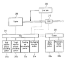
- FIG. 2 is a schematic diagram of an exemplary selective catalyst reduction device according to the present invention.
- FIG. 1 is a flowchart showing a method for controlling a urea-SCR system according to various embodiments of the present invention.
- a target urea injection amount is calculated (S 101 ).
- the target urea injection amount may be calculated as follows. First, engine speed and fuel supply amount are measured and an initial NO:NO 2 ratio value of initial NO x is detected, and a NO 2 increment that is estimated through the temperature of the DOC and the NO 2 decrement that is analyzed through a pressure difference change amount through the catalytic particulate filter (CPF) temperature and continuous regeneration trap (CRT) effectiveness are reflected or related to the initial NO:NO 2 ratio value to calculate a final NO:NO 2 ratio value, and thereby a reaction molecular ratio with the NH 3 and NO x purification efficiency of the SCR catalyst are determined to calculate the target urea injection amount.
- CPF catalytic particulate filter
- CRT continuous regeneration trap
- the NO 2 increment amount may be calculated as follows. First, the oxidation amount of HC inside a diesel oxidation catalyst (DOC) is measured by an exhaust gas temperature sensor, and then the increment amount of the DOC temperature is measured according to the oxidation amount of the HC that is measured above to calculate the NO 2 increment amount.
- DOC diesel oxidation catalyst
- the NO 2 decrement amount may be calculated as follows. First, it is determined whether an amount of soot that is loaded inside the CPF is larger than a predetermined amount by a signal of a pressure difference sensor and it is determined whether the exhaust gas temperature reaches a CRT condition by an exhaust gas temperature sensor in a CPF, and then the pressure difference value during a CRT is measured by the pressure difference sensor to calculate the NO 2 decrement amount.
- the urea injection pressure and the urea injection time may be measured to calculate the real urea injection amount (S 103 ), and the value is transferred to a cluster (S 105 ).
- the urea injection pressure is generally maintained at a uniform pressure (5 bar), and so the real urea injection amount is accurately calculated by accumulating the number of injections and the injection time (period). It is determined whether the difference between the target urea injection amount and the real urea injection amount is larger than 50% of the target urea injection amount (S 107 ), and then if the difference value is less than 50%, the average is updated at a 2400 km cycle based on the accumulated driving distance and is accumulated (S 109 ).
- a timer is operated, the average of the difference value between the target urea injection amount and the real urea injection amount that are accumulated for 30 minutes is calculated (S 113 ), then if the average value is larger than 50% of the target urea injection amount (S 115 ), an alarm signal is generated to be transferred to a driver, and then the number of engine starts is counted and the driving distance is accumulated (S 117 ). At this time, a lamp or a buzzer is turned on by the alarm signal, then the number of engine starts is counted from 1 and the travel distance is accumulated from 0 km.
- the output decrease logic is operated (S 123 ).
- the urea consumption amount is continuously monitored, the remaining urea amount is accurately detected, and the urea recharging is induced in time such that excessive exhaust of the nitrogen oxide is prevented.
- FIG. 2 is a schematic diagram of a selective catalyst reduction device according to various embodiments of the present invention.
- a vehicle system includes an engine 200 , an exhaust pipe, an injector, a selective catalyst reduction (SCR) device 210 , a urea tank 205 , an electronic control unit (ECU) 215 , and a cluster 220 .
- SCR selective catalyst reduction
- ECU electronice control unit
- the SCR 210 is disposed in the middle of the exhaust pipe, and the injector is disposed between the engine 200 and the SCR 210 and is connected to the urea tank 205 .
- the urea solution is injected according to a signal of the electronic control unit 215 .
- the electronic control unit 215 includes a real injection amount calculation portion 215 a , a target injection amount calculation portion 215 b , a counting and accumulation portion 215 c , and a recharging induction portion 215 d .
- an alarm display portion 220 a and a recharge display portion 220 b are provided in the cluster 220 .
Landscapes
- Engineering & Computer Science (AREA)
- Chemical & Material Sciences (AREA)
- Chemical Kinetics & Catalysis (AREA)
- Combustion & Propulsion (AREA)
- Mechanical Engineering (AREA)
- General Engineering & Computer Science (AREA)
- Health & Medical Sciences (AREA)
- Toxicology (AREA)
- Exhaust Gas After Treatment (AREA)
- Exhaust Gas Treatment By Means Of Catalyst (AREA)
Abstract
Description
Reaction Formula 1
(NH2)2CO+H2O→2NH3+CO2 Eq. (1)
Reaction Formula 2
4NH3+4NO+O2→4N2+6H2O Eq. (2)
4NH3+2NO2+O2→3N2+6H2O Eq. (3)
8NH3+6NO2→7N2+12H2O Eq. (4)
2NH3+NO+NO2→2N2+3H2O Eq. (5)
Claims (12)
Applications Claiming Priority (2)
| Application Number | Priority Date | Filing Date | Title |
|---|---|---|---|
| KR10-2008-0019762 | 2008-03-03 | ||
| KR1020080019762A KR100907363B1 (en) | 2008-03-03 | 2008-03-03 | How to control the JR-ASC system |
Publications (2)
| Publication Number | Publication Date |
|---|---|
| US20090217644A1 US20090217644A1 (en) | 2009-09-03 |
| US8079209B2 true US8079209B2 (en) | 2011-12-20 |
Family
ID=41012123
Family Applications (1)
| Application Number | Title | Priority Date | Filing Date |
|---|---|---|---|
| US12/392,818 Expired - Fee Related US8079209B2 (en) | 2008-03-03 | 2009-02-25 | Urea-SCR system and control method thereof |
Country Status (2)
| Country | Link |
|---|---|
| US (1) | US8079209B2 (en) |
| KR (1) | KR100907363B1 (en) |
Cited By (4)
| Publication number | Priority date | Publication date | Assignee | Title |
|---|---|---|---|---|
| US20110146241A1 (en) * | 2008-06-27 | 2011-06-23 | Emitec Gesellschaft Fur Emissionstechologie Mbh | Method for operating a urea-water solution metering system and motor vehicle using the system |
| US20130036724A1 (en) * | 2011-08-12 | 2013-02-14 | Emitec Gesellschaft Fuer Emissionstechnologie Mbh | Method for metering a reducing agent, method for setting up a control unit for a metering device and motor vehicle having a metering device |
| CN105114157A (en) * | 2015-06-29 | 2015-12-02 | 北京理工大学 | Engine transition condition segmentation urea injection method |
| US11280245B2 (en) * | 2017-04-06 | 2022-03-22 | Delphi Technologies Ip Limited | Method of detecting a doser valve opening or closing event |
Families Citing this family (26)
| Publication number | Priority date | Publication date | Assignee | Title |
|---|---|---|---|---|
| DE102009000334A1 (en) * | 2009-01-20 | 2010-07-22 | Robert Bosch Gmbh | Internal combustion engine operating method for motor vehicle, involves detecting and/or evaluating signals of one filling level sensor or signals of filling level sensors by navigation unit |
| US8434298B2 (en) * | 2010-07-01 | 2013-05-07 | International Engine Intellectual Property Company, Llc | Method for injecting ammonia into an exhaust gas stream |
| DE102011016967A1 (en) * | 2011-04-13 | 2012-10-18 | Emitec Gesellschaft Für Emissionstechnologie Mbh | Method for operating an SCR dosing unit |
| US8635854B2 (en) | 2011-08-05 | 2014-01-28 | Tenneco Automotive Operating Company Inc. | Reductant injection control system |
| US20130047581A1 (en) * | 2011-08-24 | 2013-02-28 | Joseph G. Ralph | Reagent Dosing System |
| DE102011118214A1 (en) | 2011-11-11 | 2013-05-16 | Emitec Gesellschaft Für Emissionstechnologie Mbh | Method for operating a metering device |
| US8701389B2 (en) | 2011-12-06 | 2014-04-22 | Tenneco Automotive Operating Company Inc. | Reagent injector control system |
| JP6136351B2 (en) * | 2013-02-22 | 2017-05-31 | いすゞ自動車株式会社 | Exhaust gas purification device for internal combustion engine |
| FR3013073B1 (en) * | 2013-11-08 | 2016-01-15 | Continental Automotive France | METHOD FOR DETERMINING WHETHER AN INJECTOR IS IN A BLOCKED STATE |
| IN2015DN06777A (en) * | 2014-02-26 | 2015-08-14 | Komatsu Mfg Co Ltd | |
| KR101673336B1 (en) | 2015-04-02 | 2016-11-07 | 현대자동차 주식회사 | Method and system of driver inducement for vehicle |
| KR101684135B1 (en) | 2015-06-26 | 2016-12-08 | 현대자동차주식회사 | Failure diagnosis method of SCR system |
| SE540140C2 (en) | 2016-07-14 | 2018-04-10 | Scania Cv Ab | Method and system for diagnosing an aftertreatment components subjected to an exhaust gas stream |
| SE541557C2 (en) | 2016-07-14 | 2019-10-29 | Scania Cv Ab | Method and system for diagnosing an aftertreatment system |
| SE540087C2 (en) | 2016-07-14 | 2018-03-20 | Scania Cv Ab | A system and a method for diagnosing the performance of two NOx sensors in an exhaust gas processing configuration comprising two SCR units |
| SE540088C2 (en) | 2016-07-14 | 2018-03-20 | Scania Cv Ab | Method and system for use when correcting supply of an additive to an exhaust gas stream |
| KR20190036411A (en) | 2017-09-27 | 2019-04-04 | 현대자동차주식회사 | Exhaust system for vehicles |
| JP6935751B2 (en) * | 2018-01-15 | 2021-09-15 | トヨタ自動車株式会社 | Hybrid vehicle |
| CN111412051A (en) * | 2020-03-26 | 2020-07-14 | 安徽华菱汽车有限公司 | Automobile and error reporting method and system for simulating over-low urea injection amount of engine of automobile |
| CN112031903B (en) * | 2020-09-10 | 2021-04-02 | 上海星融汽车科技有限公司 | Fault diagnosis method for SCR urea injection device |
| CN112576390B (en) * | 2020-11-18 | 2022-08-05 | 潍柴动力股份有限公司 | Engine exhaust control method and device, storage medium and electronic equipment |
| CN112682132B (en) * | 2020-12-25 | 2022-06-21 | 青岛无车承运服务中心有限公司 | Urea filling point urea quality analysis method based on remote monitoring platform of OBD system |
| CN114687839B (en) * | 2022-03-18 | 2023-06-23 | 潍柴动力股份有限公司 | Determination method, determination device and vehicle of urea liquid level stuck |
| CN114991915B (en) * | 2022-06-30 | 2023-04-21 | 东风商用车有限公司 | Control method for improving economy of whole vehicle based on urea and fuel price change |
| CN115263501B (en) * | 2022-08-11 | 2024-06-21 | 潍柴动力扬州柴油机有限责任公司 | Method for controlling large temperature deviation during DPF regeneration |
| GB2635720A (en) * | 2023-11-22 | 2025-05-28 | Phinia Delphi Luxembourg Sarl | Method of operating a reductant injection system |
Citations (8)
| Publication number | Priority date | Publication date | Assignee | Title |
|---|---|---|---|---|
| US5522218A (en) * | 1994-08-23 | 1996-06-04 | Caterpillar Inc. | Combustion exhaust purification system and method |
| US6063350A (en) * | 1997-04-02 | 2000-05-16 | Clean Diesel Technologies, Inc. | Reducing nox emissions from an engine by temperature-controlled urea injection for selective catalytic reduction |
| US6487852B1 (en) * | 2001-09-04 | 2002-12-03 | Ford Global Technologies, Inc. | Method and apparatus for controlling reactant injection into an active lean NOx catalyst |
| US20070163245A1 (en) * | 2006-01-19 | 2007-07-19 | Sheridan Todd A | Reagent refill and supply system for an SCR exhaust aftertreatment system |
| US7861518B2 (en) * | 2006-01-19 | 2011-01-04 | Cummins Inc. | System and method for NOx reduction optimization |
| US7946109B2 (en) * | 2006-12-14 | 2011-05-24 | GM Global Technology Operations LLC | Emissions conformance for an exhaust after-treatment system having a dosing agent supply |
| US7954312B2 (en) * | 2007-05-09 | 2011-06-07 | Ford Global Technologies, Llc | Approach for detecting reductant availability and make-up |
| US7954311B2 (en) * | 2007-03-15 | 2011-06-07 | Ford Global Technologies, Llc | Ammonia vapor management system and method |
Family Cites Families (4)
| Publication number | Priority date | Publication date | Assignee | Title |
|---|---|---|---|---|
| JPH0447119A (en) * | 1990-06-15 | 1992-02-17 | Nissan Motor Co Ltd | Exhaust disposal equipment of internal combustion engine |
| JP2004270565A (en) | 2003-03-10 | 2004-09-30 | Hino Motors Ltd | Exhaust gas purification system for diesel engine |
| JP2007327377A (en) | 2006-06-07 | 2007-12-20 | Hitachi Ltd | Exhaust gas purification device |
| US7426825B2 (en) | 2006-07-25 | 2008-09-23 | Gm Global Technology Operations, Inc. | Method and apparatus for urea injection in an exhaust aftertreatment system |
-
2008
- 2008-03-03 KR KR1020080019762A patent/KR100907363B1/en not_active Expired - Fee Related
-
2009
- 2009-02-25 US US12/392,818 patent/US8079209B2/en not_active Expired - Fee Related
Patent Citations (8)
| Publication number | Priority date | Publication date | Assignee | Title |
|---|---|---|---|---|
| US5522218A (en) * | 1994-08-23 | 1996-06-04 | Caterpillar Inc. | Combustion exhaust purification system and method |
| US6063350A (en) * | 1997-04-02 | 2000-05-16 | Clean Diesel Technologies, Inc. | Reducing nox emissions from an engine by temperature-controlled urea injection for selective catalytic reduction |
| US6487852B1 (en) * | 2001-09-04 | 2002-12-03 | Ford Global Technologies, Inc. | Method and apparatus for controlling reactant injection into an active lean NOx catalyst |
| US20070163245A1 (en) * | 2006-01-19 | 2007-07-19 | Sheridan Todd A | Reagent refill and supply system for an SCR exhaust aftertreatment system |
| US7861518B2 (en) * | 2006-01-19 | 2011-01-04 | Cummins Inc. | System and method for NOx reduction optimization |
| US7946109B2 (en) * | 2006-12-14 | 2011-05-24 | GM Global Technology Operations LLC | Emissions conformance for an exhaust after-treatment system having a dosing agent supply |
| US7954311B2 (en) * | 2007-03-15 | 2011-06-07 | Ford Global Technologies, Llc | Ammonia vapor management system and method |
| US7954312B2 (en) * | 2007-05-09 | 2011-06-07 | Ford Global Technologies, Llc | Approach for detecting reductant availability and make-up |
Cited By (6)
| Publication number | Priority date | Publication date | Assignee | Title |
|---|---|---|---|---|
| US20110146241A1 (en) * | 2008-06-27 | 2011-06-23 | Emitec Gesellschaft Fur Emissionstechologie Mbh | Method for operating a urea-water solution metering system and motor vehicle using the system |
| US20130036724A1 (en) * | 2011-08-12 | 2013-02-14 | Emitec Gesellschaft Fuer Emissionstechnologie Mbh | Method for metering a reducing agent, method for setting up a control unit for a metering device and motor vehicle having a metering device |
| US8931258B2 (en) * | 2011-08-12 | 2015-01-13 | Emitec Gesellschaft Fuer Emissionstechnologie Mbh | Method for metering a reducing agent, method for setting up a control unit for a metering device and motor vehicle having a metering device |
| CN105114157A (en) * | 2015-06-29 | 2015-12-02 | 北京理工大学 | Engine transition condition segmentation urea injection method |
| CN105114157B (en) * | 2015-06-29 | 2018-05-22 | 北京理工大学 | A kind of segmentation urea injection method of engine transition operating mode |
| US11280245B2 (en) * | 2017-04-06 | 2022-03-22 | Delphi Technologies Ip Limited | Method of detecting a doser valve opening or closing event |
Also Published As
| Publication number | Publication date |
|---|---|
| KR100907363B1 (en) | 2009-07-10 |
| US20090217644A1 (en) | 2009-09-03 |
Similar Documents
| Publication | Publication Date | Title |
|---|---|---|
| US8079209B2 (en) | Urea-SCR system and control method thereof | |
| CN104769244B (en) | Exhaust gas purification device for internal-combustion engine | |
| CN101300410B (en) | Method for controlling exhaust gas purification system | |
| US8915062B2 (en) | Method and apparatus for monitoring a reductant injection system in an exhaust aftertreatment system | |
| EP1653058A1 (en) | Engine exhaust gas cleaning method and system | |
| US8136348B2 (en) | Exhaust purification apparatus for engine | |
| EP2460999B1 (en) | Method for predicting SOx stored at DeNOx catalyst and exhaust system using the same | |
| EP2153035A1 (en) | Internal combustion engine exhaust gas purification apparatus and method for controling same | |
| CN101578434A (en) | Catalyst degradation determination device | |
| CN103912351A (en) | Method and apparatus for controlling urea injection amount of vehicle | |
| JP4986973B2 (en) | Exhaust purification device | |
| KR100993364B1 (en) | Urea injection quantity control device and method of vehicle | |
| JP4986915B2 (en) | Exhaust purification device | |
| JP2013514490A (en) | Method for controlling reducing agent buffer level in an exhaust gas aftertreatment device | |
| KR101316856B1 (en) | System for control urea injection quantity of vehicle and method thereof | |
| KR100811932B1 (en) | Optimal Control Method of Urea Injection of JRE-SCR System | |
| US20090000278A1 (en) | Addition-amount controller for exhaust gas purifying agent and exhaust emission control system | |
| KR100851474B1 (en) | How to detect inappropriate urea injection in SCR system | |
| AU2014294733B2 (en) | SCR exhaust emission control system and method therefore, for filling the urea reducing agent after returning to the tank | |
| CN107448264A (en) | The emission-control equipment of internal combustion engine | |
| JP2008138583A (en) | Engine exhaust purification system | |
| US20090000279A1 (en) | Addition-amount controller for exhaust gas purifying agent and exhaust emission control system | |
| JP4261393B2 (en) | Exhaust purification device control method | |
| JP2015086714A (en) | Exhaust purification device of internal combustion engine | |
| RU2604656C2 (en) | Optimized control over selective catalytic reduction catalyst (scr) by means of particles filter-trap periodic regeneration |
Legal Events
| Date | Code | Title | Description |
|---|---|---|---|
| AS | Assignment |
Owner name: HYUNDAI MOTOR COMPANY, KOREA, REPUBLIC OF Free format text: ASSIGNMENT OF ASSIGNORS INTEREST;ASSIGNOR:JUNG, JAEYOON;REEL/FRAME:022312/0638 Effective date: 20090224 |
|
| AS | Assignment |
Owner name: KIA MOTORS CORPORATION, KOREA, REPUBLIC OF Free format text: ASSIGNMENT OF ASSIGNORS INTEREST;ASSIGNOR:HYUNDAI MOTOR COMPANY;REEL/FRAME:023221/0573 Effective date: 20090903 |
|
| ZAAA | Notice of allowance and fees due |
Free format text: ORIGINAL CODE: NOA |
|
| ZAAB | Notice of allowance mailed |
Free format text: ORIGINAL CODE: MN/=. |
|
| STCF | Information on status: patent grant |
Free format text: PATENTED CASE |
|
| FEPP | Fee payment procedure |
Free format text: PAYOR NUMBER ASSIGNED (ORIGINAL EVENT CODE: ASPN); ENTITY STATUS OF PATENT OWNER: LARGE ENTITY |
|
| FPAY | Fee payment |
Year of fee payment: 4 |
|
| MAFP | Maintenance fee payment |
Free format text: PAYMENT OF MAINTENANCE FEE, 8TH YEAR, LARGE ENTITY (ORIGINAL EVENT CODE: M1552); ENTITY STATUS OF PATENT OWNER: LARGE ENTITY Year of fee payment: 8 |
|
| FEPP | Fee payment procedure |
Free format text: MAINTENANCE FEE REMINDER MAILED (ORIGINAL EVENT CODE: REM.); ENTITY STATUS OF PATENT OWNER: LARGE ENTITY |
|
| LAPS | Lapse for failure to pay maintenance fees |
Free format text: PATENT EXPIRED FOR FAILURE TO PAY MAINTENANCE FEES (ORIGINAL EVENT CODE: EXP.); ENTITY STATUS OF PATENT OWNER: LARGE ENTITY |
|
| STCH | Information on status: patent discontinuation |
Free format text: PATENT EXPIRED DUE TO NONPAYMENT OF MAINTENANCE FEES UNDER 37 CFR 1.362 |
|
| FP | Lapsed due to failure to pay maintenance fee |
Effective date: 20231220 |