US8078027B2 - Focus enhancing electromagnetic wave propagating device - Google Patents
Focus enhancing electromagnetic wave propagating device Download PDFInfo
- Publication number
- US8078027B2 US8078027B2 US12/629,725 US62972509A US8078027B2 US 8078027 B2 US8078027 B2 US 8078027B2 US 62972509 A US62972509 A US 62972509A US 8078027 B2 US8078027 B2 US 8078027B2
- Authority
- US
- United States
- Prior art keywords
- wave
- propagating
- channel
- main
- auxiliary
- Prior art date
- Legal status (The legal status is an assumption and is not a legal conclusion. Google has not performed a legal analysis and makes no representation as to the accuracy of the status listed.)
- Active, expires
Links
- 230000001902 propagating effect Effects 0.000 title claims abstract description 133
- 230000002708 enhancing effect Effects 0.000 title claims abstract description 131
- 238000004891 communication Methods 0.000 claims description 11
- 238000000034 method Methods 0.000 claims description 8
- 230000000903 blocking effect Effects 0.000 claims description 6
- 230000000694 effects Effects 0.000 description 6
- 230000003287 optical effect Effects 0.000 description 6
- 238000005516 engineering process Methods 0.000 description 4
- 230000015572 biosynthetic process Effects 0.000 description 3
- 239000003989 dielectric material Substances 0.000 description 2
- 239000011521 glass Substances 0.000 description 2
- 230000004048 modification Effects 0.000 description 2
- 238000012986 modification Methods 0.000 description 2
- 230000010287 polarization Effects 0.000 description 2
- 239000003570 air Substances 0.000 description 1
- 230000000295 complement effect Effects 0.000 description 1
- 238000010586 diagram Methods 0.000 description 1
- 238000003384 imaging method Methods 0.000 description 1
- 238000004519 manufacturing process Methods 0.000 description 1
- 239000000463 material Substances 0.000 description 1
- 238000005259 measurement Methods 0.000 description 1
- 239000003921 oil Substances 0.000 description 1
- 230000000644 propagated effect Effects 0.000 description 1
- 239000004065 semiconductor Substances 0.000 description 1
- 229910052710 silicon Inorganic materials 0.000 description 1
- 239000010703 silicon Substances 0.000 description 1
- XLYOFNOQVPJJNP-UHFFFAOYSA-N water Substances O XLYOFNOQVPJJNP-UHFFFAOYSA-N 0.000 description 1
Images


Classifications
-
- G—PHYSICS
- G02—OPTICS
- G02B—OPTICAL ELEMENTS, SYSTEMS OR APPARATUS
- G02B27/00—Optical systems or apparatus not provided for by any of the groups G02B1/00 - G02B26/00, G02B30/00
- G02B27/40—Optical focusing aids
-
- G—PHYSICS
- G02—OPTICS
- G02B—OPTICAL ELEMENTS, SYSTEMS OR APPARATUS
- G02B27/00—Optical systems or apparatus not provided for by any of the groups G02B1/00 - G02B26/00, G02B30/00
- G02B27/10—Beam splitting or combining systems
- G02B27/16—Beam splitting or combining systems used as aids for focusing
Definitions
- the invention relates to an electromagnetic wave propagating device, more particularly to a focus enhancing electromagnetic wave propagating device that reduces a size of a focusing light spot and that increases a luminance intensity of the focusing light spot.
- Electromagnetic wave technology is one of the most widely used basic technologies in high-technological industries such as electro-optics, imaging/sensing, bio and medical examination, precision fabrication and measurement, semiconductor industry, etc. Therefore, the search for ways to enhance the intensity, resolution and precision of optical technology is what both the academic and industrial communities are striving for.
- the present invention aims at providing an alternative way of enhancing optical focusing, resolution and precision.
- the object of the present invention is to provide a focus enhancing electromagnetic wave propagating device that reduces a size of a focusing light spot and that increases luminance intensity of the focusing light spot.
- a focus enhancing electromagnetic wave propagating device that is adapted for use with a wave emanating block, from which an electromagnetic wave having a wavelength is adapted to propagate in a wave-propagating direction.
- the focus enhancing electromagnetic wave propagating device includes a main body that has surfaces capable of blocking propagation of the electromagnetic wave, and that includes an incident side and an exit side opposite to the incident side in the wave-propagating direction.
- the main body is formed with a main wave-propagating structure that extends from the incident side to the exit side, that defines a central axis, and that is adapted to allow the electromagnetic wave to propagate from the wave emanating block therethrough for focusing into a focusing light spot.
- the main body is further formed with an auxiliary wave-propagating channel that extends from the incident side to the exit side, that has an inner dimension not greater than the wavelength of the electromagnetic wave, and that defines a channel axis, which is parallel to the central axis.
- the main wave-propagating structure has an exit end at the exit side of the main body.
- the auxiliary wave-propagating channel has an exit opening at the exit side of the main body.
- the auxiliary wave-propagating channel is adapted to allow the electromagnetic wave to propagate from the wave emanating block therethrough toward the focusing light spot.
- a phase difference is present between the electromagnetic wave after traveling through the main wave-propagating structure at the exit end of the main wave-propagating structure and the electromagnetic wave after traveling through the auxiliary wave-propagating channel at the exit opening of the auxiliary wave-propagating channel, such that constructive interference is generated at the focusing light spot between the electromagnetic wave traveling through the main wave-propagating structure and the electromagnetic wave traveling through the auxiliary wave-propagating channel.
- the required phase difference is a function of a distance between the focusing light spot and the exit end of the main wave-propagating structure, a distance between the focusing light spat and the exit opening of the auxiliary wave-propagating channel, velocities of the electromagnetic wave after traveling through each of the main wave-propagating structure and the auxiliary wave-propagating channel, and angular frequencies of the electromagnetic wave after traveling through each of the main wave-propagating structure and the auxiliary wave-propagating channel.
- the distance between the exit opening of the auxiliary wave-propagating channel and the focusing light spot ranges between the following values:
- r A + v A ⁇ A ⁇ ( ⁇ + ⁇ 2 + ⁇ M v M ⁇ r M )
- r A - v A ⁇ A ⁇ ( ⁇ - ⁇ 2 + ⁇ M v M ⁇ r M )
- r A + is one of a maximum value and a minimum value of the distance between the exit opening of the auxiliary wave-propagating channel and the focusing light spot
- r A ⁇ is the other one of a maximum value and a minimum value of the distance between the exit opening of the auxiliary wave-propagating channel and the focusing light spot
- v A is the velocity of the electromagnetic wave after traveling through the auxiliary wave-propagating channel
- ⁇ A is the angular frequency of the electromagnetic wave after traveling through the auxiliary wave-propagating channel
- ⁇ is the phase difference between the electromagnetic wave after traveling through the main wave-propagating structure at the exit end of the main wave-propagating structure and the electromagnetic wave after traveling through the auxiliary wave-
- a method for focusing an electromagnetic wave that propagates from a wave emanating block in a wave-propagating direction into a focusing light spot includes the step of: providing a focus enhancing electromagnetic wave propagating device including a main body that has surfaces capable of blocking propagation of the electromagnetic wave, and that includes an incident side and an exit side opposite to the incident side in the wave-propagating direction.
- the main body is formed with a main wave-propagating structure that extends from the incident side to the exit side, that defines a central axis, and that is adapted to allow the electromagnetic wave to propagate from the wave emanating block therethrough for focusing into a focusing light spot.
- the main body is further formed with an auxiliary wave-propagating channel that extends from the incident side to the exit side, that has an inner dimension not greater than the wavelength of the electromagnetic wave, and that defines a channel axis, which is parallel to the central axis.
- the main wave-propagating structure has an exit end at the exit side of the main body.
- the auxiliary wave-propagating channel has an exit opening at the exit side of the main body, and is adapted to allow the electromagnetic wave to propagate from the wave emanating block therethrough toward the focusing light spot.
- a phase difference is present between the electromagnetic wave after traveling through the main wave-propagating structure at the exit end of the main wave-propagating structure and the electromagnetic wave after traveling through the auxiliary wave-propagating channel at the exit opening of the auxiliary wave-propagating channel, such that constructive interference is generated at the focusing light spot between the electromagnetic wave traveling through the main wave-propagating structure and the electromagnetic wave traveling through the auxiliary wave-propagating channel.
- the required phase difference is a function of a distance between the focusing light spot and the exit end of the main wave-propagating structure, a distance between the focusing light spot and the exit opening of the auxiliary wave-propagating channel, velocities of the electromagnetic wave after traveling through each of the main wave-propagating structure and the auxiliary wave-propagating channel, and angular frequencies of the electromagnetic wave after traveling through each of the main wave-propagating structure and the auxiliary wave-propagating channel.
- a light spot generator that includes a wave emanating block, from which an electromagnetic wave having a wavelength is adapted to propagate in a wave-propagating direction, and a focus enhancing electromagnetic wave propagating device.
- the focus enhancing electromagnetic wave propagating device includes a main body that has surfaces capable of blocking propagation of the electromagnetic wave, and that includes an incident side and an exit side opposite to the incident side in the wave-propagating direction.
- the main body is formed with a main wave-propagating structure that extends from the incident side to the exit side, that defines a central axis, and that is adapted to allow the electromagnetic wave to propagate from the wave emanating block therethrough for focusing into a focusing light spot.
- the main body is further formed with an auxiliary wave-propagating channel that extends from the incident side to the exit side, that has an inner dimension not greater than the wavelength of the electromagnetic wave, and that defines a channel axis, which is parallel to the central axis.
- the main wave-propagating structure has an exit end at the exit side of the main body.
- the auxiliary wave-propagating channel has an exit opening at the exit side of the main body, and is adapted to allow the electromagnetic wave to propagate from the wave emanating block therethrough toward the focusing light spot.
- a phase difference is present between the electromagnetic wave after traveling through the main wave-propagating structure at the exit end of the main wave-propagating structure and the electromagnetic wave after traveling through the auxiliary wave-propagating channel at the exit opening of the auxiliary wave-propagating channel, such that constructive interference is generated at the focusing light spot between the electromagnetic wave traveling through the main wave-propagating structure and the electromagnetic wave traveling through the auxiliary wave-propagating channel.
- the required phase difference is a function of a distance between the focusing light spot and the exit end of the main wave-propagating structure, a distance between the focusing light spot and the exit opening of the auxiliary wave-propagating channel, velocities of the electromagnetic wave after traveling through each of the main wave-propagating structure and the auxiliary wave-propagating channel, and angular frequencies of the electromagnetic wave that travels through each of the main wave-propagating structure and the auxiliary wave-propagating channel.
- FIG. 1 a is a schematic diagram of a light spot generator according to the first implementation of the first preferred embodiment of the present invention, in which a focus enhancing electromagnetic wave propagating device is shown in an X-Y plane;
- FIG. 1 b is a schematic side view of a light spot generator according to the second implementation of the first preferred embodiment of the present invention, in which a focus enhancing electromagnetic wave propagating device is shown in an X-Y plane;
- FIG. 2 a is a schematic side view of a focus enhancing electromagnetic wave propagating device according to the first implementation of the second preferred embodiment of the present invention in the X-Y plane;
- FIG. 2 b is a schematic side view of a focus enhancing electromagnetic wave propagating device according to the second implementation of the second preferred embodiment of the present invention in the X-Y plane;
- FIG. 3 is a schematic side view of a focus enhancing electromagnetic wave propagating device according to the third preferred embodiment of the present invention in the X-Y plane;
- FIG. 4 is a schematic side view of a focus enhancing electromagnetic wave propagating device according to the fourth preferred embodiment of the present invention in the X-Y plane;
- FIG. 5 is a schematic side view of a focus enhancing electromagnetic wave propagating device according to the fifth preferred embodiment of the present invention in the X-Y plane;
- FIG. 6 is a schematic side view of a focus enhancing electromagnetic wave propagating device according to the sixth preferred embodiment of the present invention in the X-Y plane;
- FIG. 7 is a schematic side view of a focus enhancing electromagnetic wave propagating device according to the seventh preferred embodiment of the present invention in the X-Y plane;
- FIG. 8 is a schematic side view of a focus enhancing electromagnetic wave propagating device according to the eighth preferred embodiment of the present invention in the X-Y plane;
- FIG. 9 is a schematic side view of a focus enhancing electromagnetic wave propagating device according to the ninth preferred embodiment of the present invention in the X-Y plane;
- FIG. 10 is a schematic side view of a focus enhancing electromagnetic wave propagating device according to the tenth preferred embodiment of the present invention in the X-Y plane;
- FIG. 11 is a schematic side view of a focus enhancing electromagnetic wave propagating device according to the eleventh preferred embodiment of the present invention in the X-Y plane;
- FIG. 12 is a schematic side view of a focus enhancing electromagnetic wave propagating device according to the twelfth preferred embodiment of the present invention in the X-Y plane;
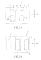
- FIG. 13 is a schematic side view of a focus enhancing electromagnetic wave propagating device according to the thirteenth preferred embodiment of the present invention in the X-Y plane;
- FIG. 14 is a schematic side view of a focus enhancing electromagnetic wave propagating device according to the fourteenth preferred embodiment of the present invention in the X-Y plane;
- FIG. 15 is a schematic top view of the focus enhancing electromagnetic wave propagating device according to the first implementation of the first preferred embodiment in a Y-Z plane;
- FIG. 16 is a schematic top view of the focus enhancing electromagnetic wave propagating device according to the second implementation of the first preferred embodiment in a Y-Z plane;
- FIG. 17 a is a schematic top view of the focus enhancing electromagnetic wave propagating device according to the first implementation of the fifteenth preferred embodiment of the present invention in the Y-Z plane;
- FIG. 17 b is a schematic top view of the focus enhancing electromagnetic wave propagating device according to the second implementation of the fifteenth preferred embodiment of the present invention in the Y-Z plane;
- FIG. 17 c is a schematic top view of the focus enhancing electromagnetic wave propagating device according to the third implementation of the fifteenth preferred embodiment of the present invention in the Y-Z plane;
- FIG. 17 d is a schematic top view of the focus enhancing electromagnetic wave propagating device according to the fourth implementation of the fifteenth preferred embodiment of the present invention in the Y-Z plane;
- FIG. 18 is a schematic top view of the focus enhancing electromagnetic wave propagating device according to the sixteenth preferred embodiment of the present invention in the Y-Z plane;
- FIG. 19 a is a schematic top view of the focus enhancing electromagnetic wave propagating device according to the first implementation of the seventeenth preferred embodiment of the present invention in the Y-Z plane;
- FIG. 19 b is a schematic top view of the focus enhancing electromagnetic wave propagating device according to the second implementation of the seventeenth preferred embodiment of the present invention in the Y-Z plane;
- FIG. 20 is a schematic top view of the focus enhancing electromagnetic wave propagating device according to the eighteenth preferred embodiment of the present invention in the Y-Z plane;
- FIG. 21 is a schematic top view of the focus enhancing electromagnetic wave propagating device according to the nineteenth preferred embodiment of the present invention in the Y-Z plane;
- FIG. 22 is a schematic top view of the focus enhancing electromagnetic wave propagating device according to the twentieth preferred embodiment of the present invention in the Y-Z plane;
- FIG. 23 a is a schematic top view of the focus enhancing electromagnetic wave propagating device according to the first implementation of the twenty-first preferred embodiment of the present invention in the Y-Z plane;
- FIG. 23 b is a schematic top view of the focus enhancing electromagnetic wave propagating device according to the second implementation of the twenty-first preferred embodiment of the present invention in the Y-Z plane;
- FIG. 24 is a schematic top view of the focus enhancing electromagnetic wave propagating device according to the twenty-second preferred embodiment of the present invention in the Y-Z plane;
- FIG. 25 is a schematic top view of the focus enhancing electromagnetic wave propagating device according to the twenty-third preferred embodiment of the present invention in the Y-Z plane;
- FIG. 26 is a schematic top view of the focus enhancing electromagnetic wave propagating device according to the twenty-fourth preferred embodiment of the present invention in the Y-Z plane;
- FIG. 27 is a schematic top view of the focus enhancing electromagnetic wave propagating device according to the twenty-fifth preferred embodiment of the present invention in the Y-Z plane;
- FIG. 28 is a schematic top view of the focus enhancing electromagnetic wave propagating device according to the twenty-sixth preferred embodiment of the present invention in the Y-Z plane;
- FIG. 29 is a schematic top view of the focus enhancing electromagnetic wave propagating device according to the twenty-seventh preferred embodiment of the present invention in the Y-Z plane;
- FIG. 30 is a schematic top view of the focus enhancing electromagnetic wave propagating device according to the twenty-eighth preferred embodiment of the present invention in the Y-Z plane;
- FIG. 31 is a schematic top view of the focus enhancing electromagnetic wave propagating device according to the twenty-ninth preferred embodiment of the present invention in the Y-Z plane;
- FIG. 32 is a schematic top view of the focus enhancing electromagnetic wave propagating device according to the thirtieth preferred embodiment of the present invention in the Y-Z plane.
- a light spot generator includes a wave emanating block 1 , from which an electromagnetic wave having a wavelength ( ⁇ ) propagates in a wave-propagating direction, and a focus enhancing electromagnetic wave propagating device 2 .
- the electromagnetic wave propagating device 2 includes a main body 3 that has surfaces capable of blocking propagation of the electromagnetic wave, and that includes an incident side 31 and an exit side 32 opposite to the incident side 31 in the wave-propagating direction.
- the main body 3 is formed with a main wave-propagating structure 4 that extends from the incident side 31 to the exit side 32 , that defines a central axis (X), and that is adapted to allow the electromagnetic wave to propagate from the wave emanating block 1 therethrough for focusing into a focusing light spot (P).
- a main wave-propagating structure 4 that extends from the incident side 31 to the exit side 32 , that defines a central axis (X), and that is adapted to allow the electromagnetic wave to propagate from the wave emanating block 1 therethrough for focusing into a focusing light spot (P).
- the main body 3 is further formed with an auxiliary wave-propagating channel 5 that extends from the incident side 31 to the exit side 32 , that has an inner dimension not greater than the wavelength ( ⁇ ) of the electromagnetic wave, and that defines a channel axis (C), which is parallel to the central axis (X).
- the main wave-propagating structure 4 has an incident end 42 at the incident side 31 of the main body 3 , and an exit end 43 at the exit side 32 of the main body 3 .
- the auxiliary wave-propagating channel 5 has an incident opening 51 at the incident side 31 of the main body 3 , an exit opening 52 at the exit side 32 of the main body 3 , and an inner portion extending between the incident opening 51 and the exit opening 52 , and defining the channel axis (C).
- the auxiliary wave-propagating channel 5 is adapted to allow the electromagnetic wave to propagate from the wave emanating block 1 therethrough toward the focusing light spot (P).
- a phase difference ( ⁇ ) is required to be present between the electromagnetic wave after traveling through the main wave-propagating structure 4 at the exit end 43 of the main wave-propagating structure 4 and the electromagnetic wave after traveling through the auxiliary wave-propagating channel 5 at the exit opening 52 of the auxiliary wave-propagating channel 5 , such that constructive interference is generated at the focusing light spot (P) between the electromagnetic wave traveling through the main wave-propagating structure 4 and the electromagnetic wave traveling through the auxiliary wave-propagating channel 5 .
- luminance intensity at an area proximate to and including the focusing light spot (P) is enhanced.
- FWHM full-width-half-maximum
- the required phase difference ( ⁇ ) is a function of a distance between the focusing light spot (P) and the exit end 43 of the main wave-propagating structure 4 , a distance between the focusing light spot (P) and the exit opening 52 of the auxiliary wave-propagating channel 5 , velocities of the electromagnetic wave after traveling through each of the main wave-propagating structure 4 and the auxiliary wave-propagating channel 5 , and angular frequencies of the electromagnetic wave after traveling through each of the main wave-propagating structure 4 and the auxiliary wave-propagating channel 5 .
- the distance between the exit opening 52 of the auxiliary wave-propagating channel 5 and the focusing light spot (P) ranges between the values represented by the following Equation 1 and Equation 2:
- r A + v A ⁇ A ⁇ ( ⁇ + ⁇ 2 + ⁇ M v M ⁇ r M ) ( Equation ⁇ ⁇ 1 )
- r A - v A ⁇ A ⁇ ( ⁇ - ⁇ 2 + ⁇ M v M ⁇ r M ) ( Equation ⁇ ⁇ 2 )
- r A + is one of a maximum value and a minimum value of the distance between the exit opening 52 of the auxiliary wave-propagating channel 5 and the focusing light spot (P)
- r A ⁇ is the other one of a maximum value and a minimum value of the distance between the exit opening 52 of the auxiliary wave-propagating channel 5 and the focusing light spot (P)
- v A is the velocity of the electromagnetic wave after traveling through the auxiliary wave-propagating channel 5
- ⁇ A is the angular frequency of the electromagnetic wave after traveling through the auxiliary wave-propagating channel 5
- ⁇ is the phase difference between the electromagnetic wave after traveling through the
- the main wave-propagating structure 4 is formed with a main wave-propagating channel 41 , which extends from the incident side 31 to the exit side 32 of the main body 3 , which has an exit opening 43 (given the same reference numeral as the exit end) at the exit end 43 of the main wave-propagating structure 4 , and which defines a central line (D) that coincides with the central axis (X).
- the channel axis (C) of the auxiliary wave-propagating channel 5 is spaced apart from the central line (D) of the main wave-propagating channel 41 , or the central axis (X) of the main wave-propagating structure 4 , along a first axis (Y).
- the position of the focusing light spot (P) is slightly adjusted.
- the focusing light spot (P) would originally be disposed along the central axis (X) of the main wave-propagating structure 4 when the main body 3 is not formed with the auxiliary wave-propagating channel 5 .
- the focusing light spot (P) is shifted toward the auxiliary wave-propagating channel 5 along the first axis (Y).
- auxiliary wave-propagating channel 5 By forming the auxiliary wave-propagating channel 5 in the main body 3 with the inner dimension not greater than the wavelength ( ⁇ ) of the electromagnetic wave, surface plasma waves (denoted by (A)) and near-fields (denoted by (N)) near a surface of the main body 3 are excited by the electromagnetic wave (denoted by (B)) passing through the auxiliary wave-propagating channel 5 to move along the surface of the main body 3 within the auxiliary wave-propagating channel 5 , and create a guiding effect to guide the electromagnetic wave (B) to travel toward the direction of the flow of the surface plasma waves (A) after propagating through the auxiliary wave-propagating channel 5 .
- a portion of the electromagnetic wave (B) traveling out of the auxiliary wave-propagating channel 5 is traveling more toward the central axis (X) of the main wave-propagating structure 4 , and contributes to enhance the luminance intensity at the area proximate to and including the focusing light spot (P).
- phase difference ⁇ between the electromagnetic wave after traveling through the main wave-propagating channel 41 at the exit opening 43 of the main wave-propagating channel 41 and the electromagnetic wave after traveling through the auxiliary wave-propagating channel 5 at the exit opening 52 of the auxiliary wave-propagating channel 5 is also affected by other factors, such as a distance between the channel axis (C) of the auxiliary wave-propagating channel 5 and the central axis (X) of the main wave-propagating structure 4 , a shape of the auxiliary wave-propagating channel 5 (as will be discussed later), a configuration of the main wave-propagating structure 4 , and a material inside the auxiliary wave-propagating channel 5 .
- These factors and the aforementioned Equations 1 and 2 cooperate to create complex physics mechanism for the enhancement of the luminance intensity and the reduction of size of the focusing light spot (P).
- the focus enhancing electromagnetic wave propagating device 2 ′ differs from the first implementation of the first preferred embodiment in that the main body 3 ′ is formed with two of the auxiliary wave-propagating channels 5 , and that the main wave-propagating structure 4 is flanked by the auxiliary wave-propagating channels 5 along the first axis (Y).
- the auxiliary wave-propagating channels 5 are disposed symmetrically relative to the central axis (X) of the main wave-propagating structure 4 .
- the focus enhancing electromagnetic wave propagating device 2 a differs from the focus enhancing electromagnetic wave propagating device 2 of the first preferred embodiment in that the exit opening 52 a of the auxiliary wave-propagating channel 5 a is asymmetrical about the channel axis (C) in a plane defined by the central axis (X) and the first axis (Y).
- the plane defined by the central axis (X) and the first axis (Y) is hereinafter referred to as the X-Y plane.
- the exit opening 52 a has first and second halves 521 , 522 about the channel axis (C) in the plane defined by the central axis (X) and the first axis (Y).
- the first and second halves 521 , 522 are respectively proximate to and distal from the central axis (X) of the main wave-propagating structure 4 .
- the first half 521 has a dimension greater than that of the second half 522 , such that the main body 3 a recedes from the auxiliary wave-propagating channel 5 a at the exit opening 52 a toward the central axis (X) of the main wave-propagating structure 4 .
- a surface plasma wave (denoted by (A)) excited by the electromagnetic wave (denoted by (B)) passing through the auxiliary wave-propagating channel 5 a moves along the receding structure (A)).
- a near-field wave (denoted by (N)) is generated corresponding to the surface plasma wave (A) to move along the surface of the main body 3 a at the receding structure.
- the surface plasma wave (A) and the near-field wave (N) cooperate to create a greater guiding effect, such that the electromagnetic wave traveling through the auxiliary wave-propagating channel 5 a is guided more toward the central axis (X) of the main wave-propagating structure 4 while the intensity of such electromagnetic wave is still high.
- propagation path of the electromagnetic wave (B) traveling through the auxiliary wave-propagating channel 5 a bends toward the central axis (X) of the main wave-propagating structure 4 , and contributes to enhance the luminance intensity at the area proximate to and including the focusing light spot (P) with an effect even greater than that of the first implementation shown in FIG. 1 a.
- the focus enhancing electromagnetic wave propagating device 2 a ′ differs from the first implementation of the second preferred embodiment in that the main body 3 a ′ is formed with two of the auxiliary wave-propagating channels 5 a , and that the main wave-propagating structure 4 is flanked by the auxiliary wave-propagating channels 5 a along the first axis (Y).
- the auxiliary wave-propagating channels 5 a are disposed symmetrically relative to the central axis (X) of the main wave-propagating structure 4 .
- the focus enhancing electromagnetic wave propagating device 2 b differs from the focus enhancing electromagnetic wave propagating device 2 of the first preferred embodiment in that the main wave-propagating structure 4 b of the second preferred embodiment is formed with two of the main wave-propagating channels 41 , each of which defines a central line (D) that is parallel to and spaced apart from the central axis (X) of the main wave-propagating structure 4 b , that the auxiliary wave-propagating channel 5 b of the second preferred embodiment is flanked by the main wave-propagating channels 41 , and that the focus enhancing electromagnetic wave propagating device 2 b further includes a light-transmissible dielectric 6 that is filled in the auxiliary wave-propagating channel 5 b .
- the channel axis (C) of the auxiliary wave-propagating channel 5 b is spaced apart from the central line (D) of each of the main wave-propagating channels 41 along the first axis (Y), and coincides with the central axis (X) of the main wave-propagating structure 4 b .
- the light-transmissible dielectric 6 may also be filled in each of the main wave-propagating channels 41 of the main wave-propagating structure 4 according to other embodiments of the present invention.
- the focus enhancing electromagnetic wave propagating device 2 b may include two different types of light-transmissible dielectrics that are respectively filled in each of the main wave-propagating channels 41 and the auxiliary wave-propagating channel 5 b .
- each of the main wave-propagating channels 41 may be filled with a first light-transmissible dielectric (e.g., air), while the auxiliary wave-propagating channel 5 b may be filled with a second light-transmissible dielectric (e.g., glass).
- a first light-transmissible dielectric e.g., air
- a second light-transmissible dielectric e.g., glass
- the focus enhancing electromagnetic wave propagating device 2 c differs from the focus enhancing electromagnetic wave propagating device 2 b of the third preferred embodiment in that the exit openings 43 c of the main wave-propagating channels 41 c are in direct spatial communication with each other along the first axis (Y).
- the focus enhancing electromagnetic wave propagating device 2 d differs from the focus enhancing electromagnetic wave propagating device 2 of the first preferred embodiment in that the main wave-propagating structure 4 d is formed with two of the main wave-propagating channels 41 d , each of which defines a central line (D) parallel to the central axis (X).
- the exit openings 43 d of each of the main wave-propagating channels 41 d is asymmetrical relative to the central line (D) thereof in the plane defined by the central axis (X) and the first axis (Y).
- the auxiliary wave-propagating channel 5 is disposed proximate to one of the main wave-propagating channels 41 d .
- each of the main wave-propagating channels 41 d has first and second halves 431 , 432 about the central line (D) in the plane defined by the central axis (X) and the first axis (Y).
- the first and second halves 431 , 432 are respectively proximate to and distal from the central axis (X) of the main wave-propagating structure 4 .
- the first half 431 has a dimension greater than that of the second half 432 , such that the main body 3 a recedes from each of the main wave-propagating channels 41 d at the exit opening 43 d toward the central axis (X) of the main wave-propagating structure 4 d.
- the first and second halves 521 e , 522 e are respectively proximate to and distal from the central line (D) of the proximate one of the main wave-propagating channels 41 .
- the first half 521 e has a dimension greater than that of the second half 522 e.
- the focus enhancing electromagnetic wave propagating device 2 f differs from the focus enhancing electromagnetic wave propagating device 2 d of the fifth preferred embodiment in that the main body 3 f of the seventh preferred embodiment is formed with two of the auxiliary wave-propagating channels 5 that flank the main wave-propagating structure 4 d .
- the channel axis (C) of each of the auxiliary wave-propagating channels 5 is disposed proximate to the central line (D) of a respective one of the main wave-propagating channels 41 d , and is spaced apart from the central line (D) of the respective one of the main wave-propagating channels 41 d by the spacing distance along the first axis (Y).
- the focus enhancing electromagnetic wave propagating device 2 g differs from the focus enhancing electromagnetic wave propagating device 2 f of the seventh preferred embodiment in that the main body 3 g of the eighth preferred embodiment is further formed with an additional auxiliary wave-propagating channel 5 that is interposed between the main wave-propagating channels 41 d (in other words, the main body 3 g of the eighth preferred embodiment is formed with a total of three auxiliary wave-propagating channels 5 ), and that the focus enhancing electromagnetic wave propagating 2 g a device further includes light-transmissible dielectric 6 that is filled in said additional one of the auxiliary wave-propagating channels 5 .
- the channel axis (C) of said additional one of the auxiliary wave-propagating channels 5 coincides with the central axis (X) of the main wave-propagating structure 4 d.
- the first and second halves 521 h , 522 h are respectively proximate to and distal from the central line (D) of the respective one of the main wave-propagating channels 41 d .
- the first half 521 h has a dimension greater than that of the second half 522 h.
- the focus enhancing electromagnetic wave propagating device 2 i differs from the focus enhancing electromagnetic wave propagating device 2 f of the seventh preferred embodiment in that the exit openings 43 i of the main wave-propagating channels 41 i of the main wave-propagating structure 4 i are in direct spatial communication with each other along the first axis (Y).
- the focus enhancing electromagnetic wave propagating device 2 j differs from the focus enhancing electromagnetic wave propagating device 2 i of the tenth preferred embodiment in that there is only one auxiliary wave-propagating channel 5 in the eleventh preferred embodiment, and the auxiliary wave-propagating channel 5 is disposed proximate to one of the main wave-propagating channels 41 i.
- the focus enhancing electromagnetic wave propagating device 2 k differs from the focus enhancing electromagnetic wave propagating device 2 e of the sixth preferred embodiment (as shown in FIG. 6 ) in that the exit openings 43 i of the main wave-propagating channels 41 i of the main wave-propagating structure 4 i of the twelfth preferred embodiment are in direct spatial communication with each other along the first axis (Y).
- the focus enhancing electromagnetic wave propagating device 2 m differs from the focus enhancing electromagnetic wave propagating device 2 h of the ninth preferred embodiment (as shown in FIG. 9 ) in that the exit openings 43 i of the main wave-propagating channels 41 i of the main wave-propagating structure 4 i of the thirteenth preferred embodiment are in direct spatial communication with each other along the first axis (Y).
- the focus enhancing electromagnetic wave propagating device 2 n differs from the focus enhancing electromagnetic wave propagating device 2 i of the tenth preferred embodiment (as shown in FIG. 10 ) in that the exit openings 43 i of the main wave-propagating channels 41 i of the main wave-propagating structure 4 i of the fourteenth preferred embodiment are in direct spatial communication with each other along the first axis (Y).
- FIGS. 1 a ⁇ 1 b , 2 a ⁇ 2 b , and 3 ⁇ 14 are schematic side views of the focus enhancing electromagnetic wave propagating devices according to various embodiments of the present invention, the configurations and shapes shown therein are also representative of the cross-sectional profiles of the focus enhancing electromagnetic wave propagating devices in the Z-Y plane according to various embodiments of the present invention.
- FIG. 15 is a schematic top view of the focus enhancing electromagnetic propagating device 2 according to the first implementation of the first preferred embodiment (whose sectional view in the X-Y plane is shown in FIG. 1 a ) in another dimension.
- the incident opening 42 of the main wave-propagating channel 41 has a shape in a plane defined by the first axis (Y) and a second axis (Z) orthogonal to the first axis (Y) and the central axis (X) that is substantially the same as that of the incident opening 51 of the auxiliary wave-propagating channel 5 .
- the shapes of the incident openings 42 , 51 are shown to be rectangular.
- the plane defined by the first axis (Y) and a second axis (Z) is hereinafter referred to as the Y-Z plane.
- FIG. 16 is a schematic top view of the focus enhancing electromagnetic propagating device 2 ′ according to the second implementation of the first preferred embodiment (whose sectional view in the X-Y plane is shown in FIG. 1 b ) in another dimension.
- the incident openings 42 , 51 of the main wave-propagating channel 41 and the auxiliary wave-propagating channels 5 are shown to be rectangular in shape.
- the shapes of the incident openings 42 , 51 p of the main wave-propagating channel 41 and the auxiliary wave-propagating channel 5 p in the Y-Z plane are substantially different, where the incident opening 42 of the main wave-propagating channel 41 is rectangular in shape, and the incident opening 51 p of the auxiliary wave-propagating channel 5 p has an arcuate shape in the Y-Z plane that curves about the central axis (X) of the main wave-propagating structure 4 .
- the focus enhancing electromagnetic wave propagating device 2 p ′ differs from the focus enhancing electromagnetic wave propagating device 2 p of the first implementation of the fifteenth preferred embodiment in that the main body 3 p ′ of the second implementation is formed with two of the auxiliary wave-propagating channels 5 p , and that the main wave-propagating structure 4 is flanked by the auxiliary wave-propagating channels 5 p along the first axis (Y).
- the auxiliary wave-propagating channels 5 p are disposed symmetrically relative to the central axis (X) of the main wave-propagating structure 4 .
- the focus enhancing electromagnetic wave propagating device 2 p ′′ according to the third implementation of the fifteenth preferred embodiment of the present invention differs from the focus enhancing electromagnetic wave propagating device 2 p ′ of the second implementation of the fifteenth preferred embodiment in that the incident openings 51 p ′′ of the auxiliary wave-propagating channels 5 p ′′ of the third implementation have a shape in the Y-Z plane of a segment of an annular ring that curves about the central axis (X) of the main wave-propagating structure 4 .
- the focus enhancing electromagnetic wave propagating device 2 p ′′′ differs from the third implementation of the fifteenth preferred embodiment in that the incident openings 51 p ′′′ of the auxiliary wave-propagating channels 5 p ′′′ of the fourth implementation have a shape in the Y-Z plane of a segment of an annular ring that curves away from the central axis (X) of the main wave-propagating structure 4 .
- the shapes of the incident openings 42 , 51 of the main wave-propagating channels 41 and the auxiliary wave-propagating channels 5 in the Y-Z plane are substantially the same, i.e., rectangular, and are arranged symmetrically relative to the central axis (X) of the main wave-propagating structure 4 q .
- position of the focusing light spot (P) (not shown in this figure) along the first axis (Y) is substantially unaffected by the auxiliary wave-propagating channels 5 , and is therefore substantially along the central axis (X) of the main wave-propagating structure 4 q .
- the incident openings 51 of the auxiliary wave-propagating channels 5 are shown to be longer in the direction of the second axis (Z) than the incident openings 42 of the main wave-propagating channels 4 , the present invention is not limited to the relative dimensions of the incident openings 51 , 42 in this particular aspect.
- the shapes of the incident openings 42 r , 51 of the main wave-propagating channels 41 r and the auxiliary wave-propagating channels 5 in the Y-Z plane are substantially different.
- the incident openings 42 r of the main wave-propagating channels 41 r are connected to each other, i.e., they are in direct spatial communication with each other, and cooperate to form an annular shape.
- the incident openings 51 of the auxiliary wave-propagating channels 5 are disposed symmetrically in the direction along the first axis (Y) relative to the central axis (X) of the main wave-propagating structure 4 r .
- the advantage of having an overall annular wave-propagating channel in the main wave-propagating structure 4 r is that the annular shape contributes to provide even effective areas for electromagnetic waves with different polarizations during propagation.
- the focus enhancing electromagnetic wave propagating device 2 r ′ differs from the focus enhancing electromagnetic wave propagating device 2 r of the first implementation of the seventeenth preferred embodiment in that the main body 3 r ′ of the second implementation of the seventeenth preferred embodiment is provided with four of the auxiliary wave-propagating channels 5 that have rectangular incident openings 51 in the Y-Z plane.
- the rectangular shapes of a first pair of opposing auxiliary wave-propagating channels 5 extend in directions along the first axis (Y), and the rectangular shapes of a second pair of opposing auxiliary wave-propagating channels 5 extend in directions along the second axis (Z).
- the formation of the two opposite pairs of auxiliary wave-propagating channels 5 facilitates enhancement of the luminance intensity at the focusing light spot (P) (not shown in this figure) when the electromagnetic wave is polarized in two or more different directions.
- the shapes of the incident openings 42 , 51 p of the main wave-propagating channels 41 and the auxiliary wave-propagating channels 5 p in the Y-Z plane are substantially different, and are arranged symmetrically relative to the central axis (X) of the main wave-propagating structure 4 q .
- the incident openings 51 p of the auxiliary wave-propagating channels 5 p are curved toward the central axis (X) of the main wave-propagating structure 4 q .
- the curved shape of the incident openings 51 p also takes into account the varying polarization of the electromagnetic waves to be propagated therethrough.
- the shapes of the incident openings 51 t of the auxiliary wave-propagating channels 5 t in the Y-Z plane are essentially segments of an overall annular shape that is centered at the central axis (X) of the main wave-propagating structure 4 q .
- the incident openings 51 u of the auxiliary wave-propagating channels 5 u are connected to each other in the Y-Z plane so as to form an overall annular shape.
- the focus enhancing electromagnetic propagating device 2 v is basically a modification of the first implementation of the seventeenth preferred embodiment (as shown in FIG. 19 a ) and the eighteenth preferred embodiment (as shown in FIG. 20 ), where the incident openings 42 r of the main wave-propagating channels 41 r are connected to each other, i.e., they are in direct spatial communication with each other so as to form an annular shape, and where the incident openings 51 p ′′ of the auxiliary wave-propagating channels 5 p ′′ are curved toward the central axis (X) of the main wave-propagating structure 4 r.
- the focus enhancing electromagnetic propagating device 2 v ′ differs from the focus enhancing electromagnetic propagating device 2 v of the first implementation of the twenty-first preferred embodiment in that the main body 3 v ′ of the second implementation of the twenty-first preferred embodiment is provided with four of the auxiliary wave-propagating channels 5 p ′′.
- the formation of the two opposite pairs of the auxiliary wave-propagating channels 5 p ′′ facilitates enhancement of the luminance intensity at the focusing light spot (P) (not shown in this figure) when the electromagnetic wave is polarized in two different directions.
- the incident openings 51 p ′′ of the auxiliary wave-propagating channels 5 p ′′ may be connected to each other to form an overall annular shape, as illustrated in FIG. 24 according to the twenty-second preferred embodiment of the present invention.
- the annular shape formed by the connected incident openings 51 u of the auxiliary wave-propagating channels 5 u surrounds the annular shape formed by the incident openings 42 r (as shown in FIG. 19 a ) of the main wave-propagating channels 41 r (as shown in FIG. 19 a ).
- the main body may be further formed with another set of annularly-connected auxiliary wave-propagating channels to surround the annular shape formed by the incident openings of the main wave-propagating channels and the annular shape formed by the incident openings of the original set of auxiliary wave-propagating channels.
- the focus enhancing electromagnetic wave propagating device 2 w differs from the twenty-second preferred embodiment shown in FIG. 24 in that the main wave-propagating structure 4 w is formed with a first pair of main wave-propagating channels 41 w whose incident openings 42 w extend in a direction along the first axis (Y), and a second pair of main wave-propagating channels 41 w whose incident openings 42 w extend in a direction along the second axis (Z), and intersect the incident openings 42 w extending in the direction along the first axis (Y).
- This particular configuration creates a desirable effective area when the electromagnetic wave that emanates from the wave emanating block 1 (as shown in FIG.
- the focus enhancing electromagnetic wave propagating device 2 x essentially combines the two opposite pairs of auxiliary wave-propagating channels 5 according to the second implementation of the seventeenth preferred embodiment (as shown in FIG. 19 b ) and the main wave-propagating structure 4 w according to the twenty-third preferred embodiment (as shown in FIG. 25 ).
- the focus enhancing electromagnetic wave propagating device 2 y differs from the focus enhancing electromagnetic wave propagating device 2 q of the sixteenth preferred embodiment in that the main wave-propagating structure 4 y of the focus enhancing electromagnetic wave propagating device 2 y is formed with two main wave-propagating channels 41 y , the incident opening 42 y of each of which has an arcuate shape that curves toward the central axis (X) of the main wave-propagating structure 4 y in the Y-Z plane.
- the arcuate shapes are connected at two tips thereof such that the incident openings 42 y of the main wave-propagating channels 41 y cooperate to form the main body 3 y with an eye-shaped configuration in the Y-Z plane.
- the focus enhancing electromagnetic wave propagating device 2 y ′ essentially combines the two auxiliary wave-propagating channels 5 p ′′ according to the eighteenth preferred embodiment (as shown in FIG. 20 ) and the main wave-propagating structure 4 y according to the twenty-fifth preferred embodiment (as shown in FIG. 27 ).
- the focus enhancing electromagnetic wave propagating device 2 y ′′ essentially combines the main wave-propagating structure 4 y according to the twenty-fifth preferred embodiment (as shown in FIG. 27 ) and the auxiliary wave-propagating channels 5 u whose incident openings 51 u cooperate to form an overall annular shape according to the twentieth preferred embodiment (as shown in FIG. 22 ).
- the focus enhancing electromagnetic wave propagating device 2 z essentially combines the main wave-propagating structure 4 q according to the sixteenth preferred embodiment (as shown in FIG. 18 ) and the auxiliary wave-propagating channels 5 p according to the second implementation of the fifteenth preferred embodiment (as shown in FIG. 17 b ).
- the arcuate shapes of the incident openings 51 p of the auxiliary wave-propagating channels 5 p are connected to each other in this embodiment such that the incident openings 51 p cooperate to form the main body 3 z with an eye-shaped configuration in the Y-Z plane.
- the focus enhancing electromagnetic wave propagating device 2 z ′ essentially combines the main wave-propagating structure 4 y according to the twenty-fifth preferred embodiment (as shown in FIG. 27 ) and the configuration of the auxiliary wave-propagating channels 5 p according to the twenty-eighth preferred embodiment (as shown in FIG. 30 ).
- the focus enhancing electromagnetic wave propagating device 2 z ′′ differs from the twenty-ninth preferred embodiment in that the incident openings 42 z ′′, 51 z ′′ of the main wave-propagating channels 41 z ′′ and the auxiliary wave-propagating channels 5 z ′′ are in direct spatial communication with each other in the Y-Z plane.
- FIGS. 15 ⁇ 16 , 17 a ⁇ 17 d , 18 , 19 a ⁇ 19 b , 20 ⁇ 22 , 23 a ⁇ 23 b , and 24 ⁇ 32 are schematic top views of the focus enhancing electromagnetic wave propagating devices according to various embodiments of the present invention, the shapes shown therein are also representative of the cross-sectional profiles of the focus enhancing electromagnetic wave propagating devices in the Y-Z plane according to various embodiments of the present invention.
- auxiliary wave-propagating channels 5 may be formed repeatedly about the central axis (X) of the main wave-propagating structure 4 in other embodiments of the present invention.
- the cross-sectional of the profile auxiliary wave-propagating channels 5 in the Y-Z plane may be two concentric circles of different radii with centers at the central axis (X) of the main wave-propagating structure 4 and encircling the main wave-propagating structure 4 , which can itself have varying profiles in the Y-Z plane.
- the present invention achieves the effect of enhancing the luminance intensity of a focusing light spot that is formed by an electromagnetic wave traveling through a main wave-propagating structure by providing auxiliary wave-propagating channel(s) to allow for the electromagnetic wave to propagate therethrough and to guide the electromagnetic wave traveling therethrough toward the focusing light spot and to create constructive interference between the electromagnetic wave traveling through the main wave-propagating structure and the electromagnetic wave traveling through the auxiliary wave-propagating channel(s).
- a full-width-half-maximum (FWHM) spot size of the focusing light spot is also reduced.
- the present invention also achieves the effect of adjusting the position of the focusing light spot by providing the auxiliary wave-propagating channel(s) in the main body asymmetrically relative to a central axis of the main wave-propagating structure.
- main wave-propagating channels are shown to be larger in dimension than the auxiliary wave-propagating channels in the accompanying drawings, the present invention is not limited to such configurations.
- the focus enhancing electromagnetic wave propagating device may work under all kinds of environments and media, including vacuum, air, water, oil, glass, silicon, dielectric, etc.
Abstract
Description
where rA + is one of a maximum value and a minimum value of the distance between the exit opening of the auxiliary wave-propagating channel and the focusing light spot, rA − is the other one of a maximum value and a minimum value of the distance between the exit opening of the auxiliary wave-propagating channel and the focusing light spot, vA is the velocity of the electromagnetic wave after traveling through the auxiliary wave-propagating channel, ωA is the angular frequency of the electromagnetic wave after traveling through the auxiliary wave-propagating channel, Δφ is the phase difference between the electromagnetic wave after traveling through the main wave-propagating structure at the exit end of the main wave-propagating structure and the electromagnetic wave after traveling through the auxiliary wave-propagating channel at the exit opening of the auxiliary wave-propagating channel, ωM is the angular frequency of the electromagnetic wave after traveling through the main wave-propagating structure, vM is the velocity of the electromagnetic wave after traveling through the main wave-propagating structure, and rM is the distance between the exit end of the main wave-propagating structure and the focusing light spot.
where rA + is one of a maximum value and a minimum value of the distance between the exit opening 52 of the auxiliary wave-propagating
Claims (22)
Priority Applications (1)
| Application Number | Priority Date | Filing Date | Title |
|---|---|---|---|
| US12/629,725 US8078027B2 (en) | 2008-12-03 | 2009-12-02 | Focus enhancing electromagnetic wave propagating device |
Applications Claiming Priority (2)
| Application Number | Priority Date | Filing Date | Title |
|---|---|---|---|
| US11949308P | 2008-12-03 | 2008-12-03 | |
| US12/629,725 US8078027B2 (en) | 2008-12-03 | 2009-12-02 | Focus enhancing electromagnetic wave propagating device |
Publications (2)
| Publication Number | Publication Date |
|---|---|
| US20100134890A1 US20100134890A1 (en) | 2010-06-03 |
| US8078027B2 true US8078027B2 (en) | 2011-12-13 |
Family
ID=42222587
Family Applications (1)
| Application Number | Title | Priority Date | Filing Date |
|---|---|---|---|
| US12/629,725 Active 2030-06-07 US8078027B2 (en) | 2008-12-03 | 2009-12-02 | Focus enhancing electromagnetic wave propagating device |
Country Status (2)
| Country | Link |
|---|---|
| US (1) | US8078027B2 (en) |
| TW (1) | TWI407149B (en) |
Families Citing this family (2)
| Publication number | Priority date | Publication date | Assignee | Title |
|---|---|---|---|---|
| EP3312647B1 (en) * | 2015-07-16 | 2021-02-03 | Huawei Technologies Co., Ltd. | Polarization mode converter |
| EP3671310A1 (en) * | 2018-12-18 | 2020-06-24 | Thomson Licensing | Optical manipulation apparatus for trapping or moving micro or nanoparticles |
Citations (2)
| Publication number | Priority date | Publication date | Assignee | Title |
|---|---|---|---|---|
| US6317536B1 (en) * | 1997-06-18 | 2001-11-13 | Corning Incorporated | Phased fiber array for multiplexing and demultiplexing |
| US6917736B1 (en) * | 2002-05-09 | 2005-07-12 | Purdue Research Foundation | Method of increasing number of allowable channels in dense wavelength division multiplexing |
Family Cites Families (1)
| Publication number | Priority date | Publication date | Assignee | Title |
|---|---|---|---|---|
| US20060272418A1 (en) * | 2005-06-03 | 2006-12-07 | Brown University | Opto-acoustic methods and apparatus for perfoming high resolution acoustic imaging and other sample probing and modification operations |
-
2009
- 2009-12-02 US US12/629,725 patent/US8078027B2/en active Active
- 2009-12-03 TW TW098141355A patent/TWI407149B/en active
Patent Citations (2)
| Publication number | Priority date | Publication date | Assignee | Title |
|---|---|---|---|---|
| US6317536B1 (en) * | 1997-06-18 | 2001-11-13 | Corning Incorporated | Phased fiber array for multiplexing and demultiplexing |
| US6917736B1 (en) * | 2002-05-09 | 2005-07-12 | Purdue Research Foundation | Method of increasing number of allowable channels in dense wavelength division multiplexing |
Also Published As
| Publication number | Publication date |
|---|---|
| TW201042286A (en) | 2010-12-01 |
| US20100134890A1 (en) | 2010-06-03 |
| TWI407149B (en) | 2013-09-01 |
Similar Documents
| Publication | Publication Date | Title |
|---|---|---|
| Quimby | Photonics and lasers: an introduction | |
| US6934429B2 (en) | Optical waveguide board and optical module | |
| US8755661B2 (en) | Electromagnetic wave propagating structure | |
| US10992104B2 (en) | Dual layer grating coupler | |
| CN104090332B (en) | Focal length, tightly focused surface phasmon lens under a kind of radial polarisation light | |
| TWI652513B (en) | Optical device capable of steering incident electromagnetic waves | |
| EP3064986B1 (en) | Laser-beam synthesis device | |
| US20160011375A1 (en) | Multi-Axis Graded-Index Photonic Coupling | |
| US20170082800A1 (en) | Optical Apparatus | |
| US8078027B2 (en) | Focus enhancing electromagnetic wave propagating device | |
| US10551563B2 (en) | Optical guide comprising a bend with a pseudo-index gradient | |
| CN105659134A (en) | Detector device | |
| US20220043192A1 (en) | Device for radiating at least one outgoing electromagnetic wave when illuminated by an incoming electromagnetic wave | |
| Caer et al. | Large group-index bandwidth product empty core slow light photonic crystal waveguides for hybrid silicon photonics | |
| US10598854B2 (en) | Micro optical circuit and optical mode converter | |
| US20190072717A1 (en) | Semiconductor device | |
| KR20190103978A (en) | Waveguide for plastic welding, arrangement for plastic welding, a welding method as well as a manufacturing method of a waveguide | |
| WO2016169054A1 (en) | Waveguide structure and silicon-based chip | |
| JP4296692B2 (en) | Laser beam synthesis optical system | |
| US10908355B2 (en) | Wave plate and divided prism member | |
| CN110174770B (en) | Device and method for generating on-axis multistage stable transmission Bessel light beam | |
| EP4261897A1 (en) | Light-receiving element | |
| US20230083232A1 (en) | Optical waveguide device and optical integrated circuit that includes optical waveguide device | |
| CN101359094A (en) | Electro-magnetic wave transmission structure | |
| Zhou et al. | Tailoring focal length of plasmonic lenses by phase modulation of emitted light |
Legal Events
| Date | Code | Title | Description |
|---|---|---|---|
| AS | Assignment |
Owner name: NATIONAL CHENG KUNG UNIVERSITY,TAIWAN Free format text: ASSIGNMENT OF ASSIGNORS INTEREST;ASSIGNOR:CHEN, KUAN-REN;REEL/FRAME:023596/0087 Effective date: 20091125 Owner name: NATIONAL CHENG KUNG UNIVERSITY, TAIWAN Free format text: ASSIGNMENT OF ASSIGNORS INTEREST;ASSIGNOR:CHEN, KUAN-REN;REEL/FRAME:023596/0087 Effective date: 20091125 |
|
| STCF | Information on status: patent grant |
Free format text: PATENTED CASE |
|
| FPAY | Fee payment |
Year of fee payment: 4 |
|
| MAFP | Maintenance fee payment |
Free format text: PAYMENT OF MAINTENANCE FEE, 8TH YR, SMALL ENTITY (ORIGINAL EVENT CODE: M2552); ENTITY STATUS OF PATENT OWNER: SMALL ENTITY Year of fee payment: 8 |
|
| FEPP | Fee payment procedure |
Free format text: MAINTENANCE FEE REMINDER MAILED (ORIGINAL EVENT CODE: REM.); ENTITY STATUS OF PATENT OWNER: SMALL ENTITY |
|
| FEPP | Fee payment procedure |
Free format text: 11.5 YR SURCHARGE- LATE PMT W/IN 6 MO, SMALL ENTITY (ORIGINAL EVENT CODE: M2556); ENTITY STATUS OF PATENT OWNER: SMALL ENTITY |
|
| MAFP | Maintenance fee payment |
Free format text: PAYMENT OF MAINTENANCE FEE, 12TH YR, SMALL ENTITY (ORIGINAL EVENT CODE: M2553); ENTITY STATUS OF PATENT OWNER: SMALL ENTITY Year of fee payment: 12 |