US8077995B1 - Infrared camera systems and methods using environmental information - Google Patents
Infrared camera systems and methods using environmental information Download PDFInfo
- Publication number
- US8077995B1 US8077995B1 US12/035,594 US3559408A US8077995B1 US 8077995 B1 US8077995 B1 US 8077995B1 US 3559408 A US3559408 A US 3559408A US 8077995 B1 US8077995 B1 US 8077995B1
- Authority
- US
- United States
- Prior art keywords
- infrared camera
- transformation
- infrared
- information
- environmental conditions
- Prior art date
- Legal status (The legal status is an assumption and is not a legal conclusion. Google has not performed a legal analysis and makes no representation as to the accuracy of the status listed.)
- Expired - Fee Related, expires
Links
- 230000007613 environmental effect Effects 0.000 title claims abstract description 82
- 238000000034 method Methods 0.000 title claims abstract description 21
- 230000009466 transformation Effects 0.000 claims abstract description 106
- 238000000844 transformation Methods 0.000 claims description 24
- 238000012545 processing Methods 0.000 claims description 14
- 230000008859 change Effects 0.000 claims description 7
- 238000001914 filtration Methods 0.000 claims description 5
- 230000005540 biological transmission Effects 0.000 claims description 2
- 230000001413 cellular effect Effects 0.000 claims description 2
- 230000008569 process Effects 0.000 claims description 2
- 230000001131 transforming effect Effects 0.000 claims description 2
- 230000006870 function Effects 0.000 description 6
- 238000006243 chemical reaction Methods 0.000 description 3
- 238000010586 diagram Methods 0.000 description 3
- 230000005855 radiation Effects 0.000 description 3
- 238000005457 optimization Methods 0.000 description 2
- 230000007704 transition Effects 0.000 description 2
- 239000003086 colorant Substances 0.000 description 1
- 238000004891 communication Methods 0.000 description 1
- 230000001419 dependent effect Effects 0.000 description 1
- 230000000694 effects Effects 0.000 description 1
- 238000002329 infrared spectrum Methods 0.000 description 1
- 238000009434 installation Methods 0.000 description 1
- 239000004973 liquid crystal related substance Substances 0.000 description 1
- 238000005259 measurement Methods 0.000 description 1
- 238000012986 modification Methods 0.000 description 1
- 230000004048 modification Effects 0.000 description 1
- 238000012544 monitoring process Methods 0.000 description 1
Images


Classifications
-
- G—PHYSICS
- G06—COMPUTING; CALCULATING OR COUNTING
- G06T—IMAGE DATA PROCESSING OR GENERATION, IN GENERAL
- G06T5/00—Image enhancement or restoration
- G06T5/90—Dynamic range modification of images or parts thereof
- G06T5/92—Dynamic range modification of images or parts thereof based on global image properties
-
- G—PHYSICS
- G06—COMPUTING; CALCULATING OR COUNTING
- G06T—IMAGE DATA PROCESSING OR GENERATION, IN GENERAL
- G06T5/00—Image enhancement or restoration
- G06T5/40—Image enhancement or restoration using histogram techniques
-
- H—ELECTRICITY
- H04—ELECTRIC COMMUNICATION TECHNIQUE
- H04N—PICTORIAL COMMUNICATION, e.g. TELEVISION
- H04N23/00—Cameras or camera modules comprising electronic image sensors; Control thereof
- H04N23/20—Cameras or camera modules comprising electronic image sensors; Control thereof for generating image signals from infrared radiation only
-
- H—ELECTRICITY
- H04—ELECTRIC COMMUNICATION TECHNIQUE
- H04N—PICTORIAL COMMUNICATION, e.g. TELEVISION
- H04N5/00—Details of television systems
- H04N5/30—Transforming light or analogous information into electric information
- H04N5/33—Transforming infrared radiation
-
- G—PHYSICS
- G06—COMPUTING; CALCULATING OR COUNTING
- G06T—IMAGE DATA PROCESSING OR GENERATION, IN GENERAL
- G06T2207/00—Indexing scheme for image analysis or image enhancement
- G06T2207/10—Image acquisition modality
- G06T2207/10048—Infrared image
-
- G—PHYSICS
- G06—COMPUTING; CALCULATING OR COUNTING
- G06T—IMAGE DATA PROCESSING OR GENERATION, IN GENERAL
- G06T2207/00—Indexing scheme for image analysis or image enhancement
- G06T2207/30—Subject of image; Context of image processing
- G06T2207/30248—Vehicle exterior or interior
- G06T2207/30252—Vehicle exterior; Vicinity of vehicle
Definitions
- the present invention relates generally to cameras and, more particularly, to infrared cameras and systems (e.g., for vehicle applications).
- Infrared cameras are known and utilized in a variety of applications.
- One typical configuration of an infrared camera includes a two-dimensional array of microbolometer elements used to sense infrared radiation.
- Each microbolometer element functions as a pixel to produce a two-dimensional image based on detected infrared radiation.
- the change in resistance of each microbolometer element is translated into a time-multiplexed electrical signal by circuitry known as the read out integrated circuit (ROIC).
- the combination of the ROIC and the microbolometer array is commonly known as a microbolometer focal plane array (FPA) or microbolometer infrared FPA.
- FPA microbolometer focal plane array
- FPA microbolometer infrared FPA
- a system that transforms data provided by an infrared camera based upon environmental conditions at the time the data was obtained.
- the system may be incorporated into a vehicle, with information regarding the environmental conditions provided by the vehicle's sensors and/or as determined based on the data provided by the infrared camera (e.g., using the infrared camera as an environmental sensor).
- the data from the infrared camera may be analyzed, alone or with other sensor information, to provide information as to environmental conditions, with this information used to transform the data from the infrared camera.
- an infrared camera system includes an infrared camera adapted to provide infrared image data; means for processing the infrared image data to determine environmental conditions associated with the infrared image data, wherein the processing means further applies a first transformation to the infrared image data based on the information on the environmental conditions to modify an image quality of the infrared image data and convert the image data to a lower resolution image; and means for displaying the infrared image data.
- a method of transforming infrared camera data based on environmental conditions includes processing the infrared camera data to obtain information on environmental conditions; determining a first transformation to apply to the infrared camera data based on the environmental conditions; and applying the first transformation to the infrared camera data to convert the infrared camera data to a lower resolution image and to improve an image appearance of the infrared camera data.
- FIGS. 1 a - 1 b show system block diagrams, which include an infrared camera in accordance with embodiments of the present invention.
- FIG. 2 illustrates an example of an input-to-output transformation that may be applied to data from the infrared camera of FIG. 1 a and/or FIG. 1 b in accordance with one or more embodiments of the present invention.
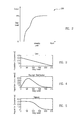
- FIGS. 3 through 5 illustrate graphs for exemplary transformations for the infrared camera or exemplary output histograms for the infrared camera data of FIG. 1 a and/or FIG. 1 b in accordance with embodiments of the present invention.
- FIG. 1 a shows a block diagram of a system 100 in accordance with an embodiment of the present invention.
- System 100 includes an infrared camera 102 , a controller 104 , one or more sensors 106 , display electronics 108 , and a display 110 .
- System 100 may be incorporated, for example, into a vehicle (e.g., an automobile or other type of land-based vehicle, an aircraft, or a spacecraft) or a non-mobile installation requiring infrared images to be stored and/or displayed. It should also be understood that system 100 may represent a portable infrared camera system (e.g., a handheld infrared camera).
- Controller 104 communicates with sensors 106 (e.g., by receiving sensor information from sensors 106 ) and with infrared camera 102 (e.g., by receiving data from infrared camera 102 and providing command, control, or other information to infrared camera 102 ).
- System 100 may also include display electronics 108 and display 110 , which are utilized by system 100 to display the data (e.g., infrared images) from infrared camera 102 .
- Display electronics 108 and display 110 may receive the data from infrared camera 102 via controller 104 (e.g., a processor or other type of logic or control device), as shown, or may receive the data directly from infrared camera 102 .
- controller 104 may be combined to include display electronics 108 , display 110 , infrared camera 102 , and/or one or more of sensors 106 .
- controller 104 may be incorporated into infrared camera 102 , with functions of controller 104 performed by circuitry (e.g., a microprocessor) within infrared camera 102 .
- system 100 may be incorporated into a vehicle (e.g., an automobile) to display infrared images via display 110 to one or more of the vehicle's occupants.
- Controller 104 may represent, for example, an electronic control unit (ECU) of the vehicle.
- Sensors 106 which may be integrated into the vehicle, provide information on current environmental conditions to controller 104 (e.g., via a controller area network (CAN) bus protocol).
- CAN controller area network
- sensors 106 may provide information regarding environmental conditions, such as outside temperature and/or temperature within infrared camera 102 , lighting conditions (e.g., day, night, dusk, and/or dawn), humidity level, specific weather conditions (e.g., sun, rain, and/or snow), and/or whether a tunnel, a covered parking garage, or other type of enclosure has been entered or exited.
- environmental conditions such as outside temperature and/or temperature within infrared camera 102 , lighting conditions (e.g., day, night, dusk, and/or dawn), humidity level, specific weather conditions (e.g., sun, rain, and/or snow), and/or whether a tunnel, a covered parking garage, or other type of enclosure has been entered or exited.
- one or more temperature sensors may be located within infrared camera 102 (e.g., within the housing), such as one near the front by the lens or by the infrared sensor and one near the back by the electronics, to monitor the internal temperature, which may affect the image and
- sensors 106 may also represent devices that relay information to controller 104 , with the information received by sensors 106 provided, for example, via wireless communication.
- sensors 106 within the vehicle may receive information from a satellite, through a local broadcast (e.g., radio frequency) transmission, through a mobile or cellular network, and/or through information beacons in an infrastructure (e.g., a transportation or highway information beacon infrastructure) or other wired or wireless techniques.
- a local broadcast e.g., radio frequency
- an infrastructure e.g., a transportation or highway information beacon infrastructure
- the information provided by sensors 106 may be evaluated and utilized by controller 104 to determine the proper operational parameters or settings for infrared camera 102 . For example, by using the information provided by sensors 106 (e.g., the vehicle's sensors) regarding external environmental conditions, the most appropriate transformation may be selected (e.g., by controller 104 or infrared camera 102 ) and applied to the data generated by infrared camera 102 .
- the transformation of the data may occur in infrared camera 102 , in display 110 , in an intermediate device (e.g., display electronics 108 ), or in some combination of these.
- parameters e.g., brightness, contrast, and/or gamma
- parameters e.g., brightness, contrast, and/or gamma
- controller 104 directly or via display electronics 108
- display electronics 108 may be adjusted (e.g., by controller 104 directly or via display electronics 108 ) based on information provided by sensors 106 regarding external environmental conditions.
- the optimization of the data (e.g., image or video image) from infrared camera 102 may require the generation and/or application of a specific transformation on the data.
- the transformation will transform the data from a higher to a lower resolution image (e.g., to a lower gray scale resolution).
- the transformation may translate the 14-bit data to 8-bit data, with the transformation applied based on the driving or environmental conditions (e.g., based on the information from the sensors 106 ).
- an improved image appearance may be obtained and stored and/or displayed as compared to the image appearance that would have resulted from a single, universal transformation applied for all environmental conditions or regardless of environmental conditions.
- Infrared camera 102 may store a number of selectable transformations that may be applied to the data generated by infrared camera 102 or controller 104 may generate and/or store the selectable transformations and apply the selected transformation to the data provided by infrared camera 102 .
- controller 104 may determine the appropriate transformation corresponding to the environmental conditions and command the transformation to be applied by infrared camera 102 (e.g., via a local interconnect network (LIN) protocol between infrared camera 102 and controller 104 ).
- LIN local interconnect network
- information regarding environmental conditions may be determined from the infrared camera data, with this information used to determine the appropriate transformation to apply to the infrared camera data.
- FIG. 1 b shows a block diagram of a system 150 in accordance with an embodiment of the present invention.
- System 150 is similar to system 100 ( FIG. 1 a ), but further illustrates that the data (e.g., image data) from infrared camera 102 may be analyzed (e.g., processed as shown in functional block 152 ) to determine environmental information, which may be used as discussed herein to select the appropriate transformation to apply to the infrared camera data.
- data e.g., image data
- functional block 152 e.g., processed as shown in functional block 152
- the image data may be processed (block 152 ) by analyzing the image data's histogram to determine environmental information (e.g., environmental conditions of the captured image).
- environmental information e.g., environmental conditions of the captured image
- the dynamic range may be determined by measuring the histogram width of the captured image from infrared camera 102 .
- a narrow width for the histogram may indicate, for example, fog or other type of low contrast environmental condition, while a wide width for the histogram may indicate a high contrast environmental condition (e.g., a clear, sunny day), as would be understood by one skilled in the art.
- a high contrast environmental condition e.g., a clear, sunny day
- FIG. 2 illustrates an example of an input-to-output transformation 200 that may be applied to data from infrared camera 102 of FIG. 1 a and/or FIG. 1 b in accordance with one or more embodiments of the present invention. Transformation 200 is shown plotted on a graph having an input axis of intensity level (e.g., analog or digital) and an output axis of gray level (e.g., digital output).
- intensity level e.g., analog or digital
- gray level e.g., digital output
- Transformation 200 may be applied, for example, to every pixel of the image data from infrared camera 102 .
- transformation 200 may represent one of a number of selectable transformations that may be applied to the infrared camera data based on environmental information obtained from the infrared camera data and/or from sensors 106 , as discussed herein and as would be understood by one skilled in the art. Consequently, after application of transformation 200 (or application of one of the other selectable transformations) to the infrared camera data, the infrared camera data will have a different histogram relative to the histogram of the infrared camera data prior to the application of transformation 200 (e.g., histogram conversion).
- a transformation may also be selected and applied based on environmental conditions, with the selected transformation indicating the type of display palette (e.g., a red palette for a dark environment or a black and white palette for a bright environment) to provide to display the transformed image data, as would be understood by one skilled in the art.
- the type of display palette e.g., a red palette for a dark environment or a black and white palette for a bright environment
- the histogram of the infrared camera data after application of the selected transformation (e.g., transformation 200 ) will depend on the histogram of the infrared camera data before application of the selected transformation and on the particular transformation selected (e.g., based on environmental conditions).
- a transformation 200 may be designed (e.g., transformation 200 or one of a number of transformations that may be selected) to obtain a desired output or resulting histogram after application of the transformation.
- the resulting histogram, after application of the transformation may be as shown in FIGS. 3-5 .
- FIGS. 3 through 5 illustrate graphs for exemplary transformations or output histograms (after application of the histogram conversion transformation) for the data generated by infrared camera 102 of FIG. 1 a and/or 1 b in accordance with an embodiment of the present invention.
- FIGS. 3-5 show only a few examples of the numerous transformations or alternatively output histograms that may be desired, as would be understood by one skilled in the art.
- each selectable transformation may be based on a composition of simpler transformations (e.g., with parameters based on the desired selectable transformation), which may be applied to generate the desired output histogram.
- spatial transformations may be performed before and/or after histogram conversion (e.g., application of the selected transformation).
- FIG. 3 illustrates an exemplary linear (ramp down) transformation or desired output histogram, which for example may be selected for daylight, dusk, or dawn environmental conditions.
- the linear transformation (or output histogram) may be represented by equation (1), where “k” equals the slope and “m” equals an offset.
- the value of “k” may be selected (e.g., a positive or a negative slope or no slope) for the linear transformation to provide a more optimal image appearance as a function of differing environmental conditions.
- y ( x ) kx+m (1)
- Additional logic or further transformation of the data may be performed based on information provided by sensors 106 .
- the particular transformation or output histogram e.g., Rayleigh
- the particular transformation or output histogram may be altered, distorted, or skewed as desired to change or further enhance the image appearance as a function of the environmental conditions.
- transformations and output histograms illustrated are exemplary and that a wide variety of transformations and histograms (e.g., piece-wise linear, Gaussian, or inverse Sigmoid or transformation permutations and variations) may be employed, as would be understood by one skilled in the art based on the techniques discussed herein.
- transformations and histograms e.g., piece-wise linear, Gaussian, or inverse Sigmoid or transformation permutations and variations
- various types of transformation techniques may be applied to the data generated by infrared camera 102 based on environmental information provided by sensors 106 and/or extracted from the image data from infrared camera 102 .
- display settings for display 110 may be adjusted based on environmental information provided by sensors 106 and/or extracted from the image data from infrared camera 102 .
- controller 104 may adjust one or more settings of display 110 based on environmental information provided by sensors 106 and/or extracted from the image data from infrared camera 102 .
- controller 104 may adjust a brightness setting, a contrast setting, a palette setting (e.g., red palette for dusk and at night, black and white palette for day), and/or a gamma setting of display 110 .
- an image optimization algorithm may be performed by controller 104 to control infrared camera 102 and/or display 110 to optimize the data and/or the image appearance based on environmental information.
- a different transformation may be selected or the transformation applied may have one or more of its parameters adjusted to account for the environmental condition.
- the display setting of display 110 may be adjusted to enhance the appearance of the images being displayed (e.g., palette selection, and/or brightness, contrast, and/or gamma incremented by one or two increments).
- interpolation may be performed to smoothly transition when switching from the application of one transformation to another as applied to the data generated by infrared camera 102 or when changing the display settings of display 110 .
- the display settings of display 110 may also be determined based on the selected transformation and/or the current environmental conditions. For example, the brightness and contrast settings of display 110 may be adjusted to ⁇ 3 and +3, respectively, from their nominal values when the linear transformation is applied. As another example, the brightness and contrast settings of display 110 may be adjusted to +3 and ⁇ 3, respectively, from their nominal values when the Rayleigh transformation or the Sigmoid transformation is applied. As another example, the display (e.g., palette or colors) may transition from a black and white display during brightly lit environments (e.g., during the day) to a red display during a dark environment (e.g., dusk, at night, or in a tunnel or darkened environment).
- a black and white display during brightly lit environments (e.g., during the day)
- a red display e.g., dusk, at night, or in a tunnel or darkened environment.
- an infrared camera that can apply logic selectively to transform the data generated by the infrared camera to account for changing environmental conditions.
- the infrared image quality may be improved for system operation over a wide range of scene environments (e.g., environmental conditions).
- an infrared camera system is disclosed that is incorporated into a vehicle.
- a processor on the vehicle e.g., the vehicle's electronic control unit or within the infrared camera
- switching logic i.e., decision logic
- the vehicle's sensors may provide information, such as for example day or night, dusk or dawn, whether the vehicle has entered a covered structure (e.g., a tunnel), and/or the specific weather condition (e.g., sun, rain, or snow). Additionally, the vehicle's sensors may provide information as to the type of environment, such as for example highway (or motorway), countryside (rural), city (urban), or residential area. For example, one or more of sensors 106 may represent a global positioning system (GPS) receiver or other type of location determining device, which may provide information as to the vehicle's position and the type of environment (e.g., exploiting data from geographical information systems (GIS)).
- GPS global positioning system
- the type of environment may also be determined by analyzing the image data from the infrared camera. Consequently, the selected transformation (and possibly other data processing functions for the infrared camera data) may be based at least partly on the type of environment during which the infrared camera data was obtained.
- the processor may select one from among a number of data transforms to apply to the data generated by the infrared camera (e.g., determines the mode for the infrared camera) based on the information from the vehicle's sensors (e.g., sensors 106 and/or by use of the infrared camera as a sensor).
- the infrared images being displayed may be dynamically optimized (i.e., in real time) by applying the appropriate transform to the data based on real-time sensor information (e.g., environmental conditions).
- real-time sensor information e.g., environmental conditions.
- the infrared camera may interpolate from one mode to the next (e.g., interpolation from one transform to the next) so that a gradual rather than a sudden change occurs in the images being displayed.
- display settings may be automatically adjusted (e.g., optionally with interpolation between the display setting changes) based on the environmental conditions or on the selected transformation to further enhance the images being displayed.
- high-pass filtering may also be selected based on the width of the histogram from the infrared camera (e.g., prior to the application of the transformation) in accordance with an embodiment of the present invention.
- the degree and other parameters of the high-pass filtering may be based on the input histogram width.
- various parameters of the high-pass filtering such as kernel size, cut-on frequency, and/or filter strength (e.g., what fraction of the low-frequency content is added back), may be varied as a function of scene/environmental conditions.
- high-pass filtering may be based on vehicle movement (e.g., speed and/or rate of change of direction) as determined by sensors 106 (e.g., GPS information as discussed herein).
Landscapes
- Engineering & Computer Science (AREA)
- Physics & Mathematics (AREA)
- General Physics & Mathematics (AREA)
- Theoretical Computer Science (AREA)
- Multimedia (AREA)
- Signal Processing (AREA)
- Studio Devices (AREA)
- Closed-Circuit Television Systems (AREA)
Abstract
Description
y(x)=kx+m (1)
Claims (25)
Priority Applications (1)
| Application Number | Priority Date | Filing Date | Title |
|---|---|---|---|
| US12/035,594 US8077995B1 (en) | 2005-02-23 | 2008-02-22 | Infrared camera systems and methods using environmental information |
Applications Claiming Priority (2)
| Application Number | Priority Date | Filing Date | Title |
|---|---|---|---|
| US11/064,987 US7340162B2 (en) | 2005-02-23 | 2005-02-23 | Infrared camera systems and methods |
| US12/035,594 US8077995B1 (en) | 2005-02-23 | 2008-02-22 | Infrared camera systems and methods using environmental information |
Related Parent Applications (1)
| Application Number | Title | Priority Date | Filing Date |
|---|---|---|---|
| US11/064,987 Continuation-In-Part US7340162B2 (en) | 2005-02-23 | 2005-02-23 | Infrared camera systems and methods |
Publications (1)
| Publication Number | Publication Date |
|---|---|
| US8077995B1 true US8077995B1 (en) | 2011-12-13 |
Family
ID=45092740
Family Applications (1)
| Application Number | Title | Priority Date | Filing Date |
|---|---|---|---|
| US12/035,594 Expired - Fee Related US8077995B1 (en) | 2005-02-23 | 2008-02-22 | Infrared camera systems and methods using environmental information |
Country Status (1)
| Country | Link |
|---|---|
| US (1) | US8077995B1 (en) |
Cited By (12)
| Publication number | Priority date | Publication date | Assignee | Title |
|---|---|---|---|---|
| US20090295801A1 (en) * | 2008-05-28 | 2009-12-03 | Dominik Fritz | Method for visualizing tubular anatomical structures, in particular vessel structures, in medical 3D image records |
| US20110249119A1 (en) * | 2009-01-30 | 2011-10-13 | David Forslund | Safety System for a Motor Vehicle |
| US20120242806A1 (en) * | 2011-03-23 | 2012-09-27 | Tk Holdings Inc. | Dynamic stereo camera calibration system and method |
| US20130063602A1 (en) * | 2011-09-12 | 2013-03-14 | Bruce Scapier | System and method for remote monitoring of equipment moisture exposure |
| US20140022380A1 (en) * | 2012-07-19 | 2014-01-23 | Bell Helicopter Textron Inc. | Nondestructive Inspection Techniques for Rotorcraft Composites |
| US20170069093A1 (en) * | 2015-09-03 | 2017-03-09 | Robert Bosch Gmbh | Method for detecting objects on a parking area |
| BE1024436B1 (en) * | 2016-06-10 | 2018-02-27 | Sensors Unlimited Inc. | IMAGE ENHANCEMENT |
| US20180285680A1 (en) * | 2017-04-03 | 2018-10-04 | Hanwha Techwin Co., Ltd. | Method and apparatus for detecting fog from image |
| KR20210055584A (en) * | 2019-11-07 | 2021-05-17 | 엑시스 에이비 | Method for displaying a video stream of a scene |
| US11113540B2 (en) * | 2019-05-20 | 2021-09-07 | Panasonic I-Pro Sensing Solutions Co., Ltd. | Vehicle monitoring system and vehicle monitoring method |
| US11220355B2 (en) * | 2012-07-19 | 2022-01-11 | Textron Innovations Inc. | Nondestructive inspection techniques for rotorcraft composites |
| US11509874B2 (en) * | 2018-02-16 | 2022-11-22 | Nec Platforms, Ltd. | Video projector and video display method |
Citations (18)
| Publication number | Priority date | Publication date | Assignee | Title |
|---|---|---|---|---|
| US5083208A (en) | 1988-12-26 | 1992-01-21 | Ricoh Company, Ltd. | Electronic zoom apparatus |
| US5341142A (en) * | 1987-07-24 | 1994-08-23 | Northrop Grumman Corporation | Target acquisition and tracking system |
| US5799106A (en) | 1991-07-09 | 1998-08-25 | The United States Of America As Represented By The Secretary Of The Air Force | Noise immune automated contrast control for infrared cameras |
| US6026340A (en) * | 1998-09-30 | 2000-02-15 | The Robert Bosch Corporation | Automotive occupant sensor system and method of operation by sensor fusion |
| JP2001154646A (en) | 1999-11-26 | 2001-06-08 | Fujitsu Ltd | Infrared picture display device |
| US6272411B1 (en) * | 1994-04-12 | 2001-08-07 | Robert Bosch Corporation | Method of operating a vehicle occupancy state sensor system |
| JP2003164414A (en) | 2001-11-29 | 2003-06-10 | Fuji Photo Film Co Ltd | Method and device for displaying fluoroscopic image |
| EP1333660A2 (en) | 2002-01-31 | 2003-08-06 | Eastman Kodak Company | Adjusting the color, brightness, and tone scale of rendered digital images |
| US20030146383A1 (en) | 2000-03-17 | 2003-08-07 | Knauth Jonathan P. | Method and apparatus for correction of microbolometer output |
| JP2004123061A (en) | 2002-10-07 | 2004-04-22 | Toyota Motor Corp | Photographing system |
| US6768944B2 (en) * | 2002-04-09 | 2004-07-27 | Intelligent Technologies International, Inc. | Method and system for controlling a vehicle |
| WO2004070449A1 (en) | 2003-02-06 | 2004-08-19 | Bayerische Motoren Werke Aktiengesellschaft | Method and device for visualizing a motor vehicle environment with environment-dependent fusion of an infrared image and a visual image |
| US20040165749A1 (en) | 2003-01-24 | 2004-08-26 | Daimlerchrysler Ag | Device and method for vision enhancement and for determining the weather situation |
| US6850642B1 (en) | 2000-01-31 | 2005-02-01 | Micron Technology, Inc. | Dynamic histogram equalization for high dynamic range images |
| US7027619B2 (en) * | 2001-09-13 | 2006-04-11 | Honeywell International Inc. | Near-infrared method and system for use in face detection |
| US7265661B2 (en) | 2003-07-22 | 2007-09-04 | Nissan Motor Co., Ltd. | Display system for vehicle and method of controlling the same |
| US7527288B2 (en) * | 1995-06-07 | 2009-05-05 | Automotive Technologies International, Inc. | Vehicle with crash sensor coupled to data bus |
| US7762582B2 (en) * | 1995-06-07 | 2010-07-27 | Automotive Technologies International, Inc. | Vehicle component control based on occupant morphology |
-
2008
- 2008-02-22 US US12/035,594 patent/US8077995B1/en not_active Expired - Fee Related
Patent Citations (18)
| Publication number | Priority date | Publication date | Assignee | Title |
|---|---|---|---|---|
| US5341142A (en) * | 1987-07-24 | 1994-08-23 | Northrop Grumman Corporation | Target acquisition and tracking system |
| US5083208A (en) | 1988-12-26 | 1992-01-21 | Ricoh Company, Ltd. | Electronic zoom apparatus |
| US5799106A (en) | 1991-07-09 | 1998-08-25 | The United States Of America As Represented By The Secretary Of The Air Force | Noise immune automated contrast control for infrared cameras |
| US6272411B1 (en) * | 1994-04-12 | 2001-08-07 | Robert Bosch Corporation | Method of operating a vehicle occupancy state sensor system |
| US7762582B2 (en) * | 1995-06-07 | 2010-07-27 | Automotive Technologies International, Inc. | Vehicle component control based on occupant morphology |
| US7527288B2 (en) * | 1995-06-07 | 2009-05-05 | Automotive Technologies International, Inc. | Vehicle with crash sensor coupled to data bus |
| US6026340A (en) * | 1998-09-30 | 2000-02-15 | The Robert Bosch Corporation | Automotive occupant sensor system and method of operation by sensor fusion |
| JP2001154646A (en) | 1999-11-26 | 2001-06-08 | Fujitsu Ltd | Infrared picture display device |
| US6850642B1 (en) | 2000-01-31 | 2005-02-01 | Micron Technology, Inc. | Dynamic histogram equalization for high dynamic range images |
| US20030146383A1 (en) | 2000-03-17 | 2003-08-07 | Knauth Jonathan P. | Method and apparatus for correction of microbolometer output |
| US7027619B2 (en) * | 2001-09-13 | 2006-04-11 | Honeywell International Inc. | Near-infrared method and system for use in face detection |
| JP2003164414A (en) | 2001-11-29 | 2003-06-10 | Fuji Photo Film Co Ltd | Method and device for displaying fluoroscopic image |
| EP1333660A2 (en) | 2002-01-31 | 2003-08-06 | Eastman Kodak Company | Adjusting the color, brightness, and tone scale of rendered digital images |
| US6768944B2 (en) * | 2002-04-09 | 2004-07-27 | Intelligent Technologies International, Inc. | Method and system for controlling a vehicle |
| JP2004123061A (en) | 2002-10-07 | 2004-04-22 | Toyota Motor Corp | Photographing system |
| US20040165749A1 (en) | 2003-01-24 | 2004-08-26 | Daimlerchrysler Ag | Device and method for vision enhancement and for determining the weather situation |
| WO2004070449A1 (en) | 2003-02-06 | 2004-08-19 | Bayerische Motoren Werke Aktiengesellschaft | Method and device for visualizing a motor vehicle environment with environment-dependent fusion of an infrared image and a visual image |
| US7265661B2 (en) | 2003-07-22 | 2007-09-04 | Nissan Motor Co., Ltd. | Display system for vehicle and method of controlling the same |
Cited By (22)
| Publication number | Priority date | Publication date | Assignee | Title |
|---|---|---|---|---|
| US20090295801A1 (en) * | 2008-05-28 | 2009-12-03 | Dominik Fritz | Method for visualizing tubular anatomical structures, in particular vessel structures, in medical 3D image records |
| US20110249119A1 (en) * | 2009-01-30 | 2011-10-13 | David Forslund | Safety System for a Motor Vehicle |
| US9158978B2 (en) * | 2009-01-30 | 2015-10-13 | Autoliv Development Ab | Vehicle environment classifying safety system for a motor vehicle |
| US20120242806A1 (en) * | 2011-03-23 | 2012-09-27 | Tk Holdings Inc. | Dynamic stereo camera calibration system and method |
| US20130063602A1 (en) * | 2011-09-12 | 2013-03-14 | Bruce Scapier | System and method for remote monitoring of equipment moisture exposure |
| US20140022380A1 (en) * | 2012-07-19 | 2014-01-23 | Bell Helicopter Textron Inc. | Nondestructive Inspection Techniques for Rotorcraft Composites |
| US11220355B2 (en) * | 2012-07-19 | 2022-01-11 | Textron Innovations Inc. | Nondestructive inspection techniques for rotorcraft composites |
| CN106504561B (en) * | 2015-09-03 | 2021-07-27 | 罗伯特·博世有限公司 | Method for identifying objects in a parking area |
| CN106504561A (en) * | 2015-09-03 | 2017-03-15 | 罗伯特·博世有限公司 | Method for recognizing the object on parking area |
| US10007268B2 (en) * | 2015-09-03 | 2018-06-26 | Robert Bosch Gmbh | Method for detecting objects on a parking area |
| US20170069093A1 (en) * | 2015-09-03 | 2017-03-09 | Robert Bosch Gmbh | Method for detecting objects on a parking area |
| US10007974B2 (en) | 2016-06-10 | 2018-06-26 | Sensors Unlimited, Inc. | Enhancing images |
| BE1024436B1 (en) * | 2016-06-10 | 2018-02-27 | Sensors Unlimited Inc. | IMAGE ENHANCEMENT |
| US10346961B2 (en) | 2016-06-10 | 2019-07-09 | Sensors Unlimited, Inc. | Enhancing images |
| US20180285680A1 (en) * | 2017-04-03 | 2018-10-04 | Hanwha Techwin Co., Ltd. | Method and apparatus for detecting fog from image |
| US10853685B2 (en) * | 2017-04-03 | 2020-12-01 | Hanwha Techwin Co., Ltd. | Method and apparatus for detecting fog from image |
| US11509874B2 (en) * | 2018-02-16 | 2022-11-22 | Nec Platforms, Ltd. | Video projector and video display method |
| US11113540B2 (en) * | 2019-05-20 | 2021-09-07 | Panasonic I-Pro Sensing Solutions Co., Ltd. | Vehicle monitoring system and vehicle monitoring method |
| US11765322B2 (en) | 2019-05-20 | 2023-09-19 | i-PRO Co., Ltd. | Vehicle monitoring system and vehicle monitoring method |
| KR20210055584A (en) * | 2019-11-07 | 2021-05-17 | 엑시스 에이비 | Method for displaying a video stream of a scene |
| US11546558B2 (en) * | 2019-11-07 | 2023-01-03 | Axis Ab | Method for displaying a video stream of a scene |
| TWI832011B (en) * | 2019-11-07 | 2024-02-11 | 瑞典商安訊士有限公司 | Method for displaying a video stream of a scene |
Similar Documents
| Publication | Publication Date | Title |
|---|---|---|
| US8077995B1 (en) | Infrared camera systems and methods using environmental information | |
| US7340162B2 (en) | Infrared camera systems and methods | |
| US8515196B1 (en) | Systems and methods for processing infrared images | |
| JP4985394B2 (en) | Image processing apparatus and method, program, and recording medium | |
| JP4543147B2 (en) | Panorama vision system and method | |
| US20060017807A1 (en) | Panoramic vision system and method | |
| JP4491453B2 (en) | Method and apparatus for visualizing the periphery of a vehicle by fusing infrared and visual images depending on the periphery | |
| US9215384B2 (en) | Method of processing an infrared image, infrared image capturing system and computer readable medium | |
| CN109923580B (en) | Dynamic range compression for thermal video | |
| US20150332441A1 (en) | Selective image correction for infrared imaging devices | |
| JP3782322B2 (en) | In-vehicle image processing camera device | |
| CN211825673U (en) | Image forming apparatus with a plurality of image forming units | |
| WO2014100783A1 (en) | Time spaced infrared image enhancement | |
| KR20010033768A (en) | Vehicle vision system | |
| WO2005081516A1 (en) | Image data conversion device and camera device | |
| US9875556B2 (en) | Edge guided interpolation and sharpening | |
| US20200304752A1 (en) | Method and apparatus for enhanced video display | |
| JP5865726B2 (en) | Video display device | |
| US10525902B2 (en) | Convertible roof opening detection for mirror camera | |
| WO2010002379A1 (en) | Digital camera control system | |
| CN112365626A (en) | Vehicle-mounted camera picture processing method | |
| EP2894846B1 (en) | Imaging device, imaging method, image processing device, and carrier means | |
| JP4973565B2 (en) | Road condition grasping system and road condition grasping method | |
| JP6593581B2 (en) | Image quality adjusting device and camera unit | |
| WO2024167905A1 (en) | Image local contrast enhancement systems and methods |
Legal Events
| Date | Code | Title | Description |
|---|---|---|---|
| AS | Assignment |
Owner name: FLIR SYSTEMS, INC., 27700A SW AVENUE, WILSONVILLE, Free format text: ASSIGNMENT OF ASSIGNORS INTEREST;ASSIGNORS:TERRE, BILL;KOSTRZEWA, JOSEPH;KALLHAMMER, JAN-ERIK;AND OTHERS;SIGNING DATES FROM 20080227 TO 20080416;REEL/FRAME:020840/0566 |
|
| AS | Assignment |
Owner name: BANK OF AMERICA, N.A., AS ADMINISTRATIVE AGENT, WA Free format text: NOTICE OF GRANT OF SECURITY INTEREST IN PATENTS;ASSIGNOR:INDIGO SYSTEMS, INC.;REEL/FRAME:021554/0180 Effective date: 20061006 |
|
| ZAAA | Notice of allowance and fees due |
Free format text: ORIGINAL CODE: NOA |
|
| ZAAB | Notice of allowance mailed |
Free format text: ORIGINAL CODE: MN/=. |
|
| STCF | Information on status: patent grant |
Free format text: PATENTED CASE |
|
| FPAY | Fee payment |
Year of fee payment: 4 |
|
| MAFP | Maintenance fee payment |
Free format text: PAYMENT OF MAINTENANCE FEE, 8TH YEAR, LARGE ENTITY (ORIGINAL EVENT CODE: M1552); ENTITY STATUS OF PATENT OWNER: LARGE ENTITY Year of fee payment: 8 |
|
| AS | Assignment |
Owner name: VEONEER SWEDEN AB, SWEDEN Free format text: ASSIGNMENT OF ASSIGNORS INTEREST;ASSIGNOR:AUTOLIV DEVELOPMENT AB;REEL/FRAME:053845/0928 Effective date: 20180401 |
|
| AS | Assignment |
Owner name: TELEDYNE FLIR, LLC, CALIFORNIA Free format text: MERGER AND CHANGE OF NAME;ASSIGNORS:FLIR SYSTEMS, INC.;FIREWORK MERGER SUB II, LLC;REEL/FRAME:058832/0915 Effective date: 20210514 |
|
| FEPP | Fee payment procedure |
Free format text: MAINTENANCE FEE REMINDER MAILED (ORIGINAL EVENT CODE: REM.); ENTITY STATUS OF PATENT OWNER: LARGE ENTITY |
|
| LAPS | Lapse for failure to pay maintenance fees |
Free format text: PATENT EXPIRED FOR FAILURE TO PAY MAINTENANCE FEES (ORIGINAL EVENT CODE: EXP.); ENTITY STATUS OF PATENT OWNER: LARGE ENTITY |
|
| STCH | Information on status: patent discontinuation |
Free format text: PATENT EXPIRED DUE TO NONPAYMENT OF MAINTENANCE FEES UNDER 37 CFR 1.362 |
|
| FP | Lapsed due to failure to pay maintenance fee |
Effective date: 20231213 |
|
| AS | Assignment |
Owner name: MAGNA ELECTRONICS SWEDEN AB, SWEDEN Free format text: CHANGE OF NAME;ASSIGNOR:VEONEER SWEDEN AB;REEL/FRAME:066816/0846 Effective date: 20231107 |