US8075420B2 - Hardened golf club head - Google Patents
Hardened golf club head Download PDFInfo
- Publication number
- US8075420B2 US8075420B2 US12/490,666 US49066609A US8075420B2 US 8075420 B2 US8075420 B2 US 8075420B2 US 49066609 A US49066609 A US 49066609A US 8075420 B2 US8075420 B2 US 8075420B2
- Authority
- US
- United States
- Prior art keywords
- golf club
- striking face
- club head
- face portion
- hardness
- Prior art date
- Legal status (The legal status is an assumption and is not a legal conclusion. Google has not performed a legal analysis and makes no representation as to the accuracy of the status listed.)
- Active, expires
Links
Images


Classifications
-
- A—HUMAN NECESSITIES
- A63—SPORTS; GAMES; AMUSEMENTS
- A63B—APPARATUS FOR PHYSICAL TRAINING, GYMNASTICS, SWIMMING, CLIMBING, OR FENCING; BALL GAMES; TRAINING EQUIPMENT
- A63B53/00—Golf clubs
- A63B53/04—Heads
- A63B53/047—Heads iron-type
-
- A—HUMAN NECESSITIES
- A63—SPORTS; GAMES; AMUSEMENTS
- A63B—APPARATUS FOR PHYSICAL TRAINING, GYMNASTICS, SWIMMING, CLIMBING, OR FENCING; BALL GAMES; TRAINING EQUIPMENT
- A63B53/00—Golf clubs
- A63B53/04—Heads
- A63B53/0408—Heads characterised by specific dimensions, e.g. thickness
-
- A—HUMAN NECESSITIES
- A63—SPORTS; GAMES; AMUSEMENTS
- A63B—APPARATUS FOR PHYSICAL TRAINING, GYMNASTICS, SWIMMING, CLIMBING, OR FENCING; BALL GAMES; TRAINING EQUIPMENT
- A63B53/00—Golf clubs
- A63B53/04—Heads
- A63B53/0458—Heads with non-uniform thickness of the impact face plate
-
- A—HUMAN NECESSITIES
- A63—SPORTS; GAMES; AMUSEMENTS
- A63B—APPARATUS FOR PHYSICAL TRAINING, GYMNASTICS, SWIMMING, CLIMBING, OR FENCING; BALL GAMES; TRAINING EQUIPMENT
- A63B60/00—Details or accessories of golf clubs, bats, rackets or the like
-
- A—HUMAN NECESSITIES
- A63—SPORTS; GAMES; AMUSEMENTS
- A63B—APPARATUS FOR PHYSICAL TRAINING, GYMNASTICS, SWIMMING, CLIMBING, OR FENCING; BALL GAMES; TRAINING EQUIPMENT
- A63B2209/00—Characteristics of used materials
-
- A—HUMAN NECESSITIES
- A63—SPORTS; GAMES; AMUSEMENTS
- A63B—APPARATUS FOR PHYSICAL TRAINING, GYMNASTICS, SWIMMING, CLIMBING, OR FENCING; BALL GAMES; TRAINING EQUIPMENT
- A63B53/00—Golf clubs
- A63B53/04—Heads
- A63B53/0416—Heads having an impact surface provided by a face insert
- A63B53/042—Heads having an impact surface provided by a face insert the face insert consisting of a material different from that of the head
-
- A—HUMAN NECESSITIES
- A63—SPORTS; GAMES; AMUSEMENTS
- A63B—APPARATUS FOR PHYSICAL TRAINING, GYMNASTICS, SWIMMING, CLIMBING, OR FENCING; BALL GAMES; TRAINING EQUIPMENT
- A63B53/00—Golf clubs
- A63B53/04—Heads
- A63B53/0445—Details of grooves or the like on the impact surface
-
- A—HUMAN NECESSITIES
- A63—SPORTS; GAMES; AMUSEMENTS
- A63B—APPARATUS FOR PHYSICAL TRAINING, GYMNASTICS, SWIMMING, CLIMBING, OR FENCING; BALL GAMES; TRAINING EQUIPMENT
- A63B53/00—Golf clubs
- A63B53/04—Heads
- A63B53/0466—Heads wood-type
-
- A—HUMAN NECESSITIES
- A63—SPORTS; GAMES; AMUSEMENTS
- A63B—APPARATUS FOR PHYSICAL TRAINING, GYMNASTICS, SWIMMING, CLIMBING, OR FENCING; BALL GAMES; TRAINING EQUIPMENT
- A63B53/00—Golf clubs
- A63B53/04—Heads
- A63B53/0487—Heads for putters
Definitions
- the present invention relates to a hardened golf club head. More particularly, the present invention relates to a golf club head with a surface transformation that increases the hardness of the striking surface of the golf club head. Even more particularly, the present invention relates to a golf club head wherein the striking surface layer has been transformed into a martensitic crystalline structure to promote enhanced performance and durability.
- Wedge type golf club heads are a particular type of golf club that generally has a high loft angle. These higher lofted wedges tend to be precision instruments that allow a golfer to dial in short range golf shots with improved trajectory, improved accuracy, and improved control. This increased loft angle in wedges generally yield a golf shot with a higher trajectory because the impact surface on the golf ball is not perpendicular to the trajectory of the club head; rather the golf ball interacts with the wedge at an inclination closely resembling the actual loft angle of the wedge itself.
- This inclination generally causes the golf ball to move up along the inclination of the wedge when struck by the wedge type golf club head, creating a backward rotation of the golf ball as it leaves the wedge club face.
- This backwards rotation of the golf ball may generally be known as “backspin” within the golf industry; and this backspin is desirable in helping improve trajectory, accuracy, and control of a golf shot using a wedge type golf club head.
- Backspin helps improve trajectory, accuracy, and control of a golf shot by giving the golf ball a gyroscopic effect, which stabilizes trajectory, hence increasing accuracy. Moreover, backspin also serves to increase control of a golf shot as backspin minimizes the roll of a golf ball after landing, allowing a more predictability.
- wedge type golf club heads In order to achieve this higher coefficient of friction, wedge type golf club heads generally have horizontal grooves at the striking surface to catch the golf ball as it leaves the face of the club. It is well known in the art that the shape, depth, width, and geometry of the grooves on the striking surface of a wedge have a direct correlation with the amount of backspin on a golf ball.
- the grooves are getting sharper and more aggressive and creating more backspin.
- these sharper and more aggressive grooves are more prone to wear over time. This wear is often caused by erosion that results from repeated impact between a golf ball and the wedge type golf club head.
- this erosion process can be intensified when various other harsh abrasives such as soil and sand that could get caught between the wedge type golf club and a golf ball.
- the wear and tear on the horizontal grooves of a wedge type golf club head may generally decrease the amount of backspin on a wedge type golf club head over time, leading to a decrease in its performance characteristics.
- U.S. Pat. No. 4,768,787 to Shira titled Golf Club Including High Friction Striking Face ('787 Patent), although more particularly directed towards an iron type golf club head, provides a more detailed example of a golf club with an improved striking surface wherein the striking surface has hard particles embedded therein with portions of the particles protruding above the surface so as to provide greater frictional grip between the golf ball striking surface and the golf ball. More specifically, the '787 Patent discloses a club wherein the hard particles project or protrude slightly above the ball striking surface of the “iron” head and create friction between the club and the golf ball. Over an extended period of service, the matrix material will wear more rapidly than the hard particles, and the hard particles will continue to perform their friction creating function.
- most of the modern wedges may generally be comprised of a carbon steel material that may have certain materials properties that lends itself well to heat transformation surface transformation. All of the above mentioned approaches to extending the performance characteristics of a wedge type golf club head do not utilize or take advantage of the inherent physical properties of the material from which the wedge type golf club head is made from. Martensitic crystalline layer may generally be achieved by heat treating the surface of a wedge that is comprised of carbon steel and rapidly quenching the wedge in a fluid to change the material properties of the heat treated surface.
- a golf club head comprising of a body portion and a hosel extending from the body portion.
- the relationship of the body portion and the hosel help define a loft angle of the golf club head to be greater than about 45 degrees.
- the body portion of the golf club head may be further comprised of a striking face portion and a rear portion wherein the striking face portion has a thickness of less than about 2.0 mm and the striking face portion is comprised of a material having a martensitic crystalline structure.
- a method hardening a striking face portion of a golf club head comprising of heating the striking face portion of the golf club head to a target temperature and target duration. After the heating the striking face portion is rapidly quenched in a coolant to create a martensitic striking face portion.
- the golf club head may generally have a loft angle that is greater than about 45 degrees and the striking face portion may transform into a material having a martensitic crystalline structure.
- a golf club head comprising of a body portion and a hosel extending from the body portion.
- the relationship of the body portion and the hosel help define a loft angle of the golf club head to be greater than about 45 degrees.
- the body portion of the golf club head may be further comprised of a striking face portion and a rear portion where the ratio of hardness of the striking face portion is greater than about 1.3 of the hardness of the rear portion defining a striking face hardness ratio.
- FIG. 1 shows a perspective view of a wedge type golf club head in accordance with an exemplary embodiment of the present invention
- FIG. 2 shows a side view of a wedge type golf club head in accordance with an exemplary embodiment of the present invention
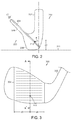
- FIG. 3 shows a frontal view of a wedge type golf club head in accordance with an exemplary embodiment of the present invention
- FIG. 4 a shows a cross-sectional view of a wedge type golf club head in accordance with an exemplary embodiment of the present invention taken along cross-sectional line A-A′ as shown in FIG. 3 ;
- FIG. 4 b shows a cross-sectional view of a wedge type golf club head in accordance with an exemplary embodiment of the present invention taken along cross-sectional line A-A′ as shown in FIG. 3 ;
- FIG. 5 shows a graphical representation of the hardness profile of the wedge type golf club head
- FIG. 6 shows a side view of a wedge type golf club head in accordance with an alternative embodiment of the present invention
- FIG. 7 shows a frontal view of a wedge type golf club head in accordance with an exemplary embodiment of the present invention showing the hardness distribution profile
- FIG. 8 shows a frontal view of a wedge type golf club head in accordance with an alternative embodiment of the present invention showing the hardness distribution profile
- FIG. 9 shows a block diagram of a method of creating a wedge type golf club head having a hardened striking face portion.
- the present invention generally provides a golf club head with a surface treatment that transformations and hardens of the striking surface portion of a golf club head. More specifically, the present invention relates to a wedge type golf club head made out of carbon steel that has a martensitic crystalline structure on the surface layer of the striking surface portion that enhances the strength of the wedge type golf club head as well as increase durability.
- the current invention is unlike the prior art golf clubs that utilizes additional additives or surface treatments that do not take advantage of the inherent performance characteristics within a wedge to maximize its performance.
- FIG. 1 shows a perspective view of an exemplary embodiment of the present invention wherein the golf club head 100 is shown having a hosel 102 capable of connecting the golf club head 100 to a shaft (not shown).
- Golf club head 100 may contain a body 103 that further comprises of a striking face portion 104 and a rear portion 106 that is separated by a sole 108 at the bottom of the golf club head 100 .
- FIG. 1 may also show an impact point 110 located on the striking face portion of the golf club head 100 reflecting the general impact point between a golf club head 100 and a golf ball (not shown).
- a wedge type golf club head 100 is used for illustration purposes here because a wedge type golf club head 100 may generally need to retain the shape of their sharp grooves in order to perform at creating spin.
- the present invention may be applicable to other types of clubs such as iron type golf club heads or even driver type golf club heads just as well as wedge type golf club head 100 without departing form the scope and content of the present invention.
- Golf club head 100 may generally be made out of steel due to its inherent optimal high ductility, high strength, and soft feel characteristics.
- numerous other types of materials such as cast irons, gray irons, or even non-ferrous alloys may be used so long as it is capable of forming a golf club head 100 that can strike a golf ball all without departing from the scope and content of the present invention.
- golf club head 100 may be generally be of a carbon steel type material such as low carbon steel, medium carbon steel, or high carbon steel.
- golf club head 100 may generally be a medium carbon steel type material such as 8600 series steel, 9200 series steel, 6100 series steel, 5100 series steel, 4800 series steel, or any other type of medium carbon steel without departing from the scope and content of the present invention.
- golf club head 100 may most preferably be made out of cast 8620 steel due to the fact that it contains an optimal balance of all the desirable characteristics such as high ductility, high strength, soft feel, and its ability to transform into a martensitic crystalline metal.
- Hosel 102 may generally be comprised of the same material as the remainder of the golf type club head 100 . Having the hosel 102 be comprised out of a ductile material such as cast 8620 steel may be advantageous in allowing the hosel 102 to be bent to a different position allowing for loft and lie adjustment of the wedge; however numerous other materials may also be used to form the hosel 102 of the golf club head 100 even if it is not the same material as the remainder of the golf club head 100 without departing from the scope and content of the present invention. Golf club head 100 , including hosel 102 may generally be comprised of a unitary material such as the medium carbon steel of the 8620 class in order to maintain consistency. However, hosel 102 of the golf club head 100 may be comprised of a completely different material to differentiate the look and feel of the golf club head 100 all without departing from the scope and content of the present invention.
- a ductile material such as cast 8620 steel
- Body 103 Connected distally to the hosel 102 at the bottom of the golf club head 100 is the body 103 portion.
- Body 103 may generally also be made out of the same ductile material such as cast 8620 steel mentioned above.
- the ductility of 8620 steel despite being advantageous in being easily bendable in the hosel 102 , also provide a soft feel to the golf club head 100 upon impact.
- body 103 of the golf club head 100 may also be of a different material such as stainless steel, cast irons, gray irons, or even non-ferrous alloys so long as it is capable of forming a golf club head 100 .
- Body 103 may generally be further identified as containing a striking face portion 104 and a rear portion 106 .
- Striking face portion 104 may generally include a frontal layer of the golf club head 100 , including the striking surface of the golf club head 100 , upon which a ball impacts a golf ball.
- Striking face portion 104 as shown in the current exemplary embodiment, may more specifically be comprised of a martensitic layer that contains a martensitic crystalline structure with an increased hardness when compared to the hardness of the rear portion 106 of the golf club head 100 .
- Having a martensitic layered striking face portion 104 may generally increase the performance characteristics of a golf club head 100 by maintaining the shape of the grooves for a longer period of time and preserving spin characteristics while preserving the soft feel around the remainder of the golf club head 100 .
- Martensitic striking face portion 104 may generally be formed by heating the striking face portion 104 of the golf club head 100 utilizing a flame and then immediately quenching the striking face portion 104 of the golf club head 100 into a coolant.
- This methodology of creating a martensitic striking face portion 104 may result in a striking face portion 104 having an increased hardness while preserving the ductility of the remainder of the golf club head 100 .
- Having ductility in the hosel 102 may generally allow more bending of the hosel 102 , while having ductility within the rear portion 106 of the golf club head 100 increases softness and feel for the golf club head 100 .
- the heating process described above should generally be performed utilizing a centralized flame source located at the impact point 110 of the striking face portion 104 of the golf club head 100 .
- Utilizing a centralized flame source located at the impact point 110 will allow the martensitic transformation of the striking face portion 104 of the golf club head 100 without affecting the hardness of the remainder of the golf club head 100 such as the hosel 102 and the rear portion 106 .
- centralizing and focusing the flame source at the impact point 110 may allow a hardness gradient within the striking face portion 104 of the golf club head 100 , yielding the hardest point at the impact point 110 , and a gradual decrease of hardness as the distance gets further apart from the impact point 110 . (see FIGS.
- the flame could be centralized at any other location within the striking face portion 104 , or even evenly distributed across the entire striking face portion 104 so long as it creates a martensitic layer all without departing from the scope and content of the present invention.
- the striking face portion 104 may be heated utilizing an induction method wherein the striking face portion 104 may be heated by electromagnetic induction where the eddy currents are generated within the metal and resistance leads to joule heating of the striking face portion 104 .
- the striking face portion 104 of the golf club head 100 may be connected to an AC power supply that provides electricity with a low voltage along with a high current and high frequency wherein the striking face portion 104 may be placed inside an air coil driver by the power supply. Once the striking face portion 104 of the golf club head 100 reaches the desired temperature, the striking face portion 104 may be quenched in a liquid coolant such as water.
- This cooling process may be either concentrated at the striking face portion 104 or it may occur through the entire golf club head 100 all without departing from the scope and content of the present invention.
- the striking face portion 104 may yield a hardened martensitic striking face portion 104 with more uniformity and more controlled results.
- the golf club head 100 In order to achieve a martensitic striking face portion 104 , the golf club head 100 needs to be heated to a desired temperature.
- the desired temperature may vary depending on the speed of cooling but may generally be greater than about 600 degrees Celsius, more preferably greater than about degrees 700 Celsius, and most preferably greater than about 800 degrees Celsius.
- the cooling rate of the golf club head 100 may also be another important factor that needs to be controlled in order to generate a martensitic striking face portion 104 .
- the cooling rate needs to happen rapidly at a rate of greater than about 1,000 degrees Celsius per second, more preferably greater than about 2,500 degrees Celsius per second, and most preferably greater than 5,000 degrees Celsius per second.
- heating and cooling methods may generally be applicable towards the striking face portion 104 of the wedge type golf club head 100 .
- Other methods such as tempering may be used to relax or soften the rear portion 106 while maintaining the hardness of the striking face portion without departing from the scope and content of the present invention.
- FIG. 2 shows a side view of an exemplary embodiment of the present invention capable of showing the height and location of the impact point 110 in FIG. 1 in more detail being depicted as impact point 210 .
- Impact point 210 may generally be located on the striking face portion 204 of the golf club head 200 ; reflective of the common location of impact between the golf club head 200 and a golf ball (not shown).
- Impact point 210 may generally be at a distance d 2 away from the ground 211 along the vertical direction.
- This distance d 2 may be from about 10 mm to about 20 mm from ground 211 , more preferably a distance of from about 12 mm to about 18 mm from ground 211 , and more preferably a distance of about 15 mm from ground 211 .
- FIG. 2 also shows the thickness of the striking face portion 204 of the wedge type golf club had 200 having a thickness distance d 1 .
- Thickness distance d 1 represents the amount of martensitic layered face portion 204 within the golf club head 200 .
- Thickness distance d 1 of the striking face portion 204 may generally be less than about 2 mm, more preferably less than about 1.5 mm, most preferably less than about 1.25 mm.
- the thickness distance d 1 although shown in FIG. 2 as a having constant thickness, may also take the form of a variable thickness due to the natural transformation of the carbon steel wedge depending on the temperature of the heat source, the length of heat treatment, and the quenching process without departing from the scope and content of the present invention.
- the hardness of the striking face portion 204 may generally be greater than about 300 VH1 (Vickers Hardness Scale using 1 kg load) due to the martensitic crystalline structure. However, it may be more preferable to have the hardness of the striking face portion 204 be greater than about 350 VH1 and most preferably be greater than about 400 VH1 in order to create a sufficiently hard and durable striking face portion 204 .
- the hardness of the rear portion 206 may generally be less than about 250 VH1 that is similar to the natural hardness of medium carbon steel such as 8620 steel. However, hardness of the rear portion may be less than about 200 VH1, or even less than about 175 VH1 to promote a soft feel for the golf club head without departing from the scope and content of the present invention.
- Golf club head 200 may generally have a “striking face hardness ratio” of greater than about 1.3 to yield a striking face portion 204 that is harder than the rear portion 206 .
- “Striking face hardness ratio”, as defined in the current invention, may generally be a ratio of the hardness of the striking face portion 204 divided by the hardness of the rear portion 206 yielding an equation shown below as equation (1).
- a golf club head 200 in accordance with the present invention may have a “striking face hardness ratio” that is greater than about 1.5, or even greater than about 2.0 all without departing from the scope and content of the present invention.
- Golf club head 200 may generally have a higher loft angle ⁇ to allow for greater shot control and precision.
- loft angle ⁇ may generally be greater than about 45 degrees, more preferably greater than about 46 degrees, and most preferably greater than about 48 degrees.
- a golf club head 200 in accordance with the present invention having a martensitic striking face portion 204 layer may be applicable towards all types of golf clubs including irons, putters, or even drivers so long as the golf club could benefit from a hardened striking surface.
- FIG. 3 showing a front view of a golf club head 300 in accordance with an exemplary embodiment of the present invention showing the location of the impact point 310 horizontally along the striking face portion 304 of the golf club head 300 .
- Impact point 310 may generally be located at the horizontal center of the striking face portion 304 wherein the distance d 3 is equal to distance d 4 .
- Impact point 310 as shown in the current exemplary embodiment may generally depict the most common location that a golf club head 300 strikes a golf ball (not shown).
- impact point 310 may also be located off center within the striking surface of the striking face portion 304 wherein d 3 may be greater than d 4 , or even where d 4 may be greater than d 3 without departing from the scope and content of the present invention.
- FIG. 4 a and FIG. 4 b show two cross-sectional views of a golf club head 400 in accordance with two different exemplary embodiments of the present invention taken along cross-sectional line A-A′ as shown in FIG. 3 .
- FIG. 4 a and FIG. 4 b differ from one another only in the thickness profiles of the striking face portion 404 containing hardened martensitic crystalline structure.
- the thickness d 1 of the striking face portion 404 as shown in FIG. 4 a may varying from d 1 to d 1 ′ on whether the striking face portion 404 contains a groove 420 or not.
- This variable thickness of the striking face portion 404 may generally be the result of machining the plurality of grooves 420 after the striking face portion 404 has received the heat treatment that creates the martensitic crystalline structure. Having this variable thickness of the striking face portion 404 may be desirable in maintaining the dimensions of the pluralities of grooves 420 , as heat treatment of the striking face portion 404 could alter the dimensions of such grooves 420 .
- the thickness d 11 of the striking face portion 404 as shown in FIG. 4 b may have a constant thickness following the geometry of the plurality of grooves 420 .
- This constant thickness d 11 of the striking face portion may generally be a result of heat treating the striking face portion 404 after the grooves 404 have already been machines into the striking face portion 404 of the golf club head 400 . Having this constant variable thickness may generally be desirable in the current inventive golf club head 400 as it provides a more uniform hardened surface resulting in a more constant feel across the entire striking face portion 404 of the golf club head 400 .
- the dimensions of the plurality of grooves 420 could be altered due to the heat treatment process creating the martensitic crystalline structure, which could be an undesirable result if such changes in the dimensions exceed the usual dimensional tolerances of the plurality of grooves.
- FIG. 4 a and FIG. 4 b both allow a clearer view of the grooves 420 in accordance with an embodiment of the present invention.
- Grooves 420 may generally be part of the striking face portion 404 of the golf club head 400 , and may generally be considered part of the martensitic layer having a body centered martensitic crystalline structure that results in an increased hardness.
- These hardened grooves 420 may generally be more resistant to wear due to the martensitic crystalline structure, and will be able to resist deterioration that could result in decreased performance characteristics such as spin rate.
- the golf club head 400 may also have a variable hardness distribution even within the striking face portion 404 of the golf club head 400 . More specifically, the striking face portion 404 of the golf club head 400 may have an increased hardness at the corners 422 of the grooves 420 resulting from improved martensitic crystalline transformation. The increased hardness of the corners 422 of the grooves 420 may result from geometry of the grooves trapping heat at the corners 422 above causing the corners 422 to be hotter, resulting in a harder corner 422 after it is quenched.
- grooves 420 may take on various shapes to yield a different radius or curvature at the corners that may or may not have an increased hardness without departing from the scope and content of the present invention so long as the plurality of grooves 422 has been transformed into a martensitic striking face portion 404 with an increased hardness.
- FIG. 5 shows a hardness profile of a golf club head 530 and 540 taken along the depth of the golf club head 530 and 540 plotted against a prior art club head 510 and 520 .
- the hardness of the a golf club head 530 and 540 in accordance with the present invention may generally be harder near the surface of the golf club head 530 and 540 , and rapidly decreases as it shifts away from the hitting surface for an approximate thickness distance of about 2.0 mm.
- This rapidly decreasing slope may generally be greater than about ⁇ 100 VH1/mm, more preferably greater than about ⁇ 150 VH1/mm, and most preferably greater than about ⁇ 175 VH1/mm.
- the hardness of the rear portion of the inventive golf club head 530 and 540 may generally plateau off after the initial rapidly decreasing slope to a constant hardness similar to that of a prior art club head 510 and 520 .
- FIG. 6 shows the a side view of an alternative embodiment of the present invention wherein the golf club head 600 may have a different striking face portion 604 profile to reflect an alternative martensitic layer profile.
- This different striking face portion 604 profile may generally have an increased thickness behind the impact point 610 that results from a concentrated heat source at the impact point 610 .
- Concentrated heat source at impact point 610 may generally create the hottest temperature at the impact point 610 , and a gradual drop in temperature away from the striking face portion 604 .
- the concentrated hear source at the impact point 610 may generally result in a thicker martensitic striking face portion 604 behind the impact point 610 and a gradually decreasing martensitic portion thickness moving away from the impact point 610 as shown in FIG.
- the increased thickness of the martensitic striking face portion 604 as shown in the current exemplary embodiment may not only serve to increase durability of the grooves of the golf club head 600 , but could also serve to increase performance characteristics of a golf ball hit by the golf club head 600 having an increased thickness of martensitic layer behind the impact point 610 .
- a heat sink 630 may be added behind the impact point 610 to allow for an even more concentrated heat location behind the impact point 610 to create a dramatic variable thickness profile of the martensitic crystalline structure at the striking face portion 604 of the golf club head 600 .
- a variable thickness profile may be created without a heat sink 630 , and may result naturally from a concentrated heat source alone without departing from the scope and content of the present invention.
- FIG. 7 showing a frontal view of a golf club head 700 in accordance with an alternative embodiment of the present invention showing a gradual radial decrease in hardness level of the martensitic striking face portion 704 as it travels horizontally away from the impact point 710 .
- the golf club head 700 shown in FIG. 7 may have a concentrated heat source at the impact point 710 and may generally yield a martensitic striking face portion 704 having a bulls-eye shape with decreasing hardness profile moving away from the impact point 710 .
- Impact point 710 as indicated above, may generally be the location of the concentrated heat source, hence creating the hottest location on the striking face portion 704 .
- the hottest portion on the striking face portion 704 may have the best transformation into a martensitic crystalline structure, yielding the hardest point on the striking face portion 704 .
- the transformation of the carbon steel to a martensitic crystalline structure decreases, yielding more pearlite and less martensitic crystalline, making those areas softer when compared to the impact point 710 .
- FIG. 8 shows a different frontal view of a golf club head 800 in accordance with a further embodiment of the present invention wherein the striking face portion 804 has a different radially decreasing hardness profile. More specifically, striking face portion 804 may have a bell curve shaped profile of decreasing hardness profile while having the impact point 810 being the hardest point within the striking face portion 804 of the golf club head 800 . It should be noted that FIGS. 7 and 8 are merely illustrations of various variable hardness profiles that could result from the various heating techniques, and numerous other variable face hardness profile may be used without departing from the scope and content of the present invention so long as the various embodiments creates a martensitic striking face portion.
- FIG. 9 shows a flow chart indicating a method of hardening a striking face portion of a golf club head in accordance with an exemplary embodiment of the present invention.
- the striking face portion of the present invention is heated up utilizing a heat source.
- Heat sources as used in a present invention, may generally be a flame torch, however numerous other heating methods using conduction, convection, or even radiation may be used without departing from the scope and content of the present invention. Heating of the striking face portion could either be concentrated at a point on the striking face portion as indicated in step 9804 , or could be evenly distributed throughout the striking face portion as indicated in step 906 .
- the heating of the striking face portion is concentrated on a point, it could either be concentrated at an impact point as indicated in step 908 , or at any other alternative point on the striking face portion as indicated in step 910 without departing from the scope and content of the present invention.
- the golf club head may be rapidly quenched in a coolant as described in step 912 without departing from the scope and content of the present invention.
Abstract
Description
Claims (24)
Priority Applications (2)
| Application Number | Priority Date | Filing Date | Title |
|---|---|---|---|
| US12/490,666 US8075420B2 (en) | 2009-06-24 | 2009-06-24 | Hardened golf club head |
| US13/307,324 US8500573B2 (en) | 2009-06-24 | 2011-11-30 | Hardened golf club head |
Applications Claiming Priority (1)
| Application Number | Priority Date | Filing Date | Title |
|---|---|---|---|
| US12/490,666 US8075420B2 (en) | 2009-06-24 | 2009-06-24 | Hardened golf club head |
Related Child Applications (1)
| Application Number | Title | Priority Date | Filing Date |
|---|---|---|---|
| US13/307,324 Continuation US8500573B2 (en) | 2009-06-24 | 2011-11-30 | Hardened golf club head |
Publications (2)
| Publication Number | Publication Date |
|---|---|
| US20100331108A1 US20100331108A1 (en) | 2010-12-30 |
| US8075420B2 true US8075420B2 (en) | 2011-12-13 |
Family
ID=43381354
Family Applications (2)
| Application Number | Title | Priority Date | Filing Date |
|---|---|---|---|
| US12/490,666 Active 2029-12-28 US8075420B2 (en) | 2009-06-24 | 2009-06-24 | Hardened golf club head |
| US13/307,324 Active US8500573B2 (en) | 2009-06-24 | 2011-11-30 | Hardened golf club head |
Family Applications After (1)
| Application Number | Title | Priority Date | Filing Date |
|---|---|---|---|
| US13/307,324 Active US8500573B2 (en) | 2009-06-24 | 2011-11-30 | Hardened golf club head |
Country Status (1)
| Country | Link |
|---|---|
| US (2) | US8075420B2 (en) |
Cited By (6)
| Publication number | Priority date | Publication date | Assignee | Title |
|---|---|---|---|---|
| US20110151999A1 (en) * | 2009-12-18 | 2011-06-23 | Bridgestone Sports Co., Ltd | Golf club head and method of manufacturing the same |
| US20110151998A1 (en) * | 2009-12-18 | 2011-06-23 | Bridgestone Sports Co., Ltd | Golf club head and method of manufacturing the same |
| US20110201448A1 (en) * | 2010-02-17 | 2011-08-18 | K. K. Endo Seisakusho | Iron golf club and method for manufacturing the same |
| US8545343B2 (en) * | 2011-10-07 | 2013-10-01 | Nike, Inc. | Golf club head or other ball striking device with slotted face mask |
| US9314678B2 (en) | 2012-11-08 | 2016-04-19 | Karsten Manufacturing Corporation | Golf club head |
| US9333403B2 (en) | 2014-05-07 | 2016-05-10 | Acushnet Company | Heat treated golf club |
Families Citing this family (10)
| Publication number | Priority date | Publication date | Assignee | Title |
|---|---|---|---|---|
| US20120186060A1 (en) * | 2011-01-21 | 2012-07-26 | Chi-Hung Su | Manufacturing method of an iron-type golf club head |
| US9295887B2 (en) * | 2013-12-31 | 2016-03-29 | Nike, Inc | Iron-type golf clubs and golf club heads |
| JP6086898B2 (en) | 2013-12-31 | 2017-03-01 | ナイキ イノベイト セー. フェー. | Golf club and golf club head |
| US9427633B2 (en) | 2013-12-31 | 2016-08-30 | Nike Inc. | Iron-type golf clubs and golf club heads |
| WO2017019807A1 (en) * | 2015-07-27 | 2017-02-02 | Karsten Manufacturing Corporation | Golf club heads with variable face geometry and material properties |
| US9427636B1 (en) * | 2015-09-04 | 2016-08-30 | Callaway Golf Company | Golf club head manufacturing method |
| MX2019001962A (en) | 2016-08-18 | 2019-11-28 | Karsten Mfg Corp | Localized heat treatment. |
| US10512828B2 (en) * | 2017-10-13 | 2019-12-24 | Chi-Hung Su | Manufacture method for partial structure refinement of a forged iron golf club head |
| CN109745680B (en) * | 2018-12-25 | 2021-07-06 | 易富城 | Golf push rod head, manufacturing method thereof and golf push rod |
| CN113082655A (en) * | 2021-03-15 | 2021-07-09 | 刘轶 | Method for manufacturing golf putter head, golf putter head and golf putter |
Citations (36)
| Publication number | Priority date | Publication date | Assignee | Title |
|---|---|---|---|---|
| US3811929A (en) * | 1970-03-04 | 1974-05-21 | Kito Kk | Metallic cementation |
| US4082577A (en) * | 1974-08-16 | 1978-04-04 | Fried. Krupp Huttenwerke Ag | Process for the heat treatment of steel |
| JPS5779168A (en) * | 1980-11-04 | 1982-05-18 | Aisin Seiki Co Ltd | Heat treatment of low carbon steel |
| US4386972A (en) * | 1973-10-26 | 1983-06-07 | Air Products And Chemicals, Inc. | Method of heat treating ferrous metal articles under controlled furnace atmospheres |
| US4472209A (en) * | 1980-10-08 | 1984-09-18 | Linde Aktiengesellschaft | Carburizing method |
| JPS61253347A (en) * | 1985-04-30 | 1986-11-11 | Kobe Steel Ltd | Low carbon steel having superior cold workability |
| JPS63206449A (en) * | 1987-02-20 | 1988-08-25 | Kobe Steel Ltd | Low-carbon steel for cold forging |
| US4768787A (en) | 1987-06-15 | 1988-09-06 | Shira Chester S | Golf club including high friction striking face |
| US5062638A (en) * | 1990-01-16 | 1991-11-05 | Shira Chester S | Method of making a golf club head and the article produced thereby |
| JPH04336083A (en) * | 1991-05-10 | 1992-11-24 | I N R Kenkyusho:Kk | Golf club head |
| US5176384A (en) | 1988-05-31 | 1993-01-05 | Yamaha Corporation | Iron type golf club head |
| US5433798A (en) * | 1993-01-12 | 1995-07-18 | Nippon Steel Corporation | High strength martensitic stainless steel having superior rusting resistance |
| JPH07299163A (en) * | 1994-05-09 | 1995-11-14 | Daido Steel Co Ltd | Head of golf club |
| JPH08206260A (en) * | 1995-02-03 | 1996-08-13 | Yamaha Corp | Iron club head for golf and its production |
| US5584770A (en) * | 1995-02-06 | 1996-12-17 | Jensen; Morten A. | Perimeter weighted golf club head |
| US5601501A (en) * | 1995-08-01 | 1997-02-11 | K.K. Endo Seisakusho | Iron type golf club head |
| JPH0956855A (en) * | 1995-08-30 | 1997-03-04 | Yamaha Corp | Production of iron club head for golf |
| US5630888A (en) | 1993-11-19 | 1997-05-20 | Shintomi Golf Co., Ltd. | Golf-club head |
| US5658209A (en) * | 1994-06-27 | 1997-08-19 | John T. Godwin | Golf club head with optimum distributed mass contour |
| US5755626A (en) * | 1997-03-26 | 1998-05-26 | Carbite, Inc. | Selective wear resistance enhancement of striking surface of golf clubs |
| US5807190A (en) | 1996-12-05 | 1998-09-15 | The Beta Group | Golf club head or face |
| US5944916A (en) * | 1996-11-14 | 1999-08-31 | Hyundai Motor Company, Ltd. | Method of heat treatment for steel |
| US6494789B2 (en) | 2001-02-26 | 2002-12-17 | Archer C. C. Chen | Golf club head |
| JP2003113449A (en) * | 2001-10-10 | 2003-04-18 | Nisshin Steel Co Ltd | High-strength/high-toughness stainless steel sheet superior in delayed fracture resistance and manufacturing method therefor |
| US6660105B1 (en) * | 1997-07-22 | 2003-12-09 | Nippon Steel Corporation | Case hardened steel excellent in the prevention of coarsening of particles during carburizing thereof, method of manufacturing the same, and raw shaped material for carburized parts |
| JP2004321530A (en) * | 2003-04-25 | 2004-11-18 | Maruman Kk | Carburized or nitrided golf club head |
| JP2005298957A (en) * | 2004-04-16 | 2005-10-27 | Nippon Steel Corp | Steel material for press-forming and quenching superior in fatigue characteristic, and manufacturing method therefor |
| US7041002B2 (en) | 2002-11-05 | 2006-05-09 | Sri Sports Limited | Golf club head |
| US20060128496A1 (en) | 2002-09-12 | 2006-06-15 | Hartwin Weber | Maraging steel golf club head |
| US20060137784A1 (en) | 2004-12-29 | 2006-06-29 | Fu Sheng Industrial Co., Ltd. | Heat treating method for golf club head |
| JP2008069422A (en) * | 2006-09-15 | 2008-03-27 | Sumikin Seiatsuhin Kogyo Kk | Method for manufacturing forged part |
| US20080283162A1 (en) | 2007-05-14 | 2008-11-20 | Ming-Jui Chiang | Method for manufacturing high-strength titanium alloy golf club head part |
| US7594862B2 (en) * | 2003-08-13 | 2009-09-29 | Acushnet Company | Golf club head |
| US7695377B2 (en) * | 2006-07-24 | 2010-04-13 | Bridgestone Sports Co., Ltd. | Golf club head |
| WO2010082685A1 (en) * | 2009-01-16 | 2010-07-22 | 新日本製鐵株式会社 | Steel for surface hardening for machine structural use, and component for machine structural use |
| US7857712B2 (en) * | 2004-05-07 | 2010-12-28 | Bridgestone Sports Co., Ltd. | Golf club head |
Family Cites Families (32)
| Publication number | Priority date | Publication date | Assignee | Title |
|---|---|---|---|---|
| US3840366A (en) * | 1968-06-10 | 1974-10-08 | Hitachi Metals Ltd | Precipitation hardening stainless steel |
| US3658514A (en) * | 1968-10-08 | 1972-04-25 | Allegheny Ludlum Steel | Martensitic steel |
| US3696486A (en) * | 1969-08-25 | 1972-10-10 | Int Nickel Co | Stainless steels by powder metallurgy |
| SE363351B (en) * | 1972-05-26 | 1974-01-14 | Stora Kopparbergs Bergslags Ab | |
| JPS5277836A (en) * | 1975-12-23 | 1977-06-30 | Fujikoshi Kk | Surface treatment of martensitic stainless steel |
| US4033789A (en) * | 1976-03-19 | 1977-07-05 | Jones & Laughlin Steel Corporation | Method of producing a high strength steel having uniform elongation |
| US4314863A (en) * | 1979-10-31 | 1982-02-09 | Fansteel Inc. | Stainless steel castings |
| ZA851720B (en) * | 1985-06-19 | 1986-09-08 | Iscor Limited | Special steels and their method of preparation |
| US5083778A (en) * | 1988-02-18 | 1992-01-28 | Douglass Michael B | Golf club putter head |
| US5094383A (en) * | 1989-06-12 | 1992-03-10 | Anderson Donald A | Golf club head and method of forming same |
| US5089067A (en) * | 1991-01-24 | 1992-02-18 | Armco Inc. | Martensitic stainless steel |
| US5370750A (en) * | 1993-11-08 | 1994-12-06 | Crs Holdings, Inc. | Corrosion resistant, martensitic steel alloy |
| MY114984A (en) * | 1995-01-13 | 2003-03-31 | Hitachi Metals Ltd | High hardness martensitic stainless steel with good pitting corrosion resistance |
| TW360551B (en) * | 1997-04-16 | 1999-06-11 | Sumitomo Rubber Ind | Golf club head |
| JP3428899B2 (en) * | 1997-07-09 | 2003-07-22 | 明久 井上 | Golf club |
| JP4026228B2 (en) * | 1998-05-12 | 2007-12-26 | 大同特殊鋼株式会社 | Martensitic heat resistant steel |
| US6979270B1 (en) * | 1999-06-24 | 2005-12-27 | Vardon Golf Company, Inc. | Golf club face flexure control system |
| DE60016534T2 (en) * | 1999-10-04 | 2005-09-01 | Hitachi Metals, Ltd. | Method for producing steel strip or sheet with strain-induced martensite |
| JP2001129132A (en) * | 1999-11-04 | 2001-05-15 | Golf Planning:Kk | Golf club head |
| JP3745177B2 (en) * | 1999-11-18 | 2006-02-15 | Ykk株式会社 | Surface-cured amorphous alloy molded article and method for producing the same |
| JP4518645B2 (en) * | 2000-01-21 | 2010-08-04 | 日新製鋼株式会社 | High strength and high toughness martensitic stainless steel sheet |
| KR100765661B1 (en) * | 2000-08-31 | 2007-10-10 | 제이에프이 스틸 가부시키가이샤 | Low carbon martensitic stainless steel and production method thereof |
| US6793744B1 (en) * | 2000-11-15 | 2004-09-21 | Research Institute Of Industrial Science & Technology | Martenstic stainless steel having high mechanical strength and corrosion |
| JP4416313B2 (en) * | 2000-12-15 | 2010-02-17 | 株式会社小松製作所 | Sliding material, composite sintered sliding member, and method for manufacturing the same |
| JP2003027181A (en) * | 2001-07-12 | 2003-01-29 | Komatsu Ltd | High-toughness, wear-resistant steel |
| JP2003079769A (en) * | 2001-09-10 | 2003-03-18 | Sumitomo Rubber Ind Ltd | Wood type golf club head |
| JP2004215924A (en) * | 2003-01-15 | 2004-08-05 | Sumitomo Rubber Ind Ltd | Golf club head and method of manufacturing thereof |
| US6852041B1 (en) * | 2003-07-23 | 2005-02-08 | Fu Sheng Industrial Co., Ltd. | Golf club head and manufacturing method therefor |
| JP3753248B2 (en) * | 2003-09-01 | 2006-03-08 | 核燃料サイクル開発機構 | Method for producing martensitic oxide dispersion strengthened steel with residual α grains and excellent high temperature strength |
| ATE434672T1 (en) * | 2005-06-30 | 2009-07-15 | Outokumpu Oy | MARTENSITIC STAINLESS STEEL |
| US7393287B2 (en) * | 2005-07-29 | 2008-07-01 | Nelson Precision Casting Co., Ltd. | Golf club head with lower center of gravity |
| US8088025B2 (en) * | 2009-07-29 | 2012-01-03 | Taylor Made Golf Company, Inc. | Golf club head |
-
2009
- 2009-06-24 US US12/490,666 patent/US8075420B2/en active Active
-
2011
- 2011-11-30 US US13/307,324 patent/US8500573B2/en active Active
Patent Citations (38)
| Publication number | Priority date | Publication date | Assignee | Title |
|---|---|---|---|---|
| US3811929A (en) * | 1970-03-04 | 1974-05-21 | Kito Kk | Metallic cementation |
| US4386972A (en) * | 1973-10-26 | 1983-06-07 | Air Products And Chemicals, Inc. | Method of heat treating ferrous metal articles under controlled furnace atmospheres |
| US4082577A (en) * | 1974-08-16 | 1978-04-04 | Fried. Krupp Huttenwerke Ag | Process for the heat treatment of steel |
| US4472209A (en) * | 1980-10-08 | 1984-09-18 | Linde Aktiengesellschaft | Carburizing method |
| JPS5779168A (en) * | 1980-11-04 | 1982-05-18 | Aisin Seiki Co Ltd | Heat treatment of low carbon steel |
| JPS61253347A (en) * | 1985-04-30 | 1986-11-11 | Kobe Steel Ltd | Low carbon steel having superior cold workability |
| JPS63206449A (en) * | 1987-02-20 | 1988-08-25 | Kobe Steel Ltd | Low-carbon steel for cold forging |
| US4768787A (en) | 1987-06-15 | 1988-09-06 | Shira Chester S | Golf club including high friction striking face |
| US5176384A (en) | 1988-05-31 | 1993-01-05 | Yamaha Corporation | Iron type golf club head |
| US5062638A (en) * | 1990-01-16 | 1991-11-05 | Shira Chester S | Method of making a golf club head and the article produced thereby |
| JPH04336083A (en) * | 1991-05-10 | 1992-11-24 | I N R Kenkyusho:Kk | Golf club head |
| US5433798A (en) * | 1993-01-12 | 1995-07-18 | Nippon Steel Corporation | High strength martensitic stainless steel having superior rusting resistance |
| US5630888A (en) | 1993-11-19 | 1997-05-20 | Shintomi Golf Co., Ltd. | Golf-club head |
| JPH07299163A (en) * | 1994-05-09 | 1995-11-14 | Daido Steel Co Ltd | Head of golf club |
| US5658209A (en) * | 1994-06-27 | 1997-08-19 | John T. Godwin | Golf club head with optimum distributed mass contour |
| JPH08206260A (en) * | 1995-02-03 | 1996-08-13 | Yamaha Corp | Iron club head for golf and its production |
| US5792004A (en) * | 1995-02-03 | 1998-08-11 | Yamaha Corporation | Iron golf club and a method for producing the same |
| US5584770A (en) * | 1995-02-06 | 1996-12-17 | Jensen; Morten A. | Perimeter weighted golf club head |
| US5601501A (en) * | 1995-08-01 | 1997-02-11 | K.K. Endo Seisakusho | Iron type golf club head |
| JPH0956855A (en) * | 1995-08-30 | 1997-03-04 | Yamaha Corp | Production of iron club head for golf |
| US5944916A (en) * | 1996-11-14 | 1999-08-31 | Hyundai Motor Company, Ltd. | Method of heat treatment for steel |
| US5807190A (en) | 1996-12-05 | 1998-09-15 | The Beta Group | Golf club head or face |
| US5755626A (en) * | 1997-03-26 | 1998-05-26 | Carbite, Inc. | Selective wear resistance enhancement of striking surface of golf clubs |
| US6660105B1 (en) * | 1997-07-22 | 2003-12-09 | Nippon Steel Corporation | Case hardened steel excellent in the prevention of coarsening of particles during carburizing thereof, method of manufacturing the same, and raw shaped material for carburized parts |
| US6494789B2 (en) | 2001-02-26 | 2002-12-17 | Archer C. C. Chen | Golf club head |
| JP2003113449A (en) * | 2001-10-10 | 2003-04-18 | Nisshin Steel Co Ltd | High-strength/high-toughness stainless steel sheet superior in delayed fracture resistance and manufacturing method therefor |
| US20060128496A1 (en) | 2002-09-12 | 2006-06-15 | Hartwin Weber | Maraging steel golf club head |
| US7041002B2 (en) | 2002-11-05 | 2006-05-09 | Sri Sports Limited | Golf club head |
| JP2004321530A (en) * | 2003-04-25 | 2004-11-18 | Maruman Kk | Carburized or nitrided golf club head |
| US7594862B2 (en) * | 2003-08-13 | 2009-09-29 | Acushnet Company | Golf club head |
| JP2005298957A (en) * | 2004-04-16 | 2005-10-27 | Nippon Steel Corp | Steel material for press-forming and quenching superior in fatigue characteristic, and manufacturing method therefor |
| US7857712B2 (en) * | 2004-05-07 | 2010-12-28 | Bridgestone Sports Co., Ltd. | Golf club head |
| US20060137784A1 (en) | 2004-12-29 | 2006-06-29 | Fu Sheng Industrial Co., Ltd. | Heat treating method for golf club head |
| US7695377B2 (en) * | 2006-07-24 | 2010-04-13 | Bridgestone Sports Co., Ltd. | Golf club head |
| US7878923B2 (en) * | 2006-07-24 | 2011-02-01 | Bridgestone Sports Co., Ltd. | Golf club head |
| JP2008069422A (en) * | 2006-09-15 | 2008-03-27 | Sumikin Seiatsuhin Kogyo Kk | Method for manufacturing forged part |
| US20080283162A1 (en) | 2007-05-14 | 2008-11-20 | Ming-Jui Chiang | Method for manufacturing high-strength titanium alloy golf club head part |
| WO2010082685A1 (en) * | 2009-01-16 | 2010-07-22 | 新日本製鐵株式会社 | Steel for surface hardening for machine structural use, and component for machine structural use |
Cited By (11)
| Publication number | Priority date | Publication date | Assignee | Title |
|---|---|---|---|---|
| US20110151999A1 (en) * | 2009-12-18 | 2011-06-23 | Bridgestone Sports Co., Ltd | Golf club head and method of manufacturing the same |
| US20110151998A1 (en) * | 2009-12-18 | 2011-06-23 | Bridgestone Sports Co., Ltd | Golf club head and method of manufacturing the same |
| US8585513B2 (en) * | 2009-12-18 | 2013-11-19 | Bridgestone Sports Co., Ltd. | Golf club head and method of manufacturing the same |
| US8696490B2 (en) * | 2009-12-18 | 2014-04-15 | Bridgestone Sports Co., Ltd. | Golf club head and method of manufacturing the same |
| US20110201448A1 (en) * | 2010-02-17 | 2011-08-18 | K. K. Endo Seisakusho | Iron golf club and method for manufacturing the same |
| US8910368B2 (en) * | 2010-02-17 | 2014-12-16 | K.K. Endo Seisakusho | Iron golf club and method for manufacturing the same |
| US8545343B2 (en) * | 2011-10-07 | 2013-10-01 | Nike, Inc. | Golf club head or other ball striking device with slotted face mask |
| US9314678B2 (en) | 2012-11-08 | 2016-04-19 | Karsten Manufacturing Corporation | Golf club head |
| US9757626B2 (en) | 2012-11-08 | 2017-09-12 | Karsten Manufacturing Corporation | Golf club heads with protective layer and methods of manufacturing the golf club heads |
| US10105578B2 (en) | 2012-11-08 | 2018-10-23 | Karsten Manufacturing Corporation | Golf club heads with protective layer and methods of manufacturing the golf club heads |
| US9333403B2 (en) | 2014-05-07 | 2016-05-10 | Acushnet Company | Heat treated golf club |
Also Published As
| Publication number | Publication date |
|---|---|
| US20120088600A1 (en) | 2012-04-12 |
| US8500573B2 (en) | 2013-08-06 |
| US20100331108A1 (en) | 2010-12-30 |
Similar Documents
| Publication | Publication Date | Title |
|---|---|---|
| US8075420B2 (en) | Hardened golf club head | |
| US20210205671A1 (en) | Golf club head | |
| US7396293B2 (en) | Hollow golf club | |
| US7857712B2 (en) | Golf club head | |
| US8109840B2 (en) | Golf club head with varying face grooves | |
| KR20080009650A (en) | Golf club head | |
| US8568249B2 (en) | Wedge type golf club head | |
| US20050130761A1 (en) | Spin milled grooves for a golf club | |
| US8128512B2 (en) | Golf club groove configuration | |
| US20040127300A1 (en) | Golf clubhead | |
| US20120186060A1 (en) | Manufacturing method of an iron-type golf club head | |
| US8491414B2 (en) | Wedge type golf club head | |
| US20020091014A1 (en) | Laser surface modified materials and their incorporation into golf clubs | |
| JP4545178B2 (en) | Golf club head | |
| US8210966B2 (en) | Golf club groove configuration | |
| US10238931B2 (en) | Golf club head manufacturing method | |
| US11123615B2 (en) | Golf club heads with variable face geometry and material properties | |
| CN101072665B (en) | Method of manufacturing putter-type club head with an insert | |
| CN107596654A (en) | Cast moulding golf iron head alloy | |
| JP2001231895A (en) | Golf club head | |
| US20050009629A1 (en) | Golf club head and method of fabricating the same | |
| JP2004357849A (en) | Processing method for face of golf club head and golf club head | |
| Aldrich | Surface engineering and golf | |
| Aldrich | Laser surface modification in golf clubs | |
| JP2021058337A (en) | Iron golf club |
Legal Events
| Date | Code | Title | Description |
|---|---|---|---|
| AS | Assignment |
Owner name: ACUSHNET COMPANY, MASSACHUSETTS Free format text: ASSIGNMENT OF ASSIGNORS INTEREST;ASSIGNOR:RICK, HELENE;REEL/FRAME:022867/0977 Effective date: 20090619 |
|
| STCF | Information on status: patent grant |
Free format text: PATENTED CASE |
|
| AS | Assignment |
Owner name: KOREA DEVELOPMENT BANK, NEW YORK BRANCH, NEW YORK Free format text: SECURITY AGREEMENT;ASSIGNOR:ACUSHNET COMPANY;REEL/FRAME:027346/0222 Effective date: 20111031 |
|
| FPAY | Fee payment |
Year of fee payment: 4 |
|
| AS | Assignment |
Owner name: WELLS FARGO BANK, NATIONAL ASSOCIATION, AS ADMINISTRATIVE AGENT, CALIFORNIA Free format text: SECURITY INTEREST;ASSIGNOR:ACUSHNET COMPANY;REEL/FRAME:039506/0030 Effective date: 20160728 Owner name: WELLS FARGO BANK, NATIONAL ASSOCIATION, AS ADMINIS Free format text: SECURITY INTEREST;ASSIGNOR:ACUSHNET COMPANY;REEL/FRAME:039506/0030 Effective date: 20160728 |
|
| AS | Assignment |
Owner name: ACUSHNET COMPANY, MASSACHUSETTS Free format text: RELEASE OF SECURITY INTEREST IN PATENTS PREVIOUSLY RECORDED AT REEL/FRAME (027346/0222);ASSIGNOR:KOREA DEVELOPMENT BANK, NEW YORK BRANCH;REEL/FRAME:039939/0181 Effective date: 20160728 |
|
| MAFP | Maintenance fee payment |
Free format text: PAYMENT OF MAINTENANCE FEE, 8TH YEAR, LARGE ENTITY (ORIGINAL EVENT CODE: M1552); ENTITY STATUS OF PATENT OWNER: LARGE ENTITY Year of fee payment: 8 |
|
| AS | Assignment |
Owner name: JPMORGAN CHASE BANK, N.A., AS SUCCESSOR ADMINISTRATIVE AGENT, ILLINOIS Free format text: ASSIGNMENT OF SECURITY INTEREST IN PATENTS (ASSIGNS 039506-0030);ASSIGNOR:WELLS FARGO BANK, NATIONAL ASSOCIATION, AS RESIGNING ADMINISTRATIVE AGENT;REEL/FRAME:061521/0414 Effective date: 20220802 Owner name: JPMORGAN CHASE BANK, N.A., AS ADMINISTRATIVE AGENT, ILLINOIS Free format text: SECURITY INTEREST;ASSIGNOR:ACUSHNET COMPANY;REEL/FRAME:061099/0236 Effective date: 20220802 |
|
| MAFP | Maintenance fee payment |
Free format text: PAYMENT OF MAINTENANCE FEE, 12TH YEAR, LARGE ENTITY (ORIGINAL EVENT CODE: M1553); ENTITY STATUS OF PATENT OWNER: LARGE ENTITY Year of fee payment: 12 |