US8074450B2 - Wind energy system with fluid-working machine with non-symmetric actuation - Google Patents
Wind energy system with fluid-working machine with non-symmetric actuation Download PDFInfo
- Publication number
- US8074450B2 US8074450B2 US12/190,746 US19074608A US8074450B2 US 8074450 B2 US8074450 B2 US 8074450B2 US 19074608 A US19074608 A US 19074608A US 8074450 B2 US8074450 B2 US 8074450B2
- Authority
- US
- United States
- Prior art keywords
- fluid
- wind energy
- working
- energy system
- working machine
- Prior art date
- Legal status (The legal status is an assumption and is not a legal conclusion. Google has not performed a legal analysis and makes no representation as to the accuracy of the status listed.)
- Active, expires
Links
- 230000005540 biological transmission Effects 0.000 claims abstract description 46
- 239000012530 fluid Substances 0.000 claims description 16
- 230000033001 locomotion Effects 0.000 claims description 10
- 230000001419 dependent effect Effects 0.000 claims description 7
- 238000000034 method Methods 0.000 claims description 7
- 230000000903 blocking effect Effects 0.000 claims description 3
- 238000003860 storage Methods 0.000 description 20
- 230000014759 maintenance of location Effects 0.000 description 6
- 230000001276 controlling effect Effects 0.000 description 5
- 238000005086 pumping Methods 0.000 description 5
- 230000003247 decreasing effect Effects 0.000 description 4
- 238000005452 bending Methods 0.000 description 3
- 238000010276 construction Methods 0.000 description 3
- 230000006870 function Effects 0.000 description 3
- 238000005259 measurement Methods 0.000 description 3
- 230000009467 reduction Effects 0.000 description 3
- 230000009286 beneficial effect Effects 0.000 description 2
- 230000008859 change Effects 0.000 description 2
- 230000007423 decrease Effects 0.000 description 2
- 230000000694 effects Effects 0.000 description 2
- 230000004048 modification Effects 0.000 description 2
- 238000012986 modification Methods 0.000 description 2
- 230000001105 regulatory effect Effects 0.000 description 2
- 230000005355 Hall effect Effects 0.000 description 1
- 230000007547 defect Effects 0.000 description 1
- 238000009826 distribution Methods 0.000 description 1
- 230000001788 irregular Effects 0.000 description 1
- 238000004519 manufacturing process Methods 0.000 description 1
- 239000000463 material Substances 0.000 description 1
- 238000001228 spectrum Methods 0.000 description 1
- 230000009466 transformation Effects 0.000 description 1
- 230000001052 transient effect Effects 0.000 description 1
- 230000007704 transition Effects 0.000 description 1
Images


Classifications
-
- F—MECHANICAL ENGINEERING; LIGHTING; HEATING; WEAPONS; BLASTING
- F16—ENGINEERING ELEMENTS AND UNITS; GENERAL MEASURES FOR PRODUCING AND MAINTAINING EFFECTIVE FUNCTIONING OF MACHINES OR INSTALLATIONS; THERMAL INSULATION IN GENERAL
- F16H—GEARING
- F16H39/00—Rotary fluid gearing using pumps and motors of the volumetric type, i.e. passing a predetermined volume of fluid per revolution
- F16H39/04—Rotary fluid gearing using pumps and motors of the volumetric type, i.e. passing a predetermined volume of fluid per revolution with liquid motor and pump combined in one unit
- F16H39/06—Rotary fluid gearing using pumps and motors of the volumetric type, i.e. passing a predetermined volume of fluid per revolution with liquid motor and pump combined in one unit pump and motor being of the same type
- F16H39/08—Rotary fluid gearing using pumps and motors of the volumetric type, i.e. passing a predetermined volume of fluid per revolution with liquid motor and pump combined in one unit pump and motor being of the same type each with one main shaft and provided with pistons reciprocating in cylinders
- F16H39/16—Rotary fluid gearing using pumps and motors of the volumetric type, i.e. passing a predetermined volume of fluid per revolution with liquid motor and pump combined in one unit pump and motor being of the same type each with one main shaft and provided with pistons reciprocating in cylinders with cylinders arranged perpendicular to the main axis of the gearing
- F16H39/20—Rotary fluid gearing using pumps and motors of the volumetric type, i.e. passing a predetermined volume of fluid per revolution with liquid motor and pump combined in one unit pump and motor being of the same type each with one main shaft and provided with pistons reciprocating in cylinders with cylinders arranged perpendicular to the main axis of the gearing the connections of the pistons being at the inner ends of the cylinders
-
- F—MECHANICAL ENGINEERING; LIGHTING; HEATING; WEAPONS; BLASTING
- F03—MACHINES OR ENGINES FOR LIQUIDS; WIND, SPRING, OR WEIGHT MOTORS; PRODUCING MECHANICAL POWER OR A REACTIVE PROPULSIVE THRUST, NOT OTHERWISE PROVIDED FOR
- F03D—WIND MOTORS
- F03D15/00—Transmission of mechanical power
-
- F—MECHANICAL ENGINEERING; LIGHTING; HEATING; WEAPONS; BLASTING
- F03—MACHINES OR ENGINES FOR LIQUIDS; WIND, SPRING, OR WEIGHT MOTORS; PRODUCING MECHANICAL POWER OR A REACTIVE PROPULSIVE THRUST, NOT OTHERWISE PROVIDED FOR
- F03D—WIND MOTORS
- F03D15/00—Transmission of mechanical power
- F03D15/20—Gearless transmission, i.e. direct-drive
-
- F—MECHANICAL ENGINEERING; LIGHTING; HEATING; WEAPONS; BLASTING
- F03—MACHINES OR ENGINES FOR LIQUIDS; WIND, SPRING, OR WEIGHT MOTORS; PRODUCING MECHANICAL POWER OR A REACTIVE PROPULSIVE THRUST, NOT OTHERWISE PROVIDED FOR
- F03D—WIND MOTORS
- F03D9/00—Adaptations of wind motors for special use; Combinations of wind motors with apparatus driven thereby; Wind motors specially adapted for installation in particular locations
- F03D9/20—Wind motors characterised by the driven apparatus
- F03D9/28—Wind motors characterised by the driven apparatus the apparatus being a pump or a compressor
-
- F—MECHANICAL ENGINEERING; LIGHTING; HEATING; WEAPONS; BLASTING
- F16—ENGINEERING ELEMENTS AND UNITS; GENERAL MEASURES FOR PRODUCING AND MAINTAINING EFFECTIVE FUNCTIONING OF MACHINES OR INSTALLATIONS; THERMAL INSULATION IN GENERAL
- F16H—GEARING
- F16H39/00—Rotary fluid gearing using pumps and motors of the volumetric type, i.e. passing a predetermined volume of fluid per revolution
- F16H39/04—Rotary fluid gearing using pumps and motors of the volumetric type, i.e. passing a predetermined volume of fluid per revolution with liquid motor and pump combined in one unit
- F16H39/06—Rotary fluid gearing using pumps and motors of the volumetric type, i.e. passing a predetermined volume of fluid per revolution with liquid motor and pump combined in one unit pump and motor being of the same type
- F16H39/08—Rotary fluid gearing using pumps and motors of the volumetric type, i.e. passing a predetermined volume of fluid per revolution with liquid motor and pump combined in one unit pump and motor being of the same type each with one main shaft and provided with pistons reciprocating in cylinders
- F16H39/16—Rotary fluid gearing using pumps and motors of the volumetric type, i.e. passing a predetermined volume of fluid per revolution with liquid motor and pump combined in one unit pump and motor being of the same type each with one main shaft and provided with pistons reciprocating in cylinders with cylinders arranged perpendicular to the main axis of the gearing
- F16H39/18—Rotary fluid gearing using pumps and motors of the volumetric type, i.e. passing a predetermined volume of fluid per revolution with liquid motor and pump combined in one unit pump and motor being of the same type each with one main shaft and provided with pistons reciprocating in cylinders with cylinders arranged perpendicular to the main axis of the gearing the connections of the pistons being at the outer ends of the cylinders
-
- F—MECHANICAL ENGINEERING; LIGHTING; HEATING; WEAPONS; BLASTING
- F03—MACHINES OR ENGINES FOR LIQUIDS; WIND, SPRING, OR WEIGHT MOTORS; PRODUCING MECHANICAL POWER OR A REACTIVE PROPULSIVE THRUST, NOT OTHERWISE PROVIDED FOR
- F03D—WIND MOTORS
- F03D9/00—Adaptations of wind motors for special use; Combinations of wind motors with apparatus driven thereby; Wind motors specially adapted for installation in particular locations
- F03D9/20—Wind motors characterised by the driven apparatus
- F03D9/25—Wind motors characterised by the driven apparatus the apparatus being an electrical generator
-
- F—MECHANICAL ENGINEERING; LIGHTING; HEATING; WEAPONS; BLASTING
- F05—INDEXING SCHEMES RELATING TO ENGINES OR PUMPS IN VARIOUS SUBCLASSES OF CLASSES F01-F04
- F05B—INDEXING SCHEME RELATING TO WIND, SPRING, WEIGHT, INERTIA OR LIKE MOTORS, TO MACHINES OR ENGINES FOR LIQUIDS COVERED BY SUBCLASSES F03B, F03D AND F03G
- F05B2260/00—Function
- F05B2260/40—Transmission of power
- F05B2260/406—Transmission of power through hydraulic systems
-
- F—MECHANICAL ENGINEERING; LIGHTING; HEATING; WEAPONS; BLASTING
- F16—ENGINEERING ELEMENTS AND UNITS; GENERAL MEASURES FOR PRODUCING AND MAINTAINING EFFECTIVE FUNCTIONING OF MACHINES OR INSTALLATIONS; THERMAL INSULATION IN GENERAL
- F16H—GEARING
- F16H61/00—Control functions within control units of change-speed- or reversing-gearings for conveying rotary motion ; Control of exclusively fluid gearing, friction gearing, gearings with endless flexible members or other particular types of gearing
- F16H61/38—Control of exclusively fluid gearing
- F16H61/40—Control of exclusively fluid gearing hydrostatic
- F16H61/44—Control of exclusively fluid gearing hydrostatic with more than one pump or motor in operation
- F16H61/444—Control of exclusively fluid gearing hydrostatic with more than one pump or motor in operation by changing the number of pump or motor units in operation
-
- Y—GENERAL TAGGING OF NEW TECHNOLOGICAL DEVELOPMENTS; GENERAL TAGGING OF CROSS-SECTIONAL TECHNOLOGIES SPANNING OVER SEVERAL SECTIONS OF THE IPC; TECHNICAL SUBJECTS COVERED BY FORMER USPC CROSS-REFERENCE ART COLLECTIONS [XRACs] AND DIGESTS
- Y02—TECHNOLOGIES OR APPLICATIONS FOR MITIGATION OR ADAPTATION AGAINST CLIMATE CHANGE
- Y02E—REDUCTION OF GREENHOUSE GAS [GHG] EMISSIONS, RELATED TO ENERGY GENERATION, TRANSMISSION OR DISTRIBUTION
- Y02E10/00—Energy generation through renewable energy sources
- Y02E10/70—Wind energy
- Y02E10/72—Wind turbines with rotation axis in wind direction
Definitions
- the present invention relates to wind energy systems and fluid working machines. Specifically, the present invention relates to a wind energy system with a fluid working machine acting as a transmission.
- Wind energy systems are experiencing an increasing demand. Therefore, large multi-megawatt wind turbines are being installed in many locations throughout the world. They change the kinetic energy of the wind to electrical energy.
- a transmission box is inevitable in the majority of cases as a result of the high loads that arise from the energy entered from the rotor.
- the construction of the transmission box causes problems as many load changes take place due to the fact that the energy from the wind frequently varies. Therefore, the requirements for the transmission box are numerous and strict.
- gearbox As transmission box.
- the gearbox was the source of failures and defects in many wind turbines.
- the reason for these gearbox problems was the difficulty of a correct dimensioning of the gearbox with regard to the load spectrum.
- Today, the early phase problems have been largely solved, but the construction of the gearboxes is still a difficult task considering size, mass and costs.
- a wind energy system comprising a fluid-working machine with non-symmetric actuation acting as transmission.
- a wind energy system comprising a fluid-working machine acting as a transmission with working chambers that can be switched to a predetermined state.
- a wind energy system is provided with non-symmetric actuation and with working chambers that can be switched to a predetermined state.
- a method of operating a wind energy system including providing a fluid-working machine with non-symmetric actuation as transmission of the wind energy system.
- a method of operating a wind energy system including providing a fluid-working machine acting as transmission and switching off working chambers of the fluid working machine.
- a wind energy system comprising a fluid-working machine with non-symmetric actuation acting as a transmission, whereby said fluid-working machine receives a rotational energy and outputs the rotational energy to a second device.
- the wind energy system further comprises a rotor with at least one rotor blade and a generator for converting kinetic energy into electric energy.
- the fluid-working machine is placed between the rotor and the generator. Hence, the fluid-working machine acts as a transmission for forwarding the rotational energy of the rotor to the generator.
- the rotational frequency is thereby amended.
- FIG. 1 shows a schematic view of a wind energy system according to embodiments described herein.
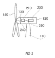
- FIG. 2 shows a schematic side view of the top of a wind energy system according to embodiments described herein.
- FIG. 3 a shows a schematic view of a transmission box with a cylinder unit according to embodiments described herein.
- FIG. 3 b shows a schematic more detailed view of a cylinder unit according to embodiments described herein.
- FIG. 3 c shows a schematic more detailed view of a cylinder unit according to further embodiments described herein.
- FIG. 3 d shows a schematic more detailed view of a cylinder unit according to further embodiments described herein.
- FIG. 4 a shows a schematic view of a drive unit or an output unit according to embodiments described herein.
- FIG. 4 b shows a schematic view of a drive unit or an output unit according to another embodiment described herein.
- FIG. 4 c shows a schematic view of a drive unit or an output unit according to further embodiments described herein.
- FIG. 4 d shows a schematic view of a drive unit or an output unit according to further embodiments described herein.
- FIG. 5 a shows a schematic plan view on the fluid working machine according to embodiments described herein.
- FIG. 5 b shows a schematic plan view on the fluid working machine according to another embodiment described herein.
- FIG. 6 shows another schematic view of a drive unit or an output unit according to embodiments described herein.
- embodiments described herein refer to a fluid-working machine with non-symmetric actuation acting as a transmission.
- a fluid-working machine allows the hydraulic energy transmission.
- different actuation principles are known, such as radial piston machines actuated by an eccentricity or axial piston machines actuated by a pivoted eccentric disc or camshaft.
- Fluid working machines are designed for optimum efficiency around a certain operation range.
- the application of fluid working machines in wind energy systems as means of main power transmission requires high efficient operation and low pressure and flow fluctuation at varying rotational speed.
- FIG. 1 is a schematic side view of a wind energy system, e.g. a wind turbine.
- the wind energy system 100 has a tower 110 to which the nacelle 120 is mounted at its top end.
- the nacelle houses a drive train (shown in FIG. 2 ) to which a generator is connected (shown in FIG. 2 ).
- a hub 130 bearing three rotor blades 140 is mounted to a lateral end of the machine nacelle 120 .
- FIG. 2 shows a more detailed view of the top of an embodiment of a wind turbine.
- the nacelle 120 houses a drive train containing the rotor hub 130 , the rotor shaft 240 , the transmission box 210 and the generator drive-shaft 250 .
- the output of the transmission box 210 is connected to a main electric generator 230 .
- the transmission box 210 is mounted between rotor hub and generator. Typically, the transmission box is placed on the rear end of the rotor shaft 240 .
- the transmission box 210 is a fluid-working machine that acts as a transmission.
- FIG. 3 a shows a closer view of an embodiment of the transmission box 210 .
- the transmission box 210 is a fluid-working machine.
- the fluid-working machine typically contains one or more cylinder units 330 and acts as a transmission.
- the rotor shaft 240 is connected to the cylinder unit 330 .
- the rotor shaft 240 is connected to or vests in the drive shaft 310 of the cylinder unit.
- the rotor shaft 240 transmits the energy absorbed by the rotor blades 140 and passes it from the rotor blades 140 to the cylinder unit 330 .
- the rotor shaft may be directly connected to the cylinder draft, or via an intermediate shaft such as the drive shaft 310 shown in FIG.
- the rotor shaft transmits the kinetic energy to the fluid working machine which may comprise several cylinder units.
- the cylinder unit 330 is connected to the generator 230 .
- an output shaft 320 is connected to the output of the cylinder unit 330 and gives the energy to the generator shaft 250 .
- the generator shaft 250 passes on the energy to the generator 230 .
- the generator changes the kinetic energy into electrical energy.
- FIG. 3 b a closer view of an embodiment of the cylinder unit 330 is shown.
- the cylinder unit 330 contains a drive unit 331 , an output unit 332 , two hydraulic connections 333 and 334 and two fluid-storages 335 and 336 .
- the storages can be pressure manifolds, for instance a low pressure manifold 335 and a high pressure manifold 336 .
- the drive shaft is connected to the drive unit 331 of the cylinder unit 330 .
- the output shaft 320 is connected to the output unit 332 .
- the drive unit 331 and the output unit 332 are connected through two hydraulic connections.
- One of them, hydraulic connection 333 is linked to a storage 335 , for instance a low pressure manifold.
- the other one, hydraulic connection 334 is linked to a storage 336 , for instance a high pressure manifold.
- the hydraulic connection between drive unit 331 and output unit 332 assures the transmission of the energy in a variable transmission ratio.
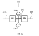
- FIG. 3 c Another embodiment is shown in FIG. 3 c .
- only one hydraulic connection 347 is given between the drive unit 331 and the output unit 332 .
- the content of the hydraulic connection 347 can be selectively valved from the storages 336 and 335 . Therefore, the same functionality is provided as explained above with regard to FIG. 3 b .
- the hydraulic connection may also be a cylinder.
- FIG. 3 d Another embodiment is shown in FIG. 3 d .
- the drive unit 331 and the output unit 332 are connected by two hydraulic connections 333 and 334 .
- Two storages 335 and 336 which are for example a low pressure manifold and a high pressure manifold, are also connected to the hydraulic connections 333 and 334 .
- the storage 335 can be connected to either hydraulic connection 333 or hydraulic connection 334 .
- both valves 349 and 350 when both valves 349 and 350 are opened, the storage 335 can be connected to both hydraulic connections 333 and 334 .
- storage 336 is also connected to both hydraulic connections 333 and 334 by means of valves 351 and 351 .
- valves 351 and 352 By valves 351 and 352 , storage 336 can be connected to either hydraulic connection 333 or hydraulic connection 334 .
- the valves 349 , 350 , 351 , and 352 may be controlled by a controller (not shown), for instance a computer.
- FIG. 4 a shows a detailed schematic cross-sectional view of an embodiment of either the drive unit 331 or the output unit 332 . Both can be designed similarly, but, in other embodiments, they are designed differently.
- the drive unit 331 or the output unit 332 there are at least two cylinders located. These are the working chambers which are shown as cylinders 337 in the embodiment of FIG. 4 a .
- the terms “cylinders” and “working chambers” are used synonymously.
- Pistons 338 can reciprocate within the cylinders 337 .
- the cylinders 337 are linked to the storage (denoted with reference number 335 in FIG. 3 b ), for instance a low pressure manifold, via a hydraulic connection 333 .
- an electromagnetically controllable valve 339 that can be a poppet valve or the like is able to separate the cylinders 337 and the storage 335 .
- the valve 339 may be positioned between cylinder 337 and hydraulic connection 333 . According to other embodiments, the valve may be placed in the hydraulic connection 333 . According to yet another embodiment, the valve may be positioned at the outlet of the storage 335 .
- a connection of the cylinders 337 with another storage (denoted with reference number 336 in FIG. 4 a ), for instance a high pressure manifold, is further provided in the drive unit/output unit.
- This is arranged through a hydraulic connection 334 and a typically electromagnetically controllable valve 340 that can be a poppet valve or the like.
- this connection is located on the side of the drive unit/output unit.
- the valve 340 may be positioned between cylinder 337 and hydraulic connection 334 . According to other embodiments, the valve may be placed in the hydraulic connection 334 . According to yet another embodiment, the valve may be positioned at the outlet of the storage 336 .
- the valves 339 and 340 are controlled by a control unit (not shown).
- the control unit is able to give signals to open or close the valves depending on the actual situation.
- the pistons 338 of the drive unit 331 or the output unit 332 are in contact to a cam 341 .
- the cam may be a ring with one or more cams. Typically, the cams are continuous on the ring.
- the ring may have an overall bending that is concave (as shown in FIG. 4 a ) or convex (as shown in FIG. 4 b ) depending on the location of the cylinders.
- the cam may have another shape for instance a plate, a chain or the like. It is further possible that the cam is a cascade of ring segments. If the embodiment shown in FIG. 4 a and 4 b is used as a drive unit, the cam 341 moves dependent on the input movement.
- the input movement is given by the shaft 342 that transmits the energy from the drive shaft 310 to the drive unit.
- Shaft 342 can be the drive shaft 310 or the rotor shaft 240 .
- the pistons 338 move according to the moving curved side of the cam.
- the surface of the cam that is directed to the pistons may be sinusoidal. Accordingly, the pistons are moving upward, that is into the cylinder, when the roller 344 is on the top of a cam and moves downward, that is out of the cylinder, when the roller 344 is in the position between two cams.
- the rotational kinetic energy is changed into hydraulic energy.
- the valve which controls the connection to the high pressure manifold is opened by the calculation unit.
- This valve is the valve 340 in the embodiment of FIG. 4 a .
- the valve which controls the connection to the low pressure manifold is opened whereas the valve connecting the cylinder to the high pressure manifold remains closed. If the embodiment shown in FIG. 4 a acts as an output unit, it operates vice versa.
- the actuation of the pistons can be caused by other means than the cam.
- a cam plate may be used.
- a chain or the like may be used.
- a crank-connecting rod-piston system can be used.
- the cam 341 is linked to the pistons 338 in order to transmit the energy given by the movement of the pistons 338 .
- the transmission ratio is, inter alia, dependent on the design, in particular on the radius of the cam, and on the control actions taken by the control unit (not shown).
- the radius of the cam is designed in a way to achieve lowest contact stresses in the overrolling elements, in order to achieve longest possible component life.
- the shaft 342 is connected to the outlet shaft 320 .
- the shaft 342 can also be the outlet shaft 320 or the generator shaft 250 .
- the outlet shaft 320 transmits the energy to the generator, e.g. via the generator shaft.
- the generator changes the kinetic rotational energy to electrical energy.
- the drive unit as well as the output unit described above can be used as a motor as well as a pump.
- the actual function is determined by the control of the control unit.
- a sequence of mode changes on successive machine cycles mixing pumping and motoring modes with idling modes allows the averaged effective flow rate into and out of the high pressure manifold 336 to be infinitely varied between full pumping flow, zero flow and full motoring flow.
- the drive unit acts as a pump and the output unit act as a motor.
- the function can be reversed.
- five operating modes of the fluid-working machine for the wind energy system are possible: full stroke pumping, part stroke pumping, full stroke motoring, part stroke motoring, and idling.
- the difference between part stroke and full stroke is the phase angle at which transitions are made from one of these states to the other relative to bottom and top dead center of the piston movement. This can be controlled by the control unit.
- the performing of the change from motor to pump mode and vice versa is typically not abrupt.
- the working chambers 337 are connected to only one hydraulic connection, as shown in FIG. 4 c , which corresponds to FIG. 3 c .
- a valve 348 regulates the amount of fluid reaching the working chamber 337 .
- the single hydraulic connection 347 is connected to both storages 335 and 336 that are, for instance, the low pressure manifold and the high pressure manifold. Additional valves may be located at the connection point of hydraulic connection 347 and storage 335 or 336 for regulating the flow of the respective content of the storages.
- a control unit is provided controlling the opening and closing of the additional valves at the connection point between hydraulic connection 347 and storages 335 or 336 .
- the control unit is able to give signals to open or close the valves depending on the actual situation. Typically, the control unit is able to actuate the additional valves depending on the given input or the desired output of the transmission box. Thereby, the flow in hydraulic connection 347 is regulated.
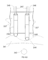
- FIG. 4 d another embodiment is shown.
- the drive unit 331 and the output unit 332 are connected by a single hydraulic connection 347 .
- the ring 341 has a convex shape.
- the number of pistons is more than two. In case the number of pistons is more than two, the pistons can be arranged in the sort shown in FIG. 5 a .
- FIG. 5 a shows a top view of a fluid-working machine.
- the pistons 338 are arranged in a circular manner in the housing 343 .
- the pistons are located around the shaft 342 , which can be connected to the output or the drive shaft.
- the shaft 342 may be the drive shaft or the output shaft.
- the pistons 338 are driven by the cam 341 .
- the pistons are typically located radially in the housing.
- the cam 5 a has an overall bending in a concave manner. According to embodiments described herein, the cam can also be bent in a convex manner as shown in FIG. 5 b . The overall bending of the cam is dependent on the location of the pistons in radial direction.
- rollers 344 roll over the cam ring 341 .
- the rollers are driven by the cam 341 that is moved by the shaft (not shown).
- the rollers 344 are in contact with the pistons 338 .
- the connection between rollers 344 and pistons 338 is flexible and movable. For instance, the rollers can roll in a sort of guidance channel 345 in the pistons. Rollers as shown in the embodiment of FIG. 6 can be used in all embodiments described herein.
- the positions of the cylinders in FIG. 6 show the on-cam position (left part of the figure) and the off-cam position (right part of the figure). These positions mark the default positions. If the piston is in the on-cam position, it is possible to block the piston by means 346 for keeping the piston in a blocked position according to embodiments described herein. Once the piston is in a blocked position, the working chamber is temporarily disabled. This may be, for instance, useful during the operation at low wind speeds. The means for keeping the piston in a blocked position are described below in more detail.
- the fluid-working machine that acts as a transmission of a wind energy system is a hydraulic machine with non-symmetric actuation.
- the non-symmetric actuation is caused by cams.
- means of temporarily disabling selected working chambers are provided. The selection of the working chambers is done by a calculation unit and depends on the actual wind situation and the desirable loads.
- the fluid working machine which is part of and adapted for the operation of a wind energy system has a characteristic behavior regarding the transient pressure, volume flow, noise and efficiency. Typically, these characteristics are dependent on the mechanical design and electronic control. By using a non-symmetric actuation of the pistons the fluctuation of pressure and flow rate is decreased and the efficiency increased.
- the control of the pistons is optimally adapted to the actual situation by a calculation unit.
- the characteristics of pressure, flow and noise can be controlled.
- Controlling allows a continual flow of the fluid in the fluid working machine thus a continual pressure characteristic and a continual and reliable energy output.
- a controlling and diminution of the fluctuation is desirable.
- the tolerance of the wind energy system regarding the irregularities in flow increases.
- the energy output becomes safer and more calculable.
- Hydraulic working machines are more efficient at high pressure levels. According to embodiments described herein, the reduction of the number of working chambers or the reduction of the volume of a working chamber is beneficial for lower torque operation in order to increase the pressure level in each working chamber and thus increase the overall efficiency of the transmission for low torque operation. This is due to the fact that hydraulic working machines are more efficient at high pressure levels. A machine designed for a specific torque experiences higher losses when operated at lower torque. Disabling the cylinders is typically controlled by the calculation unit.
- the wind energy system comprises a torque measurement device (not shown) for measuring the torque provided to the drive unit.
- the torque measurement device may allow a direct measurement of the torque exerted by the rotor, or it may calculate the torque from the generated power.
- a part of the cylinders are operating in a stationary position or an idling position when they are disabled. If they are in a stationary position, they do not move at all. For instance, they are disconnected from the cam and rest in a position with the piston totally entered into the cylinder.
- the left figure in FIG. 6 shows this embodiment, when the piston is totally entered into the cylinder. If the pistons are in the idling position, the pistons are moved upwards and downwards along with the other pistons, but there is no force exchange as there is no alternate opening of the connections to the low pressure manifold and the high pressure manifold in the respective cylinders.
- the reduction of the number of working chambers is arranged by working chamber disabling means 346 .
- the working chamber disabling means comprise mechanical blocking devices for clamping the pistons in a fixed position, for example hooks or pins that are inserted when the piston is in TDC (top dead center). Such pins may have conical tips to lift rollers completely from the cam surface. Releasing of the pistons may happen in a timing-wise coordinate fashion to avoid rollers jamming the cam.
- the working chamber disabling means comprise electromagnetic means for attracting the piston.
- the electromagnetic means include a coil that attracts a magnetic mass of the piston and/or a material attached to the cylinder.
- the control of the pistons may also be performed by the use of a Hall effect sensor.
- the working chamber disabling means make use of a pressure difference over the piston in the opposite direction than during pumping or motoring stroke. This may be done by artificially increasing the pressure at the low pressure side of the piston or by applying a low pressure at the pressure side of the piston. In some embodiments, the applied low pressure is even below atmospheric pressure. Springs may define the default position to be on-cam or off-cam as shown in FIG. 6 .
- means of controlling the actuation of the valves by electronic and/or electromagnetic means are provided such as a poppet valve made of electromagnets or the like.
- the pistons are fixed in the top dead center position when the cylinder is disabled.
- a fluid-working machine with one or more working chambers is provided that is adapted for a wind energy system.
- This fluid-working machine comprises typically a drive unit and an output unit.
- the drive unit has at least two cylinders and/or the output unit has at least two cylinders.
- the drive unit can act as a pump and/or as a motor. In standard operation of the wind energy system, the drive unit typically operates as pump.
- the output unit can act as a pump and/or as a motor. In standard operation of the wind energy system, the output unit typically operates as a motor.
- the fluid-working machine is typically used as a transmission for the wind energy system.
- the fluid-working machine allows the transformation of a rotational movement to a rotational movement at a different rotational velocity due to the cooperation of the drive unit with the output unit.
- This fluid-working machine is used with the aim of optimizing the pressure, flow, efficiency, component load and thus life and noise characteristics by non-symmetric actuation.
- Hydraulic working machines are typically more efficient at high pressure levels. Therefore, a machine which is designed for a specific torque or a specific pressure, experiences higher losses when operating at lower torque or lower pressure. For the operation mode during lower torque or lower pressure, it would be beneficial to reduce the number of active working chambers or the amount of activity of the working chambers in order to increase the pressure level in each active working chamber and thus increase the overall efficiency for low torque operation.
- hydraulic working machine in this context is used synonymously to the term “fluid working machine”.
- the temporary switching of at least one cylinder in the drive unit and/or the output unit to a predetermined state increases the efficiency of the fluid-working machine acting as transmission.
- the predetermined state may be a switches-off state or a reduced pressure state. This is particularly relevant in operational modes of the wind energy system that are considerably below the rated power, in particular in modes up to 60%, more typically up to 50% of the rated power. In those modes the operation of all pistons is not efficient. It is advantageous to switch at least one of the pistons in order to increase the pressure in the other pistons.
- the terms “switching off” and “disabling” are used synonymously herein. Switching of a part of the working chamber to a predetermined state is done in operation of the wind energy system. In particular, switching of a part of the working chambers is done while other working chambers are operating.
- the non-symmetric actuation of the fluid-working machine is caused by mechanical means for blocking or clamping the pistons of the working chambers of the fluid-working machine, by a cam for driving the working chambers of the fluid-working machine in a given motion profile or by electronically controlling the valves.
- the fluid-working machine By using the fluid-working machine with non-symmetric actuation an increase of the efficiency can be reached. Furthermore, the wind energy system, which the fluid-working machine is part of, performs better, that is, the wind energy system can cope with more irregularities in the energy flow. It might be that the physical efficiency decreases typically in the range of a percent by using a fluid-working machine as a transmission instead of a conventional gear. This percentage can be lowered by using the fluid-working machine according to embodiments described herein. Further, the economical efficiency can still increase in comparison to conventional gears. The enlargement of the economical efficiency is due to the decreasing costs for constructing and locating the fluid-working machine. Thus, it is possible to save costs in a remarkable range per Mega Watt during the lifetime of the wind energy system.
- a continuously variable fluid-working machine for a wind energy system acts as a transmission.
- the fluctuation of the energy input and consequently the output also is very high due to the varying conditions dependent on the actual wind speed and wind direction.
- it is desirable that the fluctuation of the energy yield is decreased.
- a continuously variable machine acting as a transmission as described herein can help to minimize the effects of the fluctuations on the energy output.
- a fluid-working machine with non-symmetric actuation of the pistons is used as a continuously variable transmission.
- the non-symmetric actuation can be caused e.g. by a valve train control that controls the actuation of the valve and is therefore able to block certain working chambers of the fluid working machine.
- the non-symmetric actuation can also be caused by mechanical means e.g. a non-circular cam that moves the pistons and/or is moved by the pistons.
- the drive unit as well as the output unit, as described above can act as a motor and/or as a pump.
- the function of the unit can be changed by changing the direction of actuation. Therefore, the embodiments described herein, apply to the working chambers acting as a pump as well as for the working chambers acting as a motor and vice versa.
- the number of cylinders and pistons of the fluid-working machine for the wind energy system may be more than 15, typically more than 40 and even more typically more than 60 or even 100.
- between 60 and 120 cylinders and pistons are provided in each the drive unit and the output unit.
- the cylinders are arranged on a circular arrangement.
- n is larger than 1 and chosen such that the total number of working chambers divided by n is an integer. Further, the smaller the torque, e.g. due to low wind conditions, the higher n is chosen. With very low wind conditions, it is also possible to disable e.g. 2 ⁇ 3 or 3 ⁇ 4 of all the working chambers.
- the application of a fluid-working machine acting as a transmission reduces costs for the setup of the fluid-working machine in the wind energy system due to the lower weight of the fluid-working machine and due to the lower construction costs compared to a conventional mechanical gear.
Landscapes
- Engineering & Computer Science (AREA)
- General Engineering & Computer Science (AREA)
- Mechanical Engineering (AREA)
- Life Sciences & Earth Sciences (AREA)
- Sustainable Development (AREA)
- Sustainable Energy (AREA)
- Chemical & Material Sciences (AREA)
- Combustion & Propulsion (AREA)
- Power Engineering (AREA)
- Wind Motors (AREA)
Abstract
Description
Claims (13)
Priority Applications (3)
| Application Number | Priority Date | Filing Date | Title |
|---|---|---|---|
| US12/190,746 US8074450B2 (en) | 2008-08-13 | 2008-08-13 | Wind energy system with fluid-working machine with non-symmetric actuation |
| EP09166572A EP2154368A3 (en) | 2008-08-13 | 2009-07-28 | Wind turbine with fluid power transmission arrangement |
| CN200910167405A CN101649814A (en) | 2008-08-13 | 2009-08-13 | Wind energy system with fluid-working machine with non-symmetric actuation |
Applications Claiming Priority (1)
| Application Number | Priority Date | Filing Date | Title |
|---|---|---|---|
| US12/190,746 US8074450B2 (en) | 2008-08-13 | 2008-08-13 | Wind energy system with fluid-working machine with non-symmetric actuation |
Publications (2)
| Publication Number | Publication Date |
|---|---|
| US20100040470A1 US20100040470A1 (en) | 2010-02-18 |
| US8074450B2 true US8074450B2 (en) | 2011-12-13 |
Family
ID=40933591
Family Applications (1)
| Application Number | Title | Priority Date | Filing Date |
|---|---|---|---|
| US12/190,746 Active 2030-05-13 US8074450B2 (en) | 2008-08-13 | 2008-08-13 | Wind energy system with fluid-working machine with non-symmetric actuation |
Country Status (3)
| Country | Link |
|---|---|
| US (1) | US8074450B2 (en) |
| EP (1) | EP2154368A3 (en) |
| CN (1) | CN101649814A (en) |
Cited By (6)
| Publication number | Priority date | Publication date | Assignee | Title |
|---|---|---|---|---|
| US20120060685A1 (en) * | 2010-02-23 | 2012-03-15 | Artemis Intelligent Power Limited | Variable displacement radial piston fluid working machine |
| US20120063929A1 (en) * | 2010-11-30 | 2012-03-15 | Mitsubishi Heavy Industries, Ltd. | Hydraulic pump structure for wind turbine generator or tidal current generator and method of mounting hydraulic pump |
| US20130049371A1 (en) * | 2011-08-30 | 2013-02-28 | Mitsubishi Heavy Industries, Ltd. | Oil supply in renewable energy turbine generator |
| US20130149171A1 (en) * | 2010-08-17 | 2013-06-13 | Artemis Intelligent Power Limited | Fluid-working machine with multi-lobe ring cam |
| US20200158086A1 (en) * | 2017-06-09 | 2020-05-21 | Delft Offshore Turbine B.V. | Wind turbine generator with hydraulic pump |
| WO2020123726A1 (en) * | 2018-12-11 | 2020-06-18 | Kline Robert D | Variable output, hydraulic drive system |
Families Citing this family (54)
| Publication number | Priority date | Publication date | Assignee | Title |
|---|---|---|---|---|
| US10533582B2 (en) | 2010-04-28 | 2020-01-14 | Energy Spring Ltd. | Hydraulic based efficient energy storage and regeneration system |
| US10574088B2 (en) | 2010-04-28 | 2020-02-25 | Energy Spring Ltd. | Hydraulic based efficient renewable energy storage and regeneration system |
| US10677354B2 (en) | 2010-04-28 | 2020-06-09 | Energy Spring Ltd. | Hydraulic vehicle incorporating efficient energy storage and regeneration system |
| GB2480683B (en) * | 2010-05-28 | 2014-09-10 | Artemis Intelligent Power Ltd | Method and apparatus for extracting energy from a fluctuating energy flow from a renewable energy source |
| WO2012073278A1 (en) | 2010-11-30 | 2012-06-07 | Mitsubishi Heavy Industries, Ltd. | Wind turbine generator |
| EP2454478B1 (en) * | 2010-05-28 | 2015-10-28 | Mitsubishi Heavy Industries, Ltd. | Power generating apparatus of renewable energy type and method of operating the same |
| GB2480684A (en) * | 2010-05-28 | 2011-11-30 | Artemis Intelligent Power Ltd | A method and apparatus for operating a renewable energy extraction device |
| KR20130026439A (en) | 2010-05-28 | 2013-03-13 | 미츠비시 쥬고교 가부시키가이샤 | Power generating apparatus of renewable energy type |
| JP5331250B2 (en) * | 2010-05-28 | 2013-10-30 | 三菱重工業株式会社 | Renewable energy generator |
| DE102010034188A1 (en) * | 2010-08-12 | 2012-02-16 | Mpp Gbr | Adjustable hydraulic axial piston engine, in particular for wind power plants (HPP) with hydrostatic main drive and method of control |
| GB2484888B (en) * | 2010-08-17 | 2015-01-07 | Artemis Intelligent Power Ltd | Ring cam and fluid-working machine including ring cam |
| GB2484890A (en) | 2010-08-17 | 2012-05-02 | Artemis Intelligent Power Ltd | Ring cam ensuring smooth follower handover between segments |
| US20120045327A1 (en) * | 2010-08-17 | 2012-02-23 | Artemis Intelligent Power Limited | Fluid-Working Machine with Multi-Lobe Ring Cam |
| GB2485987A (en) * | 2010-11-30 | 2012-06-06 | Mitsubishi Heavy Ind Ltd | Renewable energy extraction device tolerant of grid failures |
| GB201020264D0 (en) * | 2010-11-30 | 2011-01-12 | Mitsubishi Heavy Ind Ltd | Energy extraction device and operating method |
| AU2010257252A1 (en) | 2010-11-30 | 2012-06-14 | Mitsubishi Heavy Industries, Ltd. | Wind turbine generator system and operation control method thereof |
| WO2013042251A1 (en) | 2011-09-22 | 2013-03-28 | 三菱重工業株式会社 | Regenerated-energy power generation device and rotary wing attachment/detachment method therefor |
| CN103003567A (en) * | 2010-11-30 | 2013-03-27 | 三菱重工业株式会社 | Wind turbine generator and tidal current generator and method of operating the same |
| KR20120094414A (en) | 2010-11-30 | 2012-08-24 | 미츠비시 쥬고교 가부시키가이샤 | Wind turbine generator and tidal current generator |
| KR20130020909A (en) * | 2011-04-05 | 2013-03-04 | 미츠비시 쥬고교 가부시키가이샤 | Renewable energy generator device and hydraulic pump attachment method |
| AU2011310939A1 (en) | 2011-04-05 | 2012-10-18 | Mitsubishi Heavy Industries, Ltd. | Power generating apparatus of renewable energy type |
| CN103052795A (en) * | 2011-07-06 | 2013-04-17 | 三菱重工业株式会社 | Energy extraction device with electrical generator and method of operating energy extraction device electrical generator |
| EP2764240B1 (en) * | 2011-07-06 | 2016-03-16 | MITSUBISHI HEAVY INDUSTRIES, Ltd. | Energy extraction device, group of energy extraction devices and operating methods |
| NO332996B1 (en) * | 2011-07-20 | 2013-02-11 | Chapdrive As | Integrated hydraulic transmission for a nacelle |
| EP2582967B1 (en) * | 2011-08-30 | 2016-10-12 | MITSUBISHI HEAVY INDUSTRIES, Ltd. | Method of maintaining hydraulic pump of the hydraulic transmission in a renewable energy turbine generator and hydraulic pump in a renewable energy turbine generator |
| US20130047594A1 (en) * | 2011-08-30 | 2013-02-28 | Mitsubishi Heavy Industries, Ltd. | Cover for hydraulic pump in renewable energy turbine generator |
| EP2759700B1 (en) * | 2011-09-22 | 2016-03-30 | Mitsubishi Heavy Industries, Ltd. | Renewable energy-type electric power generation device and rotor affixation method for same |
| KR20130069720A (en) | 2011-09-22 | 2013-06-26 | 미츠비시 쥬고교 가부시키가이샤 | Renewable energy type generating apparatus and method for fixing a rotor of the same |
| JP5634595B2 (en) * | 2011-09-22 | 2014-12-03 | 三菱重工業株式会社 | Regenerative energy type power generator and rotor fixing method thereof |
| CN102384055B (en) * | 2011-10-14 | 2014-12-24 | 朱永波 | Low-rotating-speed plunger pump device and wind power generation device applying same |
| CN102384035A (en) * | 2011-10-14 | 2012-03-21 | 朱永波 | Wind energy collecting device and wind power generation system thereof |
| JP5364842B1 (en) | 2011-11-30 | 2013-12-11 | 三菱重工業株式会社 | Regenerative energy power generator and control method thereof |
| EP2607691A1 (en) * | 2011-12-22 | 2013-06-26 | Siegfried A. Eisenmann | Wind power plant with a hydraulic pump |
| KR101967148B1 (en) * | 2012-03-27 | 2019-04-10 | 한국전력공사 | Hydraulic wind power generation device and its method |
| US9261073B2 (en) | 2012-04-29 | 2016-02-16 | LGT Advanced Technology Limited | Wind energy system and method for using same |
| US9217412B2 (en) | 2012-04-29 | 2015-12-22 | LGT Advanced Technology Limited | Wind energy system and method for using same |
| WO2014002522A1 (en) | 2012-06-29 | 2014-01-03 | 三菱重工業株式会社 | Hydraulic pump, method for maintaining same, and wind power generation device |
| JP2014141957A (en) | 2012-12-28 | 2014-08-07 | Mitsubishi Heavy Ind Ltd | Radial piston hydraulic machine and wind power generator |
| JP2014129773A (en) | 2012-12-28 | 2014-07-10 | Mitsubishi Heavy Ind Ltd | Radial piston type hydraulic machine and wind power generation device |
| EP2896828B1 (en) * | 2013-02-14 | 2016-11-16 | Mitsubishi Heavy Industries, Ltd. | Wind turbine generator |
| EP2781744A3 (en) | 2013-03-18 | 2014-10-29 | Mitsubishi Heavy Industries, Ltd. | Radial piston hydraulic machine and wind turbine generator |
| JP5931844B2 (en) | 2013-12-27 | 2016-06-08 | 三菱重工業株式会社 | Diagnosis system and diagnosis method for hydraulic machine, hydraulic transmission and wind power generator |
| NL2013773B1 (en) * | 2014-11-11 | 2016-10-06 | Mecal Intellectual Property And Standards B V | Hydraulic transmission. |
| JP6308977B2 (en) * | 2015-06-11 | 2018-04-11 | 三菱重工業株式会社 | Diagnostic system for hydraulic machine, hydraulic machine, wind power generator, and diagnostic method for hydraulic machine |
| JP6434926B2 (en) | 2016-02-26 | 2018-12-05 | 三菱重工業株式会社 | Diagnostic method and diagnostic system for hydraulic machine, hydraulic machine, and renewable energy type power generator |
| JP6564338B2 (en) | 2016-02-26 | 2019-08-21 | 三菱重工業株式会社 | Diagnosis system and diagnosis method for hydraulic machine, hydraulic machine, hydraulic transmission, and renewable energy type power generator |
| JP6434927B2 (en) | 2016-02-26 | 2018-12-05 | 三菱重工業株式会社 | Diagnosis method and diagnosis system for hydraulic machine, hydraulic machine and renewable energy type power generator |
| JP6234524B1 (en) | 2016-08-26 | 2017-11-22 | 三菱重工業株式会社 | Hydraulic motor operation method, operation control system, hydraulic transmission and renewable energy power generator |
| JP6267310B1 (en) | 2016-11-17 | 2018-01-24 | 三菱重工業株式会社 | Hydraulic machine and renewable energy type power generator |
| JP6388898B2 (en) | 2016-11-17 | 2018-09-12 | 三菱重工業株式会社 | Hydraulic machine and renewable energy type power generator |
| DE102016124048A1 (en) * | 2016-12-12 | 2018-06-14 | Kamat Gmbh & Co. Kg | Axial piston pump with high flow rate at low speed and use of a piston pump in a wind turbine |
| GR1010404B (en) * | 2021-07-15 | 2023-02-10 | Αντωνιος Κωνσταντινου Μαστροκαλος | Hydrostatic rotary motor |
| EP4177462A1 (en) * | 2021-11-09 | 2023-05-10 | Terawind GmbH | Device for converting wind energy into electrical energy |
| CN115387965A (en) * | 2022-09-20 | 2022-11-25 | 三峡大学 | Efficient and reliable large-scale wind turbine generator set composite transmission system and operation control method |
Citations (9)
| Publication number | Priority date | Publication date | Assignee | Title |
|---|---|---|---|---|
| US4503673A (en) * | 1979-05-25 | 1985-03-12 | Charles Schachle | Wind power generating system |
| US4598628A (en) * | 1984-05-21 | 1986-07-08 | 4 Square Motors | Rotary hydraulic engine having oppositely disposed pistons in a scotch yoke assembly |
| US5259738A (en) * | 1988-09-29 | 1993-11-09 | University Of Edinburgh | Fluid-working machine |
| EP0494236B1 (en) | 1988-09-29 | 1995-12-13 | Artemis Intelligent Power Ltd. | Improved fluid-working machine |
| WO2004025122A1 (en) | 2002-09-12 | 2004-03-25 | Artemis Intelligent Power Limited | Fluid-working machine and operating method |
| JP2005248738A (en) * | 2004-03-02 | 2005-09-15 | Fuchu Giken:Kk | Wind power generator operation control method |
| WO2006090174A1 (en) | 2005-02-26 | 2006-08-31 | Artemis Intelligent Power Limited | Valvetrain control arrangement |
| WO2006109079A1 (en) | 2005-04-15 | 2006-10-19 | Artemis Intelligent Power Limited | Fluid-working machines |
| WO2007053036A1 (en) * | 2005-10-31 | 2007-05-10 | Chapdrive As | A turbine driven electric power production system and a method for control thereof |
Family Cites Families (2)
| Publication number | Priority date | Publication date | Assignee | Title |
|---|---|---|---|---|
| JP3368536B1 (en) * | 2001-11-08 | 2003-01-20 | 学校法人東海大学 | Fluid power generator |
| GB0614940D0 (en) * | 2006-07-27 | 2006-09-06 | Arternis Intelligent Power Ltd | Vehicle traction and stability control system employing control of fluid quanta |
-
2008
- 2008-08-13 US US12/190,746 patent/US8074450B2/en active Active
-
2009
- 2009-07-28 EP EP09166572A patent/EP2154368A3/en not_active Withdrawn
- 2009-08-13 CN CN200910167405A patent/CN101649814A/en active Pending
Patent Citations (10)
| Publication number | Priority date | Publication date | Assignee | Title |
|---|---|---|---|---|
| US4503673A (en) * | 1979-05-25 | 1985-03-12 | Charles Schachle | Wind power generating system |
| US4598628A (en) * | 1984-05-21 | 1986-07-08 | 4 Square Motors | Rotary hydraulic engine having oppositely disposed pistons in a scotch yoke assembly |
| US5259738A (en) * | 1988-09-29 | 1993-11-09 | University Of Edinburgh | Fluid-working machine |
| EP0494236B1 (en) | 1988-09-29 | 1995-12-13 | Artemis Intelligent Power Ltd. | Improved fluid-working machine |
| WO2004025122A1 (en) | 2002-09-12 | 2004-03-25 | Artemis Intelligent Power Limited | Fluid-working machine and operating method |
| EP1537333B1 (en) | 2002-09-12 | 2006-06-14 | Artemis Intelligent Power Ltd. | Fluid-working machine and operating method |
| JP2005248738A (en) * | 2004-03-02 | 2005-09-15 | Fuchu Giken:Kk | Wind power generator operation control method |
| WO2006090174A1 (en) | 2005-02-26 | 2006-08-31 | Artemis Intelligent Power Limited | Valvetrain control arrangement |
| WO2006109079A1 (en) | 2005-04-15 | 2006-10-19 | Artemis Intelligent Power Limited | Fluid-working machines |
| WO2007053036A1 (en) * | 2005-10-31 | 2007-05-10 | Chapdrive As | A turbine driven electric power production system and a method for control thereof |
Cited By (11)
| Publication number | Priority date | Publication date | Assignee | Title |
|---|---|---|---|---|
| US20120060685A1 (en) * | 2010-02-23 | 2012-03-15 | Artemis Intelligent Power Limited | Variable displacement radial piston fluid working machine |
| US9003954B2 (en) * | 2010-02-23 | 2015-04-14 | Artemis Intelligent Power Limited | Variable displacement radial piston fluid working machine |
| US20130149171A1 (en) * | 2010-08-17 | 2013-06-13 | Artemis Intelligent Power Limited | Fluid-working machine with multi-lobe ring cam |
| US9328720B2 (en) * | 2010-08-17 | 2016-05-03 | Artemis Intelligent Power Limited | Fluid-working machine with multi-lobe ring cam |
| US20120063929A1 (en) * | 2010-11-30 | 2012-03-15 | Mitsubishi Heavy Industries, Ltd. | Hydraulic pump structure for wind turbine generator or tidal current generator and method of mounting hydraulic pump |
| US8622719B2 (en) * | 2010-11-30 | 2014-01-07 | Mitsubishi Heavy Industries, Ltd. | Hydraulic pump structure for wind turbine generator or tidal current generator and method of mounting hydraulic pump |
| US20130049371A1 (en) * | 2011-08-30 | 2013-02-28 | Mitsubishi Heavy Industries, Ltd. | Oil supply in renewable energy turbine generator |
| US20200158086A1 (en) * | 2017-06-09 | 2020-05-21 | Delft Offshore Turbine B.V. | Wind turbine generator with hydraulic pump |
| WO2020123726A1 (en) * | 2018-12-11 | 2020-06-18 | Kline Robert D | Variable output, hydraulic drive system |
| US20220018366A1 (en) * | 2018-12-11 | 2022-01-20 | Robert D. Kline | Variable output, hydraulic drive system |
| US11739770B2 (en) * | 2018-12-11 | 2023-08-29 | Robert D. Kline | Variable output, hydraulic drive system |
Also Published As
| Publication number | Publication date |
|---|---|
| CN101649814A (en) | 2010-02-17 |
| US20100040470A1 (en) | 2010-02-18 |
| EP2154368A2 (en) | 2010-02-17 |
| EP2154368A3 (en) | 2012-01-04 |
Similar Documents
| Publication | Publication Date | Title |
|---|---|---|
| US8074450B2 (en) | Wind energy system with fluid-working machine with non-symmetric actuation | |
| EP2440776B1 (en) | Fluid-working machine with multi-lobe ring cam | |
| JP5463409B2 (en) | Fluid working machine and method for operating fluid working machine | |
| JP5232873B2 (en) | Wind power generator and operation control method thereof | |
| US20110142596A1 (en) | Method for monitoring a component in a hydraulic circuit, monitoring device and fluid turbine | |
| EP2326840B1 (en) | Turbine | |
| EP2454479B1 (en) | Power generating apparatus of renewable energy type | |
| EP2649348B1 (en) | Hydraulic transmission comprising variable displacement pump or motor operable with discontinuous range of displacements | |
| US20120117958A1 (en) | Method and apparatus for extracting energy from a fluctuating energy flow from a renewable energy source | |
| KR20120090760A (en) | Wind turbine generator and tidal current generator and operation method thereof | |
| US9200648B2 (en) | Fluid control valve systems, fluid systems equipped therewith, and methods of using | |
| JP5738477B2 (en) | Power generation device and method of operating pump / motor of power generation device | |
| GB2482879A (en) | Fluid-working machine with asymmetrically profiled multi-lobe ring cam | |
| JP5818967B2 (en) | Renewable energy generator with hydraulic pump capable of operation in motoring mode | |
| US20120045327A1 (en) | Fluid-Working Machine with Multi-Lobe Ring Cam | |
| EP2821648B1 (en) | Hydraulic machine and regenerative energy power generation device | |
| JP2017061885A (en) | Piston pump or power generation device | |
| CN110469511A (en) | The big transformation of constant flow adjusts centrifugal pump group |
Legal Events
| Date | Code | Title | Description |
|---|---|---|---|
| AS | Assignment |
Owner name: GE WIND ENERGY GMBH,GERMANY Free format text: ASSIGNMENT OF ASSIGNORS INTEREST;ASSIGNORS:NIES, JACOB JOHANNES;HEMMELMANN, JAN ERICH;SIGNING DATES FROM 20080709 TO 20080804;REEL/FRAME:021381/0978 Owner name: GE WIND ENERGY GMBH, GERMANY Free format text: ASSIGNMENT OF ASSIGNORS INTEREST;ASSIGNORS:NIES, JACOB JOHANNES;HEMMELMANN, JAN ERICH;SIGNING DATES FROM 20080709 TO 20080804;REEL/FRAME:021381/0978 Owner name: GENERAL ELECTRIC COMPANY,NEW YORK Free format text: ASSIGNMENT OF ASSIGNORS INTEREST;ASSIGNOR:GE WIND ENERGY GMBH;REEL/FRAME:021382/0504 Effective date: 20080806 Owner name: GENERAL ELECTRIC COMPANY, NEW YORK Free format text: ASSIGNMENT OF ASSIGNORS INTEREST;ASSIGNOR:GE WIND ENERGY GMBH;REEL/FRAME:021382/0504 Effective date: 20080806 |
|
| STCF | Information on status: patent grant |
Free format text: PATENTED CASE |
|
| FPAY | Fee payment |
Year of fee payment: 4 |
|
| MAFP | Maintenance fee payment |
Free format text: PAYMENT OF MAINTENANCE FEE, 8TH YEAR, LARGE ENTITY (ORIGINAL EVENT CODE: M1552); ENTITY STATUS OF PATENT OWNER: LARGE ENTITY Year of fee payment: 8 |
|
| MAFP | Maintenance fee payment |
Free format text: PAYMENT OF MAINTENANCE FEE, 12TH YEAR, LARGE ENTITY (ORIGINAL EVENT CODE: M1553); ENTITY STATUS OF PATENT OWNER: LARGE ENTITY Year of fee payment: 12 |
|
| AS | Assignment |
Owner name: GE INFRASTRUCTURE TECHNOLOGY LLC, SOUTH CAROLINA Free format text: ASSIGNMENT OF ASSIGNORS INTEREST;ASSIGNOR:GENERAL ELECTRIC COMPANY;REEL/FRAME:065727/0001 Effective date: 20231110 |