US8072504B2 - Method and system for aiding user alignment for capturing partially overlapping digital images - Google Patents
Method and system for aiding user alignment for capturing partially overlapping digital images Download PDFInfo
- Publication number
- US8072504B2 US8072504B2 US12/230,310 US23031008A US8072504B2 US 8072504 B2 US8072504 B2 US 8072504B2 US 23031008 A US23031008 A US 23031008A US 8072504 B2 US8072504 B2 US 8072504B2
- Authority
- US
- United States
- Prior art keywords
- image
- preview
- pixel values
- images
- pixels
- Prior art date
- Legal status (The legal status is an assumption and is not a legal conclusion. Google has not performed a legal analysis and makes no representation as to the accuracy of the status listed.)
- Active, expires
Links
- 238000000034 method Methods 0.000 title claims abstract description 45
- 239000002131 composite material Substances 0.000 claims description 29
- 238000003384 imaging method Methods 0.000 claims description 20
- 230000000881 depressing effect Effects 0.000 claims description 5
- 230000004044 response Effects 0.000 claims description 4
- 238000004091 panning Methods 0.000 claims description 2
- 238000003825 pressing Methods 0.000 description 3
- 230000008569 process Effects 0.000 description 3
- 230000000994 depressogenic effect Effects 0.000 description 2
- 238000010586 diagram Methods 0.000 description 2
- 238000009792 diffusion process Methods 0.000 description 2
- 238000005516 engineering process Methods 0.000 description 2
- 238000007667 floating Methods 0.000 description 2
- 239000004065 semiconductor Substances 0.000 description 2
- 230000004913 activation Effects 0.000 description 1
- 230000004075 alteration Effects 0.000 description 1
- 230000008859 change Effects 0.000 description 1
- 230000000295 complement effect Effects 0.000 description 1
- 239000000470 constituent Substances 0.000 description 1
- 238000007796 conventional method Methods 0.000 description 1
- 230000000694 effects Effects 0.000 description 1
- 238000009432 framing Methods 0.000 description 1
- 230000006870 function Effects 0.000 description 1
- 238000012544 monitoring process Methods 0.000 description 1
- 230000003287 optical effect Effects 0.000 description 1
- 239000007787 solid Substances 0.000 description 1
- 238000006467 substitution reaction Methods 0.000 description 1
- 238000012546 transfer Methods 0.000 description 1
- 230000007704 transition Effects 0.000 description 1
Images


Classifications
-
- H—ELECTRICITY
- H04—ELECTRIC COMMUNICATION TECHNIQUE
- H04N—PICTORIAL COMMUNICATION, e.g. TELEVISION
- H04N23/00—Cameras or camera modules comprising electronic image sensors; Control thereof
- H04N23/60—Control of cameras or camera modules
- H04N23/64—Computer-aided capture of images, e.g. transfer from script file into camera, check of taken image quality, advice or proposal for image composition or decision on when to take image
-
- G—PHYSICS
- G06—COMPUTING; CALCULATING OR COUNTING
- G06V—IMAGE OR VIDEO RECOGNITION OR UNDERSTANDING
- G06V10/00—Arrangements for image or video recognition or understanding
- G06V10/10—Image acquisition
- G06V10/16—Image acquisition using multiple overlapping images; Image stitching
Definitions
- the disclosed embodiments relate generally to digital imaging and, more particularly, to methods and systems for aiding user alignment for capturing partially overlapping digital images.
- Solid state imagers typically consist of an array of pixel cells containing photosensors. Each pixel cell produces a signal corresponding to the intensity of light impinging on its photosensor when an image of a scene is focused on the array by one or more lenses. These signals may be stored in a memory and displayed on a monitor, manipulated by software, printed, or otherwise used to provide information about the scene.
- CMOS Complementary metal-oxide-semiconductor
- CCD charge coupled device
- CMOS imagers are discussed, for example, in U.S. Pat. No. 6,140,630, U.S. Pat. No. 6,376,868, U.S. Pat. No. 6,310,366, U.S. Pat. No. 6,326,652, U.S. Pat. No. 6,204,524, and U.S. Pat. No. 6,333,205, which are all assigned to Micron Technology, Inc.
- FIG. 1 depicts an arrangement of three smaller images 101 , 102 , 103 which can be combined to form a larger composite image.
- the overlap areas 104 , 105 of the smaller images are shaded with diagonal lines.
- Overlap area 104 corresponds to an area of the scene included in both image 101 and image 102 .
- overlap area 105 corresponds to an area of the scene included in both image 102 and image 103 .
- FIG. 1 illustrates a composite image comprising three smaller images with overlapping areas.
- FIG. 2 illustrates a method of aligning two images in accordance with a disclosed embodiment.
- FIGS. 3A-D illustrate methods for aligning two images in accordance with alternative embodiments.
- FIGS. 4A and 4B illustrate methods for aligning two images in accordance with additional alternative embodiments.
- FIG. 5 illustrates a method of aligning three images in accordance with a disclosed embodiment.
- FIG. 6 is a flowchart illustrating a method of aligning an arbitrary number of images in accordance with a disclosed embodiment.
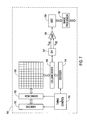
- FIG. 7 is a partial top-down block diagram of an imager and associated readout circuitry constructed in accordance with a disclosed embodiment.
- FIGS. 8A and 8B are front and back views, respectively, of a digital camera constructed in accordance with a disclosed embodiment.
- Images can be better aligned during imaging by superimposing on a display (e.g., the display on a digital camera) a portion of a previously captured image over a preview of the next image to be captured (or, conversely, a portion of the preview of the next image could be superimposed over the previously captured image).
- the imager can then be adjusted as a user views the display to bring the images into better alignment. For example, a user operating a digital camera would capture a first image (e.g., by pressing a shutter release button). A portion of the first image would be overlaid atop a live preview of a second image. The user could then pan or rotate the digital camera to bring the first and second images into better alignment before depressing the shutter button again to capture the second image.
- FIG. 2 illustrates an arrangement of first and second image portions in accordance with a disclosed embodiment.
- Image 202 is a previously captured first image.
- Image 201 is the current image (e.g., the image sought to be aligned with the first image).
- the current image 201 represents the image that will be captured when the shutter release button is depressed.
- a live preview of image 201 shown on a display of the digital camera can be continuously updated based on the position of the camera. Typically, the live preview would be displayed on an LCD or other monitor on the rear of the digital camera or in the digital camera's viewfinder.
- the thick line surrounding the current image 201 defines the area preferably displayed on the monitor.
- the checkerboard pattern displayed on the left side of current image 201 corresponds to the intended overlap area between previously captured image 202 and current image 201 .
- the checkerboard pattern consists of tiles 203 and “clear” areas 204 .
- the tiles 203 which are denoted by diagonal line shading, each comprise a group of pixels from the previously captured image 202 overlaid atop the live preview of the current image 201 .
- the clear areas 204 each comprise a group of pixels from the live preview of the current image that “show through” in-between the tiles 203 .
- a user can bring the images 201 and 202 into better alignment by adjusting the digital camera until the portions of the scene in previously captured tiles 203 appear to be aligned with the portions of the scene in areas 204 . Once the user is satisfied with the alignment, the current image can be captured (e.g., by depressing the shutter release button).
- images 201 and 202 could be reversed (i.e., image 201 could be the previously captured image and image 202 could be a live preview representing the image that will be captured when the shutter released button is depressed).
- tiles 203 could be continuously updated with the live preview image while tiles 204 would statically display the previously captured image.
- FIG. 2 illustrates a simple checkerboard pattern with alternating tiles of pixels from a previously captured image and areas of the current image
- FIGS. 3A-D illustrate four of the many possible alternative patterns.
- FIG. 3A comprises a current image 310 overlaid with tiles 311 , 312 , 313 each comprising a group of pixels from a previously captured image.
- a first column in the intended overlap area comprises relatively small tiles 311 arranged in a checkerboard pattern.
- a second column in the intended overlap area comprises a single large tile 312 .
- a third column in the intended overlap area comprises several medium-size tiles 313 larger than those in the first column, but smaller than the tile 312 in the second column.
- FIG. 3B illustrates an image 320 and similar tiles 321 , 322 , 323 as FIG. 3A , but arranged with the second and third columns swapped.
- FIG. 3C illustrates a similar checkerboard pattern as FIG. 2 .
- the tiles 331 overlaid on the image 330 of FIG. 3C are smaller (i.e., comprise fewer pixels) and more numerous.
- the tiles 331 could comprise a few pixels or even a single pixel.
- Tiles 331 each comprising only a single pixel can be used to simulate a partially transparent second image at reduced computational complexity compared to conventional methods that compute new “merged” pixel values based on a combination of pixel values from the first and second images.
- FIG. 3D illustrates yet another embodiment of the checkerboard pattern wherein the tiles 341 overlaid on the image 340 are larger (i.e., each tile 341 comprises more pixels) and less numerous than those of FIGS. 2 and 3C .
- FIG. 4A illustrates an alternative positioning of tiles 411 , each comprising a group of pixels from a previously captured frame, within an image 410 . More specifically, the tiles 411 are located on the right side of the image 410 rather than the left side, as illustrated in FIGS. 2 and 3 A-D. This configuration might be useful, for example, if images comprising the composite image are captured from right-to-left, rather than from left-to-right.
- FIG. 4B illustrates tiles 421 positioned at the top of an image 420 . This configuration might be useful, for example, if images to be used in creating the composite image are captured from top-to-bottom. Of course, tiles could also be positioned at the bottom of an image to facilitate capture of images comprising the composite image from bottom-to-top.
- FIG. 5 illustrates an alternative embodiment in which more than two images can be aligned simultaneously.
- three images a left image 501 , a center image 500 and a right image 502 —are aligned.
- other embodiments could comprise any number of images and the images need not be arranged linearly but could also include images to the top and bottom, as described above with reference to FIGS. 4A and 4B .
- Any one or more of the images could be live preview images.
- center image 500 could be a previously captured image
- left image 501 is a live preview from a first camera
- right image 502 is a live preview from a second camera.
- a processor within the personal computer could then combine the two live preview stream with the previously captured image to form the display illustrated in FIG. 5 , which could then be displayed to a user (e.g., on a conventional LCD monitor attached to the personal computer).
- the first camera can be adjusted to bring the left live preview image 501 into better alignment with the previously captured center image 500 .
- the second camera can be adjusted to bring the right live preview image 502 into better alignment with the previously captured center image 500 .
- the tiles in FIGS. 2 , 3 A-D, 4 A, 4 B, and 5 are illustrated as squares, other configurations are possible.
- the tiles might be rectangular (i.e., comprise a block of pixels arranged in an M ⁇ N pattern where M does not equal N).
- the tiles have an aspect ratio similar to that of the image.
- a typical photograph has an aspect ratio of about 3-to-2 (i.e., a width of 3 units and height of 2 units).
- Tiles could be configured similarly (e.g., 30 pixels in width and 20 pixels in height).
- tile patterns are expressly disclosed herein, but many other arrangements are possible.
- a user can select from among a plurality of pre-defined tile patterns, or even create a custom tile pattern, for use when aligning images during imaging.
- a digital camera might allow a user to select a pattern via a toggle switch, a configuration menu, a touch screen, or a button for changing patterns before or during imaging.
- the tiles can be adjusted.
- tiles associated with a previously captured image could be darkened or lightened.
- the color of tiles could be altered (e.g., tinted red).
- each of the red (R), green (G), and blue (B) values associated with pixels in the tiles could be reduced by 40.
- a medium green pixel in the previously captured image having an RGB value of (100, 250, 50) could be displayed as having an RGB value of (60, 210, 10), which corresponds to a darker shade of green.
- the color of the pixel values can be adjusted (i.e., the tiles can be “tinted”) by changing only one or two of the RGB values, or by changing the RGB values in different amounts.
- FIG. 6 illustrates a method 600 of aligning an arbitrary number of images in accordance with a disclosed embodiment.
- a first image is captured.
- step 601 might involve a user framing an image in the camera's viewfinder or display area, then depressing the shutter release button.
- the previous image and a live preview of the next image are displayed (e.g., in the display area of the digital camera). For example, a portion of the previous image could be displayed in a checkerboard pattern atop a live preview of the next image, as described above with reference to FIG. 2 .
- any other pattern for example those described above with reference to FIGS. 3A-D and 4 A-B could also be used.
- the user aligns the previous and next images based on the display (e.g., by panning or rotating the digital camera and monitoring the resulting change in alignment).
- the second image is captured at step 604 .
- the user can indicate satisfactory alignment by, for example, depressing a shutter release button.
- it is determined whether additional images are to be captured e.g., by the user pressing an appropriate button on the digital camera). If more images are to be captured, then the method continues at step 602 with alignment of the next image.
- a composite image can be generated from the captured images.
- the captured images can be transferred to a processor system that generates the composite image at step 607 using known compositing techniques and outputs the composite image at step 608 .
- Steps 607 and 608 could be performed by the image processor of an imaging system that captures the images (e.g., a digital camera), or by a separate processor system that receives and processes the captured images (e.g., a personal computer).
- a composite image can be generated after each of the second and subsequent images is captured (i.e., after step 604 ).
- This intermediate composite image could then be used as the previous image displayed at step 602 .
- the composite image can be generated by the imaging device (e.g., the digital camera) that captures the images or by another processor system (e.g., a personal computer) that receives the captured images from the imaging device. If the composite image is to be generated by another processor system, then the captured images are transferred (e.g., via USB, FireWire, WiFi, portable memory card, or another other known data transfer technology) from the imaging device to the processor system at optional step 606 .
- the composite image is output to a storage medium (e.g., printed, burned to a CD, or stored in a computer memory, such as RAM or a hard disk) at step 608 . If the user is not satisfied with the composite image (e.g., because the captured images are not sufficiently aligned), the method can be repeated (i.e., begin again at step 601 ) to generate another composite image.
- a storage medium e.g., printed, burned to a CD, or stored in a computer memory, such as RAM or a hard disk
- FIG. 7 is a partial block diagram view of an imager 700 (e.g., a CMOS imager) and associated read-out circuitry constructed in accordance with an embodiment disclosed herein.
- an imager 700 e.g., a CMOS imager
- FIG. 7 illustrates a CMOS imager and associated read-out circuitry
- embodiments may include other types of imagers, for example a CCD imager.
- the pixel cells in each row of pixel array 706 are all turned on at the same time by a row select line, and the signals of the pixel cells of each column are selectively output onto output lines by respective column select lines.
- a plurality of row and column select lines are provided for the array.
- the row lines are selectively activated in sequence by a row driver 703 in response to a row address decoder 702 and the column select lines are selectively activated in sequence for each row activation by a column driver 705 in response to a column address decoder 704 .
- row and column addresses are provided for each pixel cell of the pixel array 706 .
- the imager 700 is operated by the timing and control circuit 701 , which controls the address decoders 702 , 704 for selecting the appropriate row and column select lines for pixel cell read-out, and the row and column drivers 703 , 705 , which apply driving voltage to the drive transistors of the selected row and column lines.
- the pixel cell output signals typically include a pixel reset signal V rst taken off of a floating diffusion region (via a source follower transistor) when it is reset and a pixel image signal V sig , which is taken off the floating diffusion region (via the source follower transistor) after charges generated by an image are transferred to it.
- the V rst and V sig signals for each pixel of pixel array 706 are read by a sample and hold circuit 707 and are subtracted by a differential amplifier 708 that produces a difference signal (V rst ⁇ V sig ) for each pixel cell of pixel array 706 , which represents the amount of light impinging on the pixel cell.
- This signal difference is digitized by an analog-to-digital converter (ADC) 709 .
- ADC analog-to-digital converter
- the digitized pixel signals are then fed to an image processor 710 which processes the pixel signals and forms a digital image output. It is also possible to have separate driver and read-out circuits for each sub-array with the pixel output signal from the ADC 709 of each sub-array feeding into a common image processor circuit 710 .
- the imager 700 is formed on a single semiconductor chip, although other configurations are possible. As known in the art, imager 700 can provide continuous frames of images, with one frame being captured when a shutter release button is pressed. Thus, after one image is captured by the imager 700 , the next series of preview frames can be provided to a display device for superimposition of the captured image, as described above.
- FIG. 8A depicts a processor system 800 constructed in accordance with a disclosed embodiment.
- the processor system 800 is a digital camera, which comprises the imager 700 described above.
- the system 800 also includes a lens 801 for focusing an image on the pixel array 706 of imaging device 700 .
- System 800 also comprises the CPU 804 , such as a microprocessor that controls camera functions and image flow, and communicates with an input/output (I/O) device 805 over a bus 803 .
- the imaging device 700 can communicate with the CPU 804 over the bus 803 .
- the system 800 also includes random access memory (RAM) 808 , and can include removable memory 806 , such as flash memory, which also communicates with the CPU 804 over the bus 803 .
- the imaging device 700 may be combined with the CPU 804 on a single chip or may be implemented on separate chips.
- FIG. 8B illustrates the rear of the digital camera illustrated in FIG. 8A .
- the digital camera 800 comprises a display 809 used to display an alignment preview image, generated from a captured image and preview images from imaging device 700 , to a user.
- an alignment preview image could be displayed in a viewfinder 812 .
- the digital camera 800 can also include a input device, such as directional switch 811 , to facilitate user input.
- a user could use the input device 811 to select among a plurality of tile patterns available for use in the alignment preview image.
- tiles 810 arranged in a checkerboard pattern are shown along the left side of the display.
- Tiles 810 could each comprise a group of pixels from a previously captured image while the remainder of the display comprises pixels from a preview of a next image to be captured. Of course, many other tile arrangements as possible, as described above.
- a user can adjust the pan and tilt of the digital camera as necessary to bring the images into better aligned. Once the images are satisfactorily aligned, the user can capture the second image by, for example, pressing the shutter release button 802 illustrated in FIG. 8A .
- an image processor typically receives pixel signal values from a pixel array 706 and associated readout circuitry.
- the image processor combines many pixel signal values to form an image.
- the image can then be transferred, (e.g., via bus 803 illustrated in FIG. 8A ) to a memory (e.g., RAM 808 ).
- a memory e.g., RAM 808 .
- the CPU 804 can generate an alignment preview image by combining one or more captured images with a preview image, as described above, by reading the images out of RAM 808 or receiving them directly from the imager 700 via the bus 803 .
- the alignment preview image can then be shown to a user on the display 809 illustrated in FIG. 8B .
- the CPU 804 can continuously update the alignment preview image with newly captured images received from the image processor 710 to illustrate the effects of imager motion to the user in real-time.
- the system 800 is a personal computer comprising a CPU 804 , which communicates with an I/O device 805 and RAM 808 over the bus 803 .
- the system 800 does not necessarily include an imaging device 700 .
- digital pixel values can be transferred from another device (e.g., a digital video camera) via the I/O device 805 , which might be, for example, a USB port, a memory card reader, a network port, a parallel port, a serial port, a FireWire port, a floppy disk drive, an optical disk drive, or a wireless transceiver.
- the corresponding digital pixel values can be transferred to the personal computer 800 via the I/O device 805 .
- a live preview of the next image could be streamed (e.g., as a streaming MPEG or RealMedia video) to the personal computer 800 via the I/O device 805 .
- the CPU 804 can generate a live preview image based on the digital pixel values received via the I/O device 805 (e.g., by superimposing pixel values associated with the live preview on the captured image).
- the alignment preview image can be shown to the user on a display associated with the personal computer 800 (e.g., a conventional LCD monitor), such as described above with reference to FIG. 2 .
- the user can then adjust the source of the digital pixel values (e.g., the digital video camera) either directly or, if the source is remote, then via remote control over a communications network such as the Internet.
- the next image is captured and associated digital pixel values are transferred to the personal computer 800 via the I/O device 805 .
- the image can then be stored in a memory of the personal computer 800 (e.g., the RAM 806 , the removable memory 806 , or a hard disk drive).
- the CPU 804 can generate a composite image based on the images stored in the memory of the personal computer 800 and store the resulting composite image in the memory or output it to another medium (e.g., a conventional LCD display, removable media, or a printer) or both.
Landscapes
- Engineering & Computer Science (AREA)
- Multimedia (AREA)
- Signal Processing (AREA)
- Studio Devices (AREA)
Abstract
Description
Claims (32)
Priority Applications (1)
| Application Number | Priority Date | Filing Date | Title |
|---|---|---|---|
| US12/230,310 US8072504B2 (en) | 2008-08-27 | 2008-08-27 | Method and system for aiding user alignment for capturing partially overlapping digital images |
Applications Claiming Priority (1)
| Application Number | Priority Date | Filing Date | Title |
|---|---|---|---|
| US12/230,310 US8072504B2 (en) | 2008-08-27 | 2008-08-27 | Method and system for aiding user alignment for capturing partially overlapping digital images |
Publications (2)
| Publication Number | Publication Date |
|---|---|
| US20100053353A1 US20100053353A1 (en) | 2010-03-04 |
| US8072504B2 true US8072504B2 (en) | 2011-12-06 |
Family
ID=41724799
Family Applications (1)
| Application Number | Title | Priority Date | Filing Date |
|---|---|---|---|
| US12/230,310 Active 2030-04-11 US8072504B2 (en) | 2008-08-27 | 2008-08-27 | Method and system for aiding user alignment for capturing partially overlapping digital images |
Country Status (1)
| Country | Link |
|---|---|
| US (1) | US8072504B2 (en) |
Cited By (3)
| Publication number | Priority date | Publication date | Assignee | Title |
|---|---|---|---|---|
| US20100239183A1 (en) * | 2007-06-06 | 2010-09-23 | Olivier Martinet | Method and a device for producing a composite image or a composite sequence of images inducing enhanced perception of the relief of at least one subject |
| US20130063551A1 (en) * | 2008-09-16 | 2013-03-14 | Altia System Inc | Synchronized Multiple Imager System and Method |
| US10148884B2 (en) | 2016-07-29 | 2018-12-04 | Microsoft Technology Licensing, Llc | Facilitating capturing a digital image |
Families Citing this family (14)
| Publication number | Priority date | Publication date | Assignee | Title |
|---|---|---|---|---|
| US7970625B2 (en) | 2004-11-04 | 2011-06-28 | Dr Systems, Inc. | Systems and methods for retrieval of medical data |
| US7660488B2 (en) | 2004-11-04 | 2010-02-09 | Dr Systems, Inc. | Systems and methods for viewing medical images |
| US7920152B2 (en) | 2004-11-04 | 2011-04-05 | Dr Systems, Inc. | Systems and methods for viewing medical 3D imaging volumes |
| US7885440B2 (en) * | 2004-11-04 | 2011-02-08 | Dr Systems, Inc. | Systems and methods for interleaving series of medical images |
| US7787672B2 (en) | 2004-11-04 | 2010-08-31 | Dr Systems, Inc. | Systems and methods for matching, naming, and displaying medical images |
| US7953614B1 (en) | 2006-11-22 | 2011-05-31 | Dr Systems, Inc. | Smart placement rules |
| US8380533B2 (en) | 2008-11-19 | 2013-02-19 | DR Systems Inc. | System and method of providing dynamic and customizable medical examination forms |
| US8712120B1 (en) | 2009-09-28 | 2014-04-29 | Dr Systems, Inc. | Rules-based approach to transferring and/or viewing medical images |
| US9792012B2 (en) | 2009-10-01 | 2017-10-17 | Mobile Imaging In Sweden Ab | Method relating to digital images |
| US9544498B2 (en) * | 2010-09-20 | 2017-01-10 | Mobile Imaging In Sweden Ab | Method for forming images |
| US9092727B1 (en) | 2011-08-11 | 2015-07-28 | D.R. Systems, Inc. | Exam type mapping |
| US9026615B1 (en) * | 2011-09-22 | 2015-05-05 | Teradici Corporation | Method and apparatus for caching image data transmitted over a lossy network |
| US9495604B1 (en) | 2013-01-09 | 2016-11-15 | D.R. Systems, Inc. | Intelligent management of computerized advanced processing |
| US10929508B2 (en) | 2015-04-30 | 2021-02-23 | Merge Healthcare Solutions Inc. | Database systems and interactive user interfaces for dynamic interaction with, and indications of, digital medical image data |
Citations (24)
| Publication number | Priority date | Publication date | Assignee | Title |
|---|---|---|---|---|
| GB2262680A (en) | 1991-12-18 | 1993-06-23 | Ampex Systems Corp | Video special effects system |
| US6041361A (en) * | 1996-10-31 | 2000-03-21 | Sensormatic Electronics Corporation | Digital video recorder providing separate pipelining for odd and even fields from a single camera |
| US6310650B1 (en) | 1998-09-23 | 2001-10-30 | Honeywell International Inc. | Method and apparatus for calibrating a tiled display |
| US20030063208A1 (en) * | 1996-06-12 | 2003-04-03 | Nikon Corporation | Image pick-up apparatus |
| US20030184778A1 (en) * | 2002-03-28 | 2003-10-02 | Sanyo Electric Co., Ltd. | Image processing method, image processing apparatus, computer program product and computer memory product |
| US6681056B1 (en) | 1999-03-30 | 2004-01-20 | International Business Machines Corporation | Method and system for digital image acquisition and continuous zoom display from multiple resolutional views using a heterogeneous image pyramid representation |
| US20040218833A1 (en) * | 1997-09-10 | 2004-11-04 | Koichi Ejiri | System and method for displaying an image indicating a positional relation between partially overlapping images |
| US20050088534A1 (en) * | 2003-10-24 | 2005-04-28 | Junxing Shen | Color correction for images forming a panoramic image |
| US20050140809A1 (en) * | 2003-12-24 | 2005-06-30 | Samsung Electronics Co., Ltd. | Picture quality evaluation device and controlling method thereof |
| US20060050152A1 (en) * | 2004-09-03 | 2006-03-09 | Rai Barinder S | Method for digital image stitching and apparatus for performing the same |
| US7024054B2 (en) * | 2002-09-27 | 2006-04-04 | Eastman Kodak Company | Method and system for generating a foreground mask for a composite image |
| US20060072176A1 (en) | 2004-09-29 | 2006-04-06 | Silverstein D A | Creating composite images based on image capture device poses corresponding to captured images |
| US20060115182A1 (en) | 2004-11-30 | 2006-06-01 | Yining Deng | System and method of intensity correction |
| US20060115181A1 (en) | 2004-11-30 | 2006-06-01 | Yining Deng | System and method of aligning images |
| US20060181619A1 (en) * | 2005-02-11 | 2006-08-17 | Creative Technology, Ltd. | Method and apparatus for forming a panoramic image |
| US20060187234A1 (en) * | 2005-02-18 | 2006-08-24 | Yining Deng | System and method for blending images |
| US20060239571A1 (en) * | 2005-03-29 | 2006-10-26 | Shenzhen Mindray Bio-Medical Electronics Co., Ltd. | Method of volume-panorama imaging processing |
| US7162102B2 (en) | 2001-12-19 | 2007-01-09 | Eastman Kodak Company | Method and system for compositing images to produce a cropped image |
| US20070146530A1 (en) * | 2005-12-28 | 2007-06-28 | Hiroyasu Nose | Photographing apparatus, image display method, computer program and storage medium |
| US7239805B2 (en) | 2005-02-01 | 2007-07-03 | Microsoft Corporation | Method and system for combining multiple exposure images having scene and camera motion |
| US20070242940A1 (en) * | 2004-01-30 | 2007-10-18 | Naoto Yumiki | Lens Barrel and Image Device Provided with Lens Barrel, and Assembly Method of Lens Barrel |
| US7289147B2 (en) | 2004-02-03 | 2007-10-30 | Hewlett-Packard Development Company, L.P. | Method for providing image alignment feedback for panorama (composite) images in digital cameras using edge detection |
| US20080074489A1 (en) * | 2006-09-27 | 2008-03-27 | Samsung Electronics Co., Ltd. | Apparatus, method, and medium for generating panoramic image |
| US20080211942A1 (en) * | 2003-10-20 | 2008-09-04 | Creo Israel Limited | Method and Design for Using Multiple Outputs of Image Sensor |
-
2008
- 2008-08-27 US US12/230,310 patent/US8072504B2/en active Active
Patent Citations (24)
| Publication number | Priority date | Publication date | Assignee | Title |
|---|---|---|---|---|
| GB2262680A (en) | 1991-12-18 | 1993-06-23 | Ampex Systems Corp | Video special effects system |
| US20030063208A1 (en) * | 1996-06-12 | 2003-04-03 | Nikon Corporation | Image pick-up apparatus |
| US6041361A (en) * | 1996-10-31 | 2000-03-21 | Sensormatic Electronics Corporation | Digital video recorder providing separate pipelining for odd and even fields from a single camera |
| US20040218833A1 (en) * | 1997-09-10 | 2004-11-04 | Koichi Ejiri | System and method for displaying an image indicating a positional relation between partially overlapping images |
| US6310650B1 (en) | 1998-09-23 | 2001-10-30 | Honeywell International Inc. | Method and apparatus for calibrating a tiled display |
| US6681056B1 (en) | 1999-03-30 | 2004-01-20 | International Business Machines Corporation | Method and system for digital image acquisition and continuous zoom display from multiple resolutional views using a heterogeneous image pyramid representation |
| US7162102B2 (en) | 2001-12-19 | 2007-01-09 | Eastman Kodak Company | Method and system for compositing images to produce a cropped image |
| US20030184778A1 (en) * | 2002-03-28 | 2003-10-02 | Sanyo Electric Co., Ltd. | Image processing method, image processing apparatus, computer program product and computer memory product |
| US7024054B2 (en) * | 2002-09-27 | 2006-04-04 | Eastman Kodak Company | Method and system for generating a foreground mask for a composite image |
| US20080211942A1 (en) * | 2003-10-20 | 2008-09-04 | Creo Israel Limited | Method and Design for Using Multiple Outputs of Image Sensor |
| US20050088534A1 (en) * | 2003-10-24 | 2005-04-28 | Junxing Shen | Color correction for images forming a panoramic image |
| US20050140809A1 (en) * | 2003-12-24 | 2005-06-30 | Samsung Electronics Co., Ltd. | Picture quality evaluation device and controlling method thereof |
| US20070242940A1 (en) * | 2004-01-30 | 2007-10-18 | Naoto Yumiki | Lens Barrel and Image Device Provided with Lens Barrel, and Assembly Method of Lens Barrel |
| US7289147B2 (en) | 2004-02-03 | 2007-10-30 | Hewlett-Packard Development Company, L.P. | Method for providing image alignment feedback for panorama (composite) images in digital cameras using edge detection |
| US20060050152A1 (en) * | 2004-09-03 | 2006-03-09 | Rai Barinder S | Method for digital image stitching and apparatus for performing the same |
| US20060072176A1 (en) | 2004-09-29 | 2006-04-06 | Silverstein D A | Creating composite images based on image capture device poses corresponding to captured images |
| US20060115182A1 (en) | 2004-11-30 | 2006-06-01 | Yining Deng | System and method of intensity correction |
| US20060115181A1 (en) | 2004-11-30 | 2006-06-01 | Yining Deng | System and method of aligning images |
| US7239805B2 (en) | 2005-02-01 | 2007-07-03 | Microsoft Corporation | Method and system for combining multiple exposure images having scene and camera motion |
| US20060181619A1 (en) * | 2005-02-11 | 2006-08-17 | Creative Technology, Ltd. | Method and apparatus for forming a panoramic image |
| US20060187234A1 (en) * | 2005-02-18 | 2006-08-24 | Yining Deng | System and method for blending images |
| US20060239571A1 (en) * | 2005-03-29 | 2006-10-26 | Shenzhen Mindray Bio-Medical Electronics Co., Ltd. | Method of volume-panorama imaging processing |
| US20070146530A1 (en) * | 2005-12-28 | 2007-06-28 | Hiroyasu Nose | Photographing apparatus, image display method, computer program and storage medium |
| US20080074489A1 (en) * | 2006-09-27 | 2008-03-27 | Samsung Electronics Co., Ltd. | Apparatus, method, and medium for generating panoramic image |
Non-Patent Citations (2)
| Title |
|---|
| "What is Panorama Photography?", 2005 Hewlett-Packard Dev. Co. (Brochure). |
| Tsai, Chia-Ling et al., "A Correspondence-Based Software Toolkit for Image Registration". |
Cited By (4)
| Publication number | Priority date | Publication date | Assignee | Title |
|---|---|---|---|---|
| US20100239183A1 (en) * | 2007-06-06 | 2010-09-23 | Olivier Martinet | Method and a device for producing a composite image or a composite sequence of images inducing enhanced perception of the relief of at least one subject |
| US20130063551A1 (en) * | 2008-09-16 | 2013-03-14 | Altia System Inc | Synchronized Multiple Imager System and Method |
| US8717448B2 (en) * | 2008-09-16 | 2014-05-06 | Altia Systems, Inc. | Synchronized multiple imager system and method |
| US10148884B2 (en) | 2016-07-29 | 2018-12-04 | Microsoft Technology Licensing, Llc | Facilitating capturing a digital image |
Also Published As
| Publication number | Publication date |
|---|---|
| US20100053353A1 (en) | 2010-03-04 |
Similar Documents
| Publication | Publication Date | Title |
|---|---|---|
| US8072504B2 (en) | Method and system for aiding user alignment for capturing partially overlapping digital images | |
| US11206353B2 (en) | Electronic apparatus, method for controlling electronic apparatus, and control program for setting image-capture conditions of image sensor | |
| EP3588940B1 (en) | Electronic apparatus, method for controlling electronic apparatus, and control program | |
| US20160112644A1 (en) | Electronic apparatus and control program | |
| US7609306B2 (en) | Solid-state image pickup apparatus with high- and low-sensitivity photosensitive cells, and an image shooting method using the same | |
| JP2017216646A (en) | Imaging device, imaging apparatus and imaging signal processing method | |
| US20080043132A1 (en) | Method and apparatus for displaying a power-up image on an imaging device upon power-up | |
| US12075169B2 (en) | Image sensor and imaging device | |
| JP4639406B2 (en) | Imaging device | |
| JP4967432B2 (en) | Imaging apparatus and camera system | |
| JP6758946B2 (en) | Imaging device and playback device | |
| JP2020053771A (en) | Image processing apparatus and imaging apparatus | |
| JP2008109485A (en) | Imaging apparatus and imaging control method | |
| JP2006129418A (en) | Method for driving charge-transfer type solid-state image pick-up device and image pick-up method and apparatus | |
| JP6296767B2 (en) | Imaging apparatus and image signal processing method | |
| JP2006166132A (en) | Camera and luminance distribution display method | |
| JP2006340100A (en) | Photographic device | |
| JP4630200B2 (en) | Solid-state imaging device and imaging apparatus | |
| JP7283488B2 (en) | Image sensor and electronic equipment | |
| JP7324866B2 (en) | Imaging device | |
| JP7176591B2 (en) | Electronics | |
| JP2023054229A (en) | Electronic apparatus | |
| JP2006287912A (en) | Solid-state imaging element and imaging apparatus | |
| JP2009268079A (en) | Imaging apparatus, and driving method thereof |
Legal Events
| Date | Code | Title | Description |
|---|---|---|---|
| AS | Assignment |
Owner name: MICRON TECHNOLOGY, INC.,IDAHO Free format text: ASSIGNMENT OF ASSIGNORS INTEREST;ASSIGNORS:HUNTER, GREGORY M.;SACHS, TODD;REEL/FRAME:021493/0449 Effective date: 20080821 Owner name: MICRON TECHNOLOGY, INC., IDAHO Free format text: ASSIGNMENT OF ASSIGNORS INTEREST;ASSIGNORS:HUNTER, GREGORY M.;SACHS, TODD;REEL/FRAME:021493/0449 Effective date: 20080821 |
|
| FEPP | Fee payment procedure |
Free format text: PAYOR NUMBER ASSIGNED (ORIGINAL EVENT CODE: ASPN); ENTITY STATUS OF PATENT OWNER: LARGE ENTITY |
|
| STCF | Information on status: patent grant |
Free format text: PATENTED CASE |
|
| FPAY | Fee payment |
Year of fee payment: 4 |
|
| AS | Assignment |
Owner name: U.S. BANK NATIONAL ASSOCIATION, AS COLLATERAL AGENT, CALIFORNIA Free format text: SECURITY INTEREST;ASSIGNOR:MICRON TECHNOLOGY, INC.;REEL/FRAME:038669/0001 Effective date: 20160426 Owner name: U.S. BANK NATIONAL ASSOCIATION, AS COLLATERAL AGEN Free format text: SECURITY INTEREST;ASSIGNOR:MICRON TECHNOLOGY, INC.;REEL/FRAME:038669/0001 Effective date: 20160426 |
|
| AS | Assignment |
Owner name: MORGAN STANLEY SENIOR FUNDING, INC., AS COLLATERAL AGENT, MARYLAND Free format text: PATENT SECURITY AGREEMENT;ASSIGNOR:MICRON TECHNOLOGY, INC.;REEL/FRAME:038954/0001 Effective date: 20160426 Owner name: MORGAN STANLEY SENIOR FUNDING, INC., AS COLLATERAL Free format text: PATENT SECURITY AGREEMENT;ASSIGNOR:MICRON TECHNOLOGY, INC.;REEL/FRAME:038954/0001 Effective date: 20160426 |
|
| AS | Assignment |
Owner name: U.S. BANK NATIONAL ASSOCIATION, AS COLLATERAL AGENT, CALIFORNIA Free format text: CORRECTIVE ASSIGNMENT TO CORRECT THE REPLACE ERRONEOUSLY FILED PATENT #7358718 WITH THE CORRECT PATENT #7358178 PREVIOUSLY RECORDED ON REEL 038669 FRAME 0001. ASSIGNOR(S) HEREBY CONFIRMS THE SECURITY INTEREST;ASSIGNOR:MICRON TECHNOLOGY, INC.;REEL/FRAME:043079/0001 Effective date: 20160426 Owner name: U.S. BANK NATIONAL ASSOCIATION, AS COLLATERAL AGEN Free format text: CORRECTIVE ASSIGNMENT TO CORRECT THE REPLACE ERRONEOUSLY FILED PATENT #7358718 WITH THE CORRECT PATENT #7358178 PREVIOUSLY RECORDED ON REEL 038669 FRAME 0001. ASSIGNOR(S) HEREBY CONFIRMS THE SECURITY INTEREST;ASSIGNOR:MICRON TECHNOLOGY, INC.;REEL/FRAME:043079/0001 Effective date: 20160426 |
|
| AS | Assignment |
Owner name: JPMORGAN CHASE BANK, N.A., AS COLLATERAL AGENT, ILLINOIS Free format text: SECURITY INTEREST;ASSIGNORS:MICRON TECHNOLOGY, INC.;MICRON SEMICONDUCTOR PRODUCTS, INC.;REEL/FRAME:047540/0001 Effective date: 20180703 Owner name: JPMORGAN CHASE BANK, N.A., AS COLLATERAL AGENT, IL Free format text: SECURITY INTEREST;ASSIGNORS:MICRON TECHNOLOGY, INC.;MICRON SEMICONDUCTOR PRODUCTS, INC.;REEL/FRAME:047540/0001 Effective date: 20180703 |
|
| AS | Assignment |
Owner name: MICRON TECHNOLOGY, INC., IDAHO Free format text: RELEASE BY SECURED PARTY;ASSIGNOR:U.S. BANK NATIONAL ASSOCIATION, AS COLLATERAL AGENT;REEL/FRAME:047243/0001 Effective date: 20180629 |
|
| MAFP | Maintenance fee payment |
Free format text: PAYMENT OF MAINTENANCE FEE, 8TH YEAR, LARGE ENTITY (ORIGINAL EVENT CODE: M1552); ENTITY STATUS OF PATENT OWNER: LARGE ENTITY Year of fee payment: 8 |
|
| AS | Assignment |
Owner name: MICRON TECHNOLOGY, INC., IDAHO Free format text: RELEASE BY SECURED PARTY;ASSIGNOR:MORGAN STANLEY SENIOR FUNDING, INC., AS COLLATERAL AGENT;REEL/FRAME:050937/0001 Effective date: 20190731 |
|
| AS | Assignment |
Owner name: MICRON TECHNOLOGY, INC., IDAHO Free format text: RELEASE BY SECURED PARTY;ASSIGNOR:JPMORGAN CHASE BANK, N.A., AS COLLATERAL AGENT;REEL/FRAME:051028/0001 Effective date: 20190731 Owner name: MICRON SEMICONDUCTOR PRODUCTS, INC., IDAHO Free format text: RELEASE BY SECURED PARTY;ASSIGNOR:JPMORGAN CHASE BANK, N.A., AS COLLATERAL AGENT;REEL/FRAME:051028/0001 Effective date: 20190731 |
|
| MAFP | Maintenance fee payment |
Free format text: PAYMENT OF MAINTENANCE FEE, 12TH YEAR, LARGE ENTITY (ORIGINAL EVENT CODE: M1553); ENTITY STATUS OF PATENT OWNER: LARGE ENTITY Year of fee payment: 12 |